

2017 Yamaha YZF-R3 Service & Repair Manual
What's Included?
Fast Download Speeds
Online & Offline Access
Access PDF Contents & Bookmarks
Full Search Facility
Print one or all pages of your manual
._ ·; YAMAHA
YZF-R3
Service Manual
EAS20003
IMPORTANT
This manual was produced by the Yamaha Motor Corporation, U.S.A. primarily for use by Yamaha
dealers and their qualified mechanics. It is not possible to include all the knowledge of a mechanic in
one manual. Therefore, anyone who uses this book to perform maintenance and repairs on Yamaha
vehicles should have a basic understanding of mechanics and the techniques to repair these types of
vehicles. Repair and maintenance work attempted by anyone without this knowledge is likely to render
the vehicle unsafe and unfit for use.
Yamaha Motor Corporation, U.S.A. is continually striving to improve all of its models. Modifications and
significant changes in specifications or procedures will be forwarded to all authorized Yamaha dealers
and will appear in future editions of this manual where applicable.
TIP~~~~~~~~~~~~~~~~~~~~~~~~~~~~~~~~~
Designs and specifications are subject to change without notice.
EAS30001
IMPORTANT MANUAL INFORMATION
Particularly important information is distinguished in this manual by the following notations.
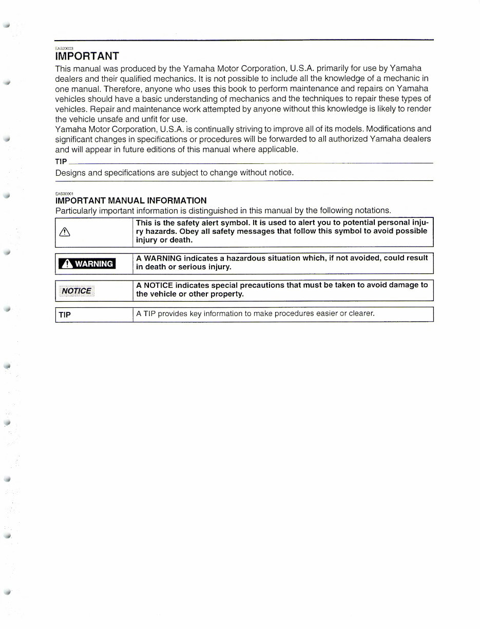
A WARNING
This is the safety alert symbol. It is used to alert you to potential personal inju-
ry hazards. Obey all safety messages that follow this symbol to avoid possible
injury or death.
A WARNING indicates a hazardous situation which, if not avoided, could result
in death or serious injury.
A NOTICE indicates special precautions that must be taken to avoid damage to
the vehicle or other property.
A TIP provides key information to make procedures easier or clearer.
EAS20004
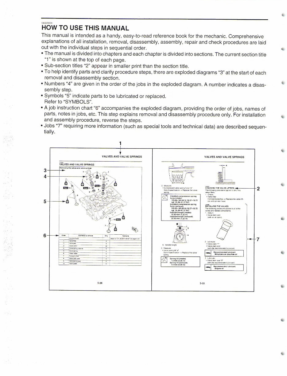
HOW TO USE THIS MANUAL
This manual is intended as a handy, easy-to-read reference book for the mechanic. Comprehensive
explanations of all installation, removal, disassembly, assembly, repair and check procedures are laid
out with the individual steps in sequential order.
•The manual is divided into chapters and each chapter is divided into sections. The current section title
"1" is shown at the top of each page.
• Sub-section titles "2" appear in smaller print than the section title.
•To help identify parts and clarify procedure steps, there are exploded diagrams "3" at the start of each
removal and disassembly section.
• Numbers "4" are given in the order of the jobs in the exploded diagram. A number indicates a disas-
sembly step.
• Symbols "5" indicate parts to be lubricated or replaced.
Refer to "SYMBOLS".
• A job instruction chart "6'' accompanies the exploded diagram, providing the order of jobs, names of
parts, notes in jobs, etc. This step explains removal and disassembly procedure only. For installation
and assembly procedure, reverse the steps.
• Jobs "7" requiring more information (such as special tools and technical data) are described sequen-
tially.
1
VALVES AND VALVE SPRINGS
VALVES AND VALVE SPRINGS
Removi ng the valves and valve springs
3-+------
4-+-- +---- --
5-+---+-t~
6
Cyhnderhtlad
Reier to "CVUNOER HEAD. 0t1 oaoe S.22
Valvo pad
I a
I '
Vatve9J)11n9 5eat
10 vatve g~
5-28
2. Measure:
• Compressed valve spring force "a~
Out of specification - Replace the valve
spring.
Installed compression spring
force (i ntake)
159.6<>-183.60 N (16.27- 18.72
kgl, 35.88-41 .27 lbl)
Installed compression spring
force (exhausl)
159.6<>-183.60 N (16.27- 18.72
kgl, 35.88-41 .27 lbl)
Installed lenglh (Intake)
30.90 mm (1.22 in)
Installed length (exhaust)
30.90 mm (1.22 in)
b. lnslalled length
3. Measure:
• Valve spring lilt ~a·
Out of specilication --+ Replace the valve
spnng
Spring tilt (I ntake)
1.6 mm (0.06 in)
Spring tilt (exhaust)
1.6 mm (0.06 In)
VALVES AND VALVE SPRINGS
5-33
~1~1~~~9~~~:~,~~:;;,~;~sa .... 11 ol l- the ----t-2
valve litters
1. Check:
•Valve titter
Damage/scratches --+ Replace the valve lift-
ers and cylinder head
mrALLING THE VALVES
The following procedure applies to all of the
'Valves and related componen1s.
1. Deburr:
• Valvestem end
(wilh an oil stone)
2. Lubricate·
• Valve stem ~,-
• Valve stem end
(wi th the recommended lubricant)
~ Recommended lubricant
Molybdenum dlsu111de oil
3. lubricate
• Valvestem seal"2-
(with the recommended lubricant)
..._. Recommended lubricant
Engine oU
7
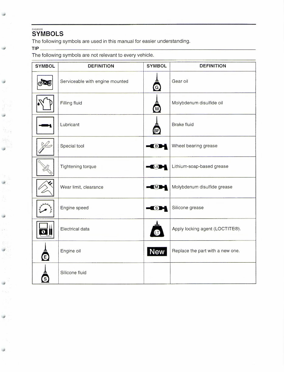
EAS20005
SYMBOLS
The following symbols are used in this manual for easier understanding.
TIP~~~~~~~~~~~~~~~~~~~~~~~~~~~~~~~~~~~~
The following symbols are not relevant to every vehicle.
SYMBOL DEFINITION SYMBOL
DEFINITION
~
Serviceable with engine mounted
1
Gear oil
~
~
Filling fluid
1
Molybdenum disulfide oil
~
B
Lubricant
1
Brake fluid
~
~
Special tool
~
Wheel bearing grease
1 ~~ 1
Tightening torque
~
Lithium-soap-based grease
~
Wear limit, clearance
-cM»t
Molybdenum disulfide grease
[g
Engine speed
-c§»I
Silicone grease
[i]jJ
'
Electrical data
tLTi
Apply locking agent (LOCTITE®).
1
l~ml
m
Engine oil
Replace the part with a new one.
1
Silicone fluid
m
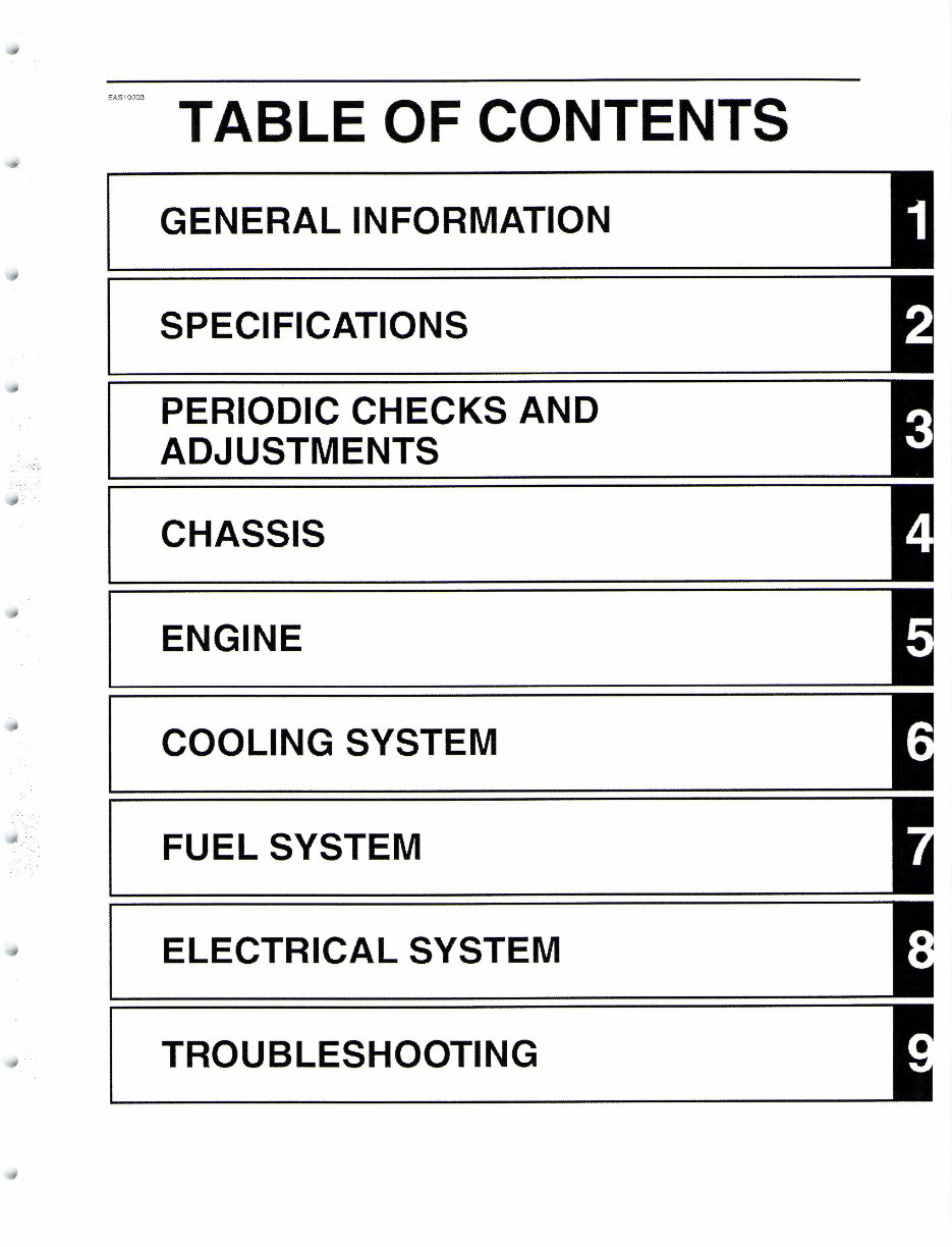
,,,,_ TABLE OF CONTENTS
GENERAL INFORMATION
SPECIFICATIONS
PERIODIC CHECKS AND
ADJUSTMENTS
CHASSIS
ENGINE
COOLING SYSTEM
FUEL SYSTEM
ELECTRICAL SYSTEM
TROUBLESHOOTING
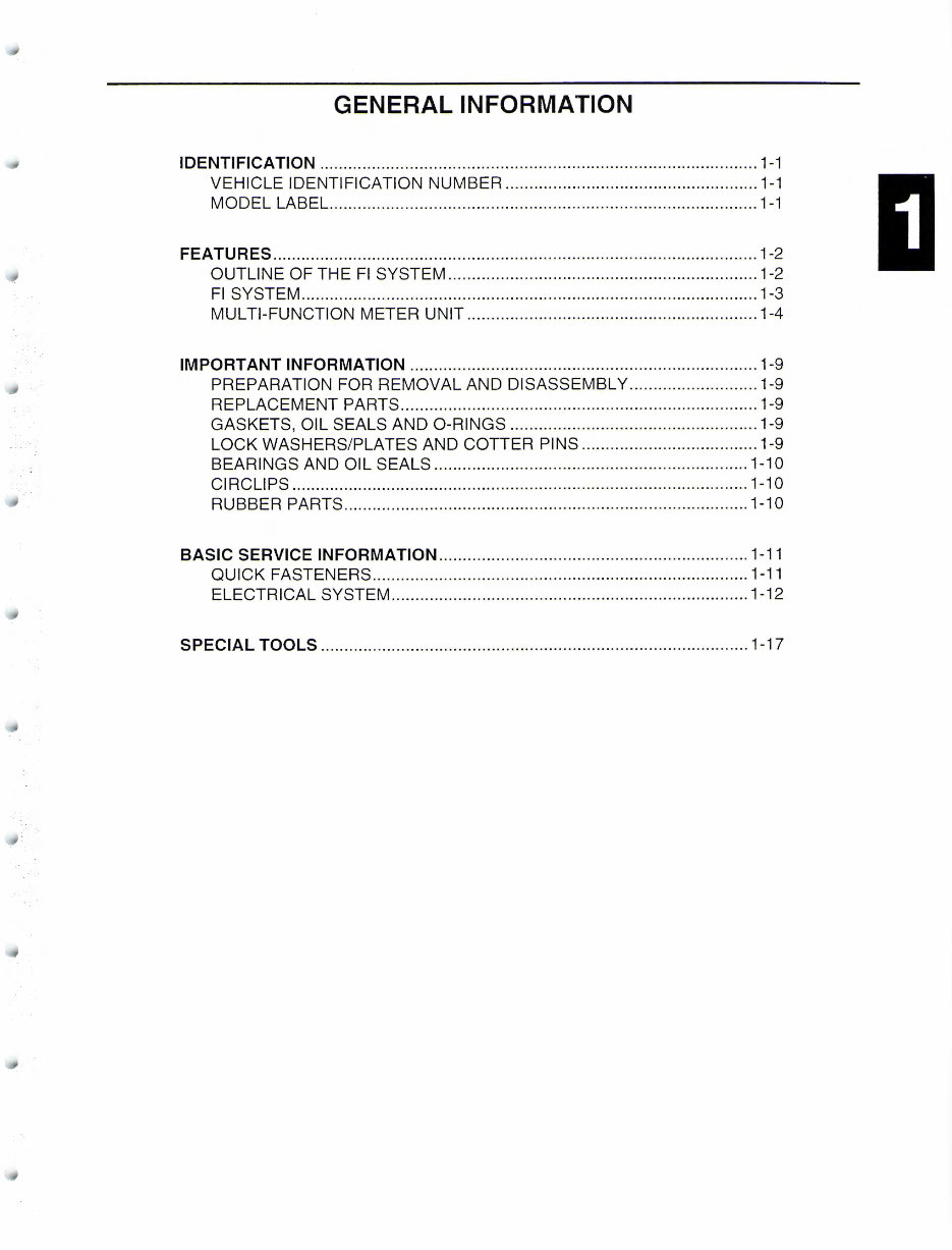
GENERAL INFORMATION
IDENTIFICATION ............................................................................................ 1-1
VEHICLE IDENTIFICATION NUMBER ..................................................... 1-1
MODEL LABEL .......................................................................................... 1-1
FEATURES ...................................................................................................... 1-2
OUTLINE OF THE Fl SYSTEM ................................................................. 1-2
Fl SYSTEM ................................................................................................ 1-3
MUL Tl-FUNCTION METER UNIT ............................................................. 1-4
IMPORTANT INFORMATION ......................................................................... 1-9
PREPARATION FOR REMOVAL AND DISASSEMBLY ........................... 1-9
REPLACEMENT PARTS ........................................................................... 1-9
GASKETS, OIL SEALS AND 0-RINGS .................................................... 1-9
LOCK WASHERS/PLATES AND COTTER PINS ..................................... 1-9
BEARINGS AND OIL SEALS .................................................................. 1-10
CIRCLIPS ................................................................................................ 1-10
RUBBER PARTS ..................................................................................... 1-10
BASIC SERVICE INFORMATION ................................................................. 1-11
QUICK FASTENERS ............................................................................... 1-11
ELECTRICAL SYSTEM ........................................................................... 1-12
SPECIAL TOOLS .......................................................................................... 1-17
EAS20007
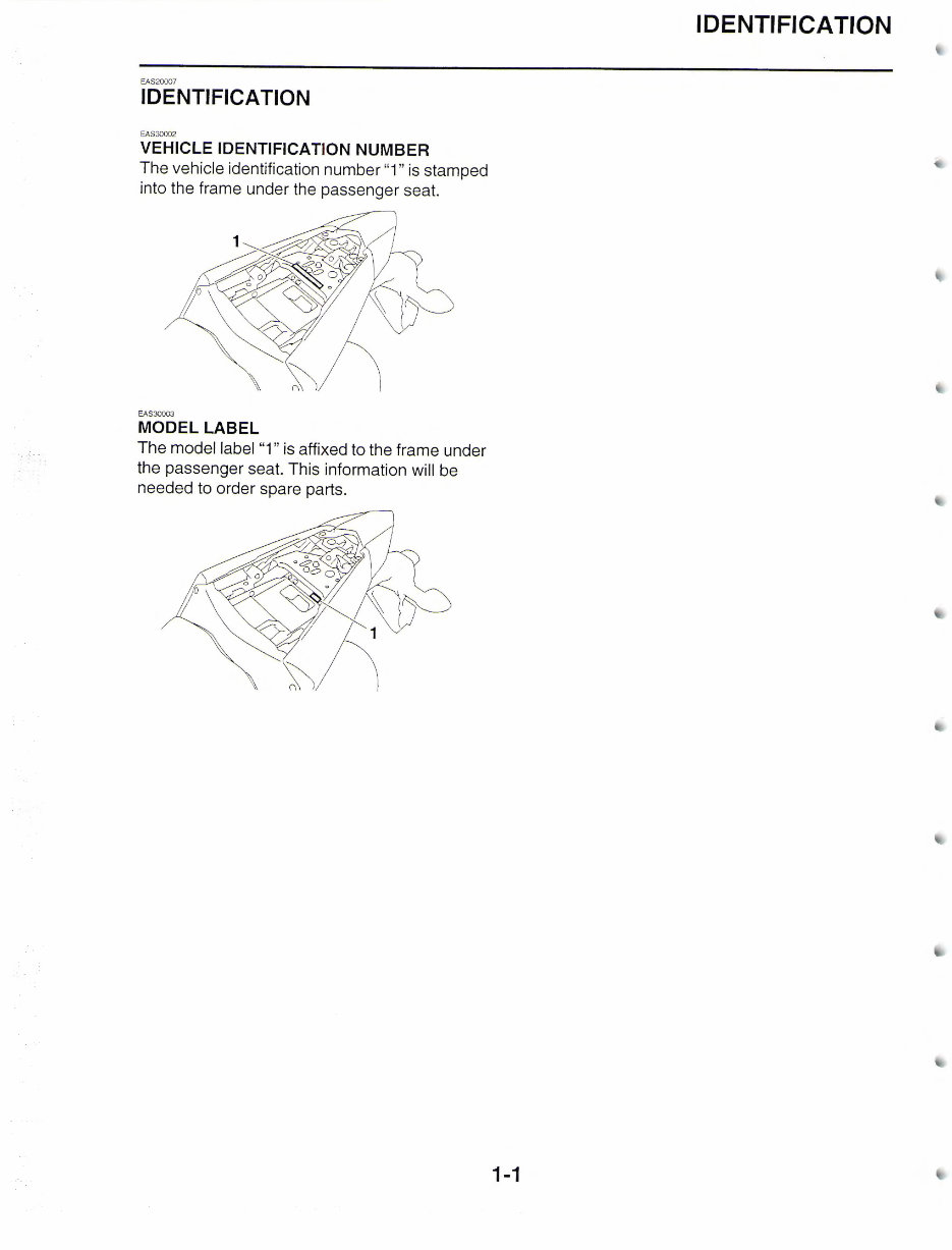
IDENTIFICATION
EAS30002
VEHICLE IDENTIFICATION NUMBER
The vehicle identification number "1" is stamped
into the frame under the passenger seat.
EAS30003
MODEL LABEL
The model label "1" is affixed to the frame under
the passenger seat. This information will be
needed to order spare parts.
IDENTIFICATION
1-1
FEATURES
EAS20008
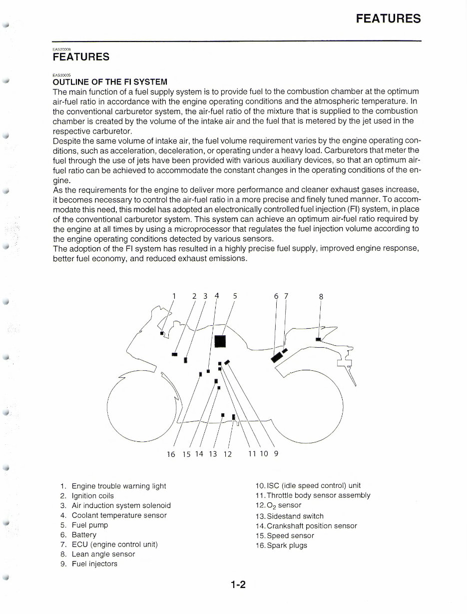
FEATURES
EAS30005
OUTLINE OF THE Fl SYSTEM
The main function of a fuel supply system is to provide fuel to the combustion chamber at the optimum
air-fuel ratio in accordance with the engine operating conditions and the atmospheric temperature. In
the conventional carburetor system, the air-fuel ratio of the mixture that is supplied to the combustion
chamber is created by the volume of the intake air and the fuel that is metered by the jet used in the
respective carburetor.
Despite the same volume of intake air, the fuel volume requirement varies by the engine operating con-
ditions, such as acceleration, deceleration, or operating under a heavy load. Carburetors that meter the
fuel through the use of jets have been provided with various auxiliary devices, so that an optimum air-
fuel ratio can be achieved to accommodate the constant changes in the operating conditions of the en-
gine.
As the requirements for the engine to deliver more performance and cleaner exhaust gases increase,
it becomes necessary to control the air-fuel ratio in a more precise and finely tuned manner. To accom-
modate this need, this model has adopted an electronically controlled fuel injection (Fl) system, in place
of the conventional carburetor system. This system can achieve an optimum air-fuel ratio required by
the engine at all times by using a microprocessor that regulates the fuel injection volume according to
the engine operating conditions detected by various sensors.
The adoption of the Fl system has resulted in a highly precise fuel supply, improved engine response,
better fuel economy, and reduced exhaust emissions.
16 15 14 13 12
11 10 9
1. Engine trouble warning light 1 O. ISC (idle speed control) unit
2. Ignition coils
11. Throttle body sensor assembly
3. Air induction system solenoid
12. 0
2
sensor
4. Coolant temperature sensor
13. Sidestand switch
5. Fuel pump
14. Crankshaft position sensor
6. Battery
15. Speed sensor
7. ECU (engine control unit)
16. Spark plugs
8. Lean angle sensor
9. Fuel injectors
1-2
You're Reading a Preview
What's Included?
Fast Download Speeds
Online & Offline Access
Access PDF Contents & Bookmarks
Full Search Facility
Print one or all pages of your manual
$37.99
Viewed 87 Times Today


Secure transaction
What's Included?
Fast Download Speeds
Online & Offline Access
Access PDF Contents & Bookmarks
Full Search Facility
Print one or all pages of your manual
$37.99
2017 Yamaha YZF-R3 Service & Repair Manual
The comprehensive repair manual for the 2017 Yamaha YZF-R3 is designed to provide both professional mechanics and DIY enthusiasts with the technical information needed to maintain, troubleshoot, and repair their motorcycle.
- This manual covers a wide range of topics, including diagnosis, disassembly, and reassembly procedures for various components and systems.
- It also includes detailed specifications, diagrams, and step-by-step instructions for tasks such as routine maintenance, repairs, and overhauls.
- Suitable for both amateur and professional mechanics, this manual provides a valuable resource for anyone seeking to work on their Yamaha YZF-R3.
This manual is essential for anyone looking to perform complex procedures or maintain the overall health of their motorcycle. Whether you're a seasoned mechanic or just starting out, this comprehensive guide will help you keep your 2017 Yamaha YZF-R3 running smoothly and efficiently.


