EB001000 NOTICE This manual was produced by the Yamaha Motor Company, Ltd. primarily for use by Yamaha dealers and their qualified mechanics. It is not possible to include all the knowledge of a mechanic in one manual. Therefore, anyone who uses this book to perform maintenance and repairs on Yamaha vehicles should have a basic understanding of mechanics and the tech- niques to repair these types of vehicles. Repair and maintenance work attempted by anyone without this knowledge is likely to render the vehicle unsafe and unfit for use. Yamaha Motor Company, Ltd. is continually striving to improve all of its models. Modifica- tions and significant changes in specifications or procedures will be forwarded to all autho- rized Yamaha dealers and will appear in future editions of this manual where applicable. NOTE: Designs and specifications are subject to change without notice. EB002000 IMPORTANT MANUAL INFORMATION Particularly important information is distinguished in this manual by the following. The Safety Alert Symbol means ATTENTION! BECOME ALERT! YOUR SAFETY IS INVOLVED! Failure to follow WARNING instructions could result in severe injury or death to the motorcycle operator, a bystander or a person checking or repairing the motorcycle. A CAUTION indicates special precautions that must be taken to avoid damage to the motorcycle. A NOTE provides key information to make procedures easier or clearer. WARNING CAUTION: NOTE:
EB003000 HOW TO USE THIS MANUAL This manual is intended as a handy, easy-to-read reference book for the mechanic. Compre- hensive explanations of all installation, removal, disassembly, assembly, repair and check procedures are laid out with the individual steps in sequential order. 1 The manual is divided into chapters. An abbreviation and symbol in the upper right corner of each page indicate the current chapter. Refer to “SYMBOLS”. 2 Each chapter is divided into sections. The current section title is shown at the top of each page, except in Chapter 3 (“PERIODIC CHECKS AND ADJUSTMENTS”), where the sub-sec- tion title(-s) appears. 3 Sub-section titles appear in smaller print than the section title. 4 To help identify parts and clarify procedure steps, there are exploded diagrams at the start of each removal and disassembly section. 5 Numbers are given in the order of the jobs in the exploded diagram. A circled number indi- cates a disassembly step. 6 Symbols indicate parts to be lubricated or replaced. Refer to “SYMBOLS”. 7 A job instruction chart accompanies the exploded diagram, providing the order of jobs, names of parts, notes in jobs, etc. 8 Jobs requiring more information (such as special tools and technical data) are described sequentially.
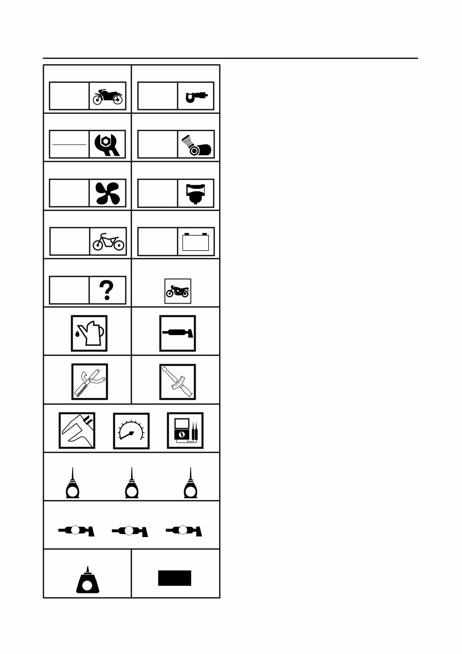
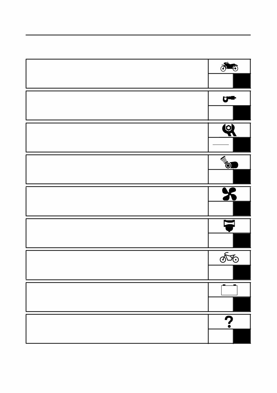
EB004000 SYMBOLS The following symbols are not relevant to every vehicle. Symbols 1 to 9 indicate the subject of each chapter. 1 General information 2 Specifications 3 Periodic checks and adjustments 4 Engine 5 Cooling system 6 Carburetor(-s) 7 Chassis 8 Electrical system 9 Troubleshooting Symbols 0 to G indicate the following. 0 Serviceable with engine mounted A Filling fluid B Lubricant C Special tool D Tightening torque E Wear limit, clearance F Engine speed G Electrical data Symbols H to M in the exploded diagrams indicate the types of lubricants and lubrica- tion points. H Engine oil I Gear oil J Molybdenum disulfide oil K Wheel bearing grease L Lithium soap base grease M Molybdenum disulfide grease Symbols N to O in the exploded diagrams indicate the following. N Apply locking agent (LOCTITE ) O Replace the part 1 2 3 4 5 6 7 8 9 0 A B C D E F G H I J K L M N O GEN INFO SPEC CHK ADJ ENG COOL CARB CHAS – + ELEC TRBL SHTG T R . . G M E B LS M LT New
CHAPTER TITLES GENERAL INFORMATION 1 SPECIFICATIONS SPEC 2 PERIODIC CHECKS AND ADJUSTMENTS 3 ENGINE ENG 4 COOLING COOL 5 CARBURETION CARB 6 CHASSIS CHAS 7 ELECTRICAL ELEC 8 TROUBLESHOOTING 9 GEN INFO CHK ADJ – + TRBL SHTG
GEN INFO 1
GEN INFO CHAPTER 1. GENERAL INFORMATION MOTORCYCLE IDENTIFICATION ................................................................. 1-1 VEHICLE IDENTIFICATION NUMBER .................................................. 1-1 MODEL CODE ....................................................................................... 1-1 IMPORTANT INFORMATION ....................................................................... 1-2 PREPARATION FOR REMOVAL AND DISASSEMBLY ....................... 1-2 REPLACEMENT PARTS ........................................................................ 1-2 GASKETS, OIL SEALS AND O-RINGS ................................................ 1-2 USING A DYNAMOMETER .................................................................. 1-3 LOCK WASHERS/PLATES AND COTTER PINS .................................. 1-3 BEARINGS AND OIL SEALS ................................................................ 1-3 CIRCLIPS ............................................................................................... 1-3 CHECKING THE CONNECTIONS ................................................................. 1-4 SPECIAL TOOLS ........................................................................................... 1-5
GEN INFO
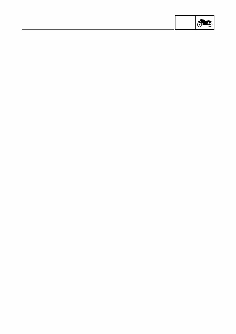
1 - 1 GEN INFO MOTORCYCLE IDENTIFICATION EB100000 GENERAL INFORMATION MOTORCYCLE IDENTIFICATION EB100010 VEHICLE IDENTIFICATION NUMBER The vehicle identification number 1 is stamped into the right side of the steering head pipe. EB100020 MODEL CODE The model code label 1 is affixed to the frame. This information will be needed to order spare parts.
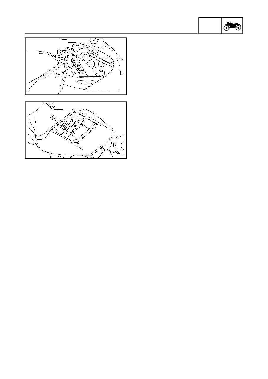
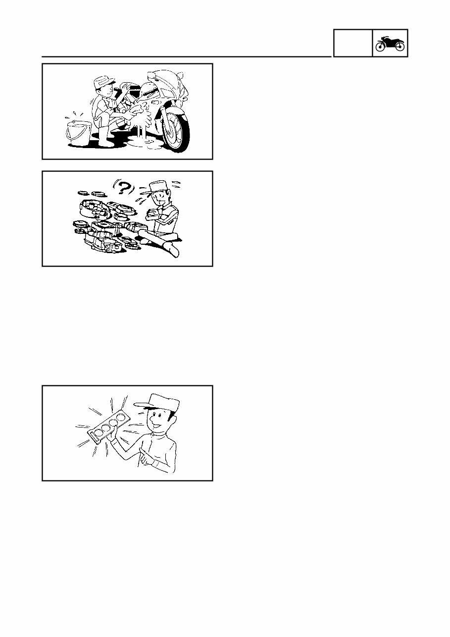
1 - 2 GEN INFO IMPORTANT INFORMATION EB102000 IMPORTANT INFORMATION PREPARATION FOR REMOVAL AND DISASSEMBLY 1. Before removal and disassembly, remove all dirt, mud, dust, and foreign material. 2. Use only the proper tools and cleaning equipment. Refer to “SPECIAL TOOLS”. 3. When disassembling, always keep mated parts together. This includes gears, cylinders, pistons and other parts that have been “mated” through normal wear. Mated parts must always be reused or replaced as an assembly. 4. During disassembly, clean all of the parts and place them in trays in the order of disassembly. This will speed up assembly and allow for the correct installation of all parts. 5. Keep all parts away from any source of fire. EB102010 REPLACEMENT PARTS Use only genuine Yamaha parts for all replacements. Use oil and grease recom- mended by Yamaha for all lubrication jobs. Other brands may be similar in function and appearance, but inferior in quality. EB102020 GASKETS, OIL SEALS AND O-RINGS 1. When overhauling the engine, replace all gaskets, seals, and O-rings. All gasket surfaces, oil seal lips, and O-rings must be cleaned. 2. During reassembly, properly oil all mat- ing parts and bearings and lubricate the oil seal lips with grease.
This Service Repair Workshop Manual provides a comprehensive and easily navigable layout, offering detailed repair procedures. It is designed to enhance your understanding of your vehicle's components and repair processes, making it suitable for both professional mechanics and DIY enthusiasts.
All models for the specified years and engine types are covered in this manual, ensuring specificity and relevance to your vehicle. It is akin to the type of manual utilized by local dealers and mechanics.
The manual encompasses a wide range of information, including routine maintenance, tune-up procedures, engine specifications, installation and removal, lubrication, exhaust systems, heating, emissions, transmission, steering, suspension, brakes (including ABS), body, air conditioning, electrical systems, safety restraints, and more.
Upon payment via Credit/Debit/Paypal Account, the manual is instantly accessible without the need for shipping, enabling immediate utilization for your repair needs.
By utilizing this manual, significant cost savings can be achieved, empowering you to undertake various repairs independently, thereby avoiding excessive charges from mechanics.
Utilizing this manual is straightforward and user-friendly, compatible with PC/MAC computers using Microsoft Windows, including XP, NT, 2000, Vista, and Windows 7.