EAS20003 IMPORTANT This manual was produced by the Yamaha Motor Company, Ltd. primarily for use by Yamaha dealers and their qualified mechanics. It is not possible to include all the knowledge of a mechanic in one man- ual. Therefore, anyone who uses this book to perform maintenance and repairs on Yamaha vehicles should have a basic understanding of mechanics and the techniques to repair these types of vehicles. Repair and maintenance work attempted by anyone without this knowledge is likely to render the vehi- cle unsafe and unfit for use. Yamaha Motor Company, Ltd. is continually striving to improve all of its models. Modifications and sig- nificant changes in specifications or procedures will be forwarded to all authorized Yamaha dealers and will appear in future editions of this manual where applicable. TIP Designs and specifications are subject to change without notice. EAS30001 IMPORTANT MANUAL INFORMATION Particularly important information is distinguished in this manual by the following notations. This is the safety alert symbol. It is used to alert you to potential per- sonal injury hazards. Obey all safety messages that follow this symbol to avoid possible injury or death. A WARNING indicates a hazardous situation which, if not avoided, could result in death or serious injury. A NOTICE indicates special precautions that must be taken to avoid damage to the vehicle or other property. A TIP provides key information to make procedures easier or clearer. WARNING NOTICE TIP
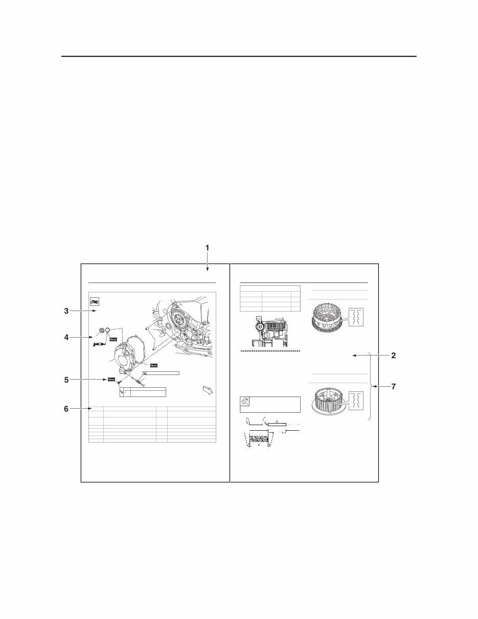
EAS20004 HOW TO USE THIS MANUAL This manual is intended as a handy, easy-to-read reference book for the mechanic. Comprehensive explanations of all installation, removal, disassembly, assembly, repair and check procedures are laid out with the individual steps in sequential order. • The manual is divided into chapters and each chapter is divided into sections. The current section title “1” is shown at the top of each page. • Sub-section titles “2” appear in smaller print than the section title. • To help identify parts and clarify procedure steps, there are exploded diagrams “3” at the start of each removal and disassembly section. • Numbers “4” are given in the order of the jobs in the exploded diagram. A number indicates a disas- sembly step. • Symbols “5” indicate parts to be lubricated or replaced. Refer to “SYMBOLS”. • A job instruction chart “6” accompanies the exploded diagram, providing the order of jobs, names of parts, notes in jobs, etc. This step explains removal and disassembly procedure only. For installation and assembly procedure, reverse the steps. • Jobs “7” requiring more information (such as special tools and technical data) are described sequen- tially. CLUTCH 5-53 EAS20055 CLUTCH Removing the clutch cover * Following the tightening order, loosen the bolt one byone, and then retighten it to the specific torque. Order Job/Parts to remove Q’ty Remarks Front side cowling (right) Refer to “GENERAL CHASSIS (2)” on page 4-7. Engine oil Drain. Refer to “CHANGING THE ENGINE OIL” on page 3-30. . t c e n n o c s i D 1 e l b a c h c t u l C 1 1 r e v o c h c t u l C 2 1 t e k s a g r e v o c h c t u l C 3 2 n i p l e w o D 4 1 p a c r e l l i f l i O 5 FWD FWD 1 2 3 4 5 (10) 6 Nm (0.6 m • kgf, 4.3 ft • Ibf) 3.0 Nm (0.30 m • kgf, 2.2 ft • Ibf) 1st 2nd Specified angle 90° 7 Nm (0.7 m • kgf, 5.1 ft • lbf) CLUTCH 5-58 EAS30351 CHECKING THE CLUTCH SPRINGS The following procedure applies to all of the clutch springs. 1. Check: • Clutch spring Damage → Replace the clutch springs as a set. 2. Measure: • Clutch spring free length “a” Out of specification → Replace the clutch springs as a set. EAS30352 CHECKING THE CLUTCH HOUSING 1. Check: • Clutch housing dogs Damage/pitting/wear → Deburr the clutch housing dogs or replace the clutch housing. TIP Pitting on the clutch housing dogs will cause er- ratic clutch operation. 2. Check: • Bearing Damage/wear → Replace the bearing and clutch housing. EAS30353 CHECKING THE CLUTCH BOSS 1. Check: • Clutch boss splines Damage/pitting/wear → Replace the clutch boss. TIP Pitting on the clutch boss splines will cause er- ratic clutch operation. EAS30354 CHECKING THE PRESSURE PLATE 1. Check: • Pressure plate 1 “1” • Pressure plate 2 “2” Cracks/damage →Replace. • Bearing “3” Damage/wear →Replace. Clutch plate “1” Part No. Thickness 2CR-16325-10 2.0 mm (0.079 in) 2CR-16325-00 2.3 mm (0.091 in) STD 2CR-16325-20 2.6 mm (0.102 in) Clutch spring free length 47.36 mm (1.86 in) Limit 44.99 mm (1.77 in) 1
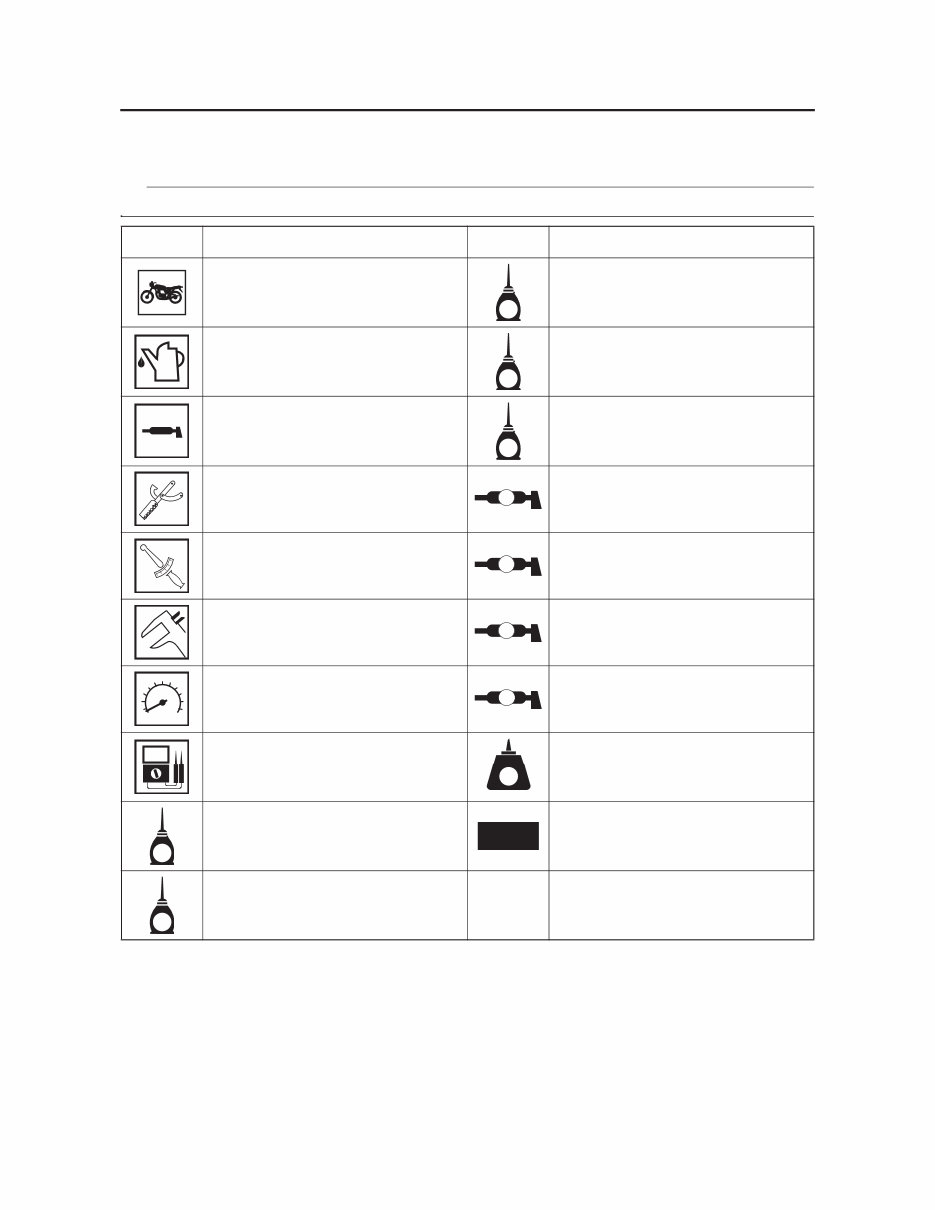
EAS20005 SYMBOLS The following symbols are used in this manual for easier understanding. TIP The following symbols are not relevant to every vehicle. SYMBOL DEFINITION SYMBOL DEFINITION Serviceable with engine mounted Gear oil Filling fluid Molybdenum disulfide oil Lubricant Brake fluid Special tool Wheel bearing grease Tightening torque Lithium-soap-based grease Wear limit, clearance Molybdenum disulfide grease Engine speed Silicone grease Electrical data Apply locking agent (LOCTITE®). Engine oil Replace the part with a new one. Silicone fluid G M BF B T R . . LS M S LT E New S
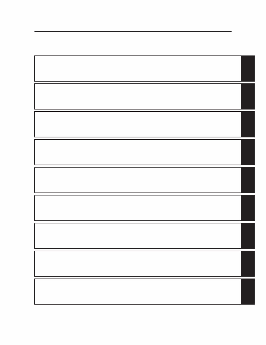
GENERAL INFORMATION 1 SPECIFICATIONS 2 PERIODIC CHECKS AND ADJUSTMENTS 3 CHASSIS 4 ENGINE 5 COOLING SYSTEM 6 FUEL SYSTEM 7 ELECTRICAL SYSTEM 8 TROUBLESHOOTING 9 EAS10003 TABLE OF CONTENTS
1 2 3 4 5 6 7 8 9 GENERAL INFORMATION IDENTIFICATION.............................................................................................. 1-1 VEHICLE IDENTIFICATION NUMBER ...................................................... 1-1 MODEL LABEL........................................................................................... 1-1 FEATURES ....................................................................................................... 1-2 OUTLINE OF THE FI SYSTEM .................................................................. 1-2 FI SYSTEM................................................................................................. 1-3 YCC-T (Yamaha Chip Controlled Throttle)/YCC-I (Yamaha Chip Controlled Intake) .............................................................. 1-5 ELECTRONIC CONTROL-RELATED FEATURES .................................... 1-8 OUTLINE OF THE UBS ........................................................................... 1-13 OUTLINE OF THE ABS............................................................................ 1-17 ABS COMPONENT FUNCTIONS ............................................................ 1-22 UBS AND ABS OPERATION ................................................................... 1-26 ABS WARNING LIGHT AND OPERATION.............................................. 1-30 ABS AND UBS FUNCTION ...................................................................... 1-31 GLOSSARY .............................................................................................. 1-32 DISPLAY .................................................................................................. 1-32 MENU SCREEN ....................................................................................... 1-36 IMPORTANT INFORMATION ......................................................................... 1-48 PREPARATION FOR REMOVAL AND DISASSEMBLY.......................... 1-48 REPLACEMENT PARTS.......................................................................... 1-48 GASKETS, OIL SEALS AND O-RINGS ................................................... 1-48 ALUMINUM BOLTS.................................................................................. 1-48 LOCK WASHERS/PLATES AND COTTER PINS .................................... 1-49 BEARINGS AND OIL SEALS ................................................................... 1-49 CIRCLIPS ................................................................................................. 1-49 RUBBER PARTS...................................................................................... 1-49 BASIC SERVICE INFORMATION .................................................................. 1-50 QUICK FASTENERS................................................................................ 1-50 ELECTRICAL SYSTEM............................................................................ 1-51 SPECIAL TOOLS ........................................................................................... 1-56
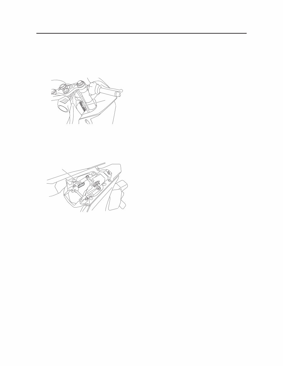
IDENTIFICATION 1-1 EAS20007 IDENTIFICATION EAS30002 VEHICLE IDENTIFICATION NUMBER The vehicle identification number “1” is stamped into the right side of the steering head pipe. EAS30003 MODEL LABEL The model label “1” is affixed to the frame under the passenger seat. This information will be needed to order spare parts. 1 1
Enhance the performance of your 2015-2017 Yamaha YZF-R1 with this detailed Service & Repair Manual. This guide provides extensive instructions for maintenance, troubleshooting, and repairs, making it perfect for motorcycle enthusiasts and professional mechanics. It includes step-by-step procedures, clear illustrations, and comprehensive exploded-view diagrams.
The Yamaha YZF-R1 is known for its cutting-edge technology and superbike performance, demanding skilled maintenance and precise repairs to maintain its elite status. This manual offers expert knowledge and procedures recommended by Yamaha, covering a wide range of service and repair topics.
From engine servicing and tuning to chassis adjustments and electrical system diagnostics, this manual covers a broad spectrum of topics. Its instructions are clear and easy to follow, supported by detailed visuals, making even complex repairs manageable for both seasoned mechanics and DIY riders.
This manual is available in a digital format, easily accessible on a variety of devices, including PCs, tablets, and smartphones. This format allows for efficient searching and navigation, enhancing your repair and maintenance experience over traditional paper manuals. It's an essential resource for keeping your 2015-2017 Yamaha YZF-R1 performing at its best, whether on the track or the road.
Printable: Yes
Language: English
Compatibility: Compatible across a wide range of devices including PCs, Macs, smartphones, and tablets.
Requirements: A PDF reader like Adobe Reader (free)