WARNING This Manual was written by Yamaha Motor España, S.A. principally for the use of Yamaha/MBK agents and qualified mechanics. As it is not possible to give full mechanical instructions in a manual, it is presumed that the persons using the book to carry out the maintenance and repair of Yamaha/MBK motorcycles have a basic knowledge of the concepts and procedures inherent in the technology of motorcycle repair. Without such knowledge any attempt to repair or service this model may cause problems in its use and/or safety. Yamaha Motor España, S.A., is continually trying to improve all models which it manufactures. Authorised Yamaha/MBK agents will be notified of all significant modifications and changes in the specifications or procedures and these will appear where applicable in future editions of this manual. PARTICULARLY IMPORTANT INFORMATION This material used the following notation. s A danger symbol means ATTENTION, BE CAREFUL, YOUR SAFETY IS IN DANGER! WARNING Non-compliance with a WANING may cause the serious injury or death of the driver, a bystander or the person inspecting of repairing the mortorcycle. ATTENTION: ATTENTION indicates the special precautions which should be taken in order to avoid damage to the motorcycle. NOTE: NOTE provides key information to make the procedures easier and clearer.
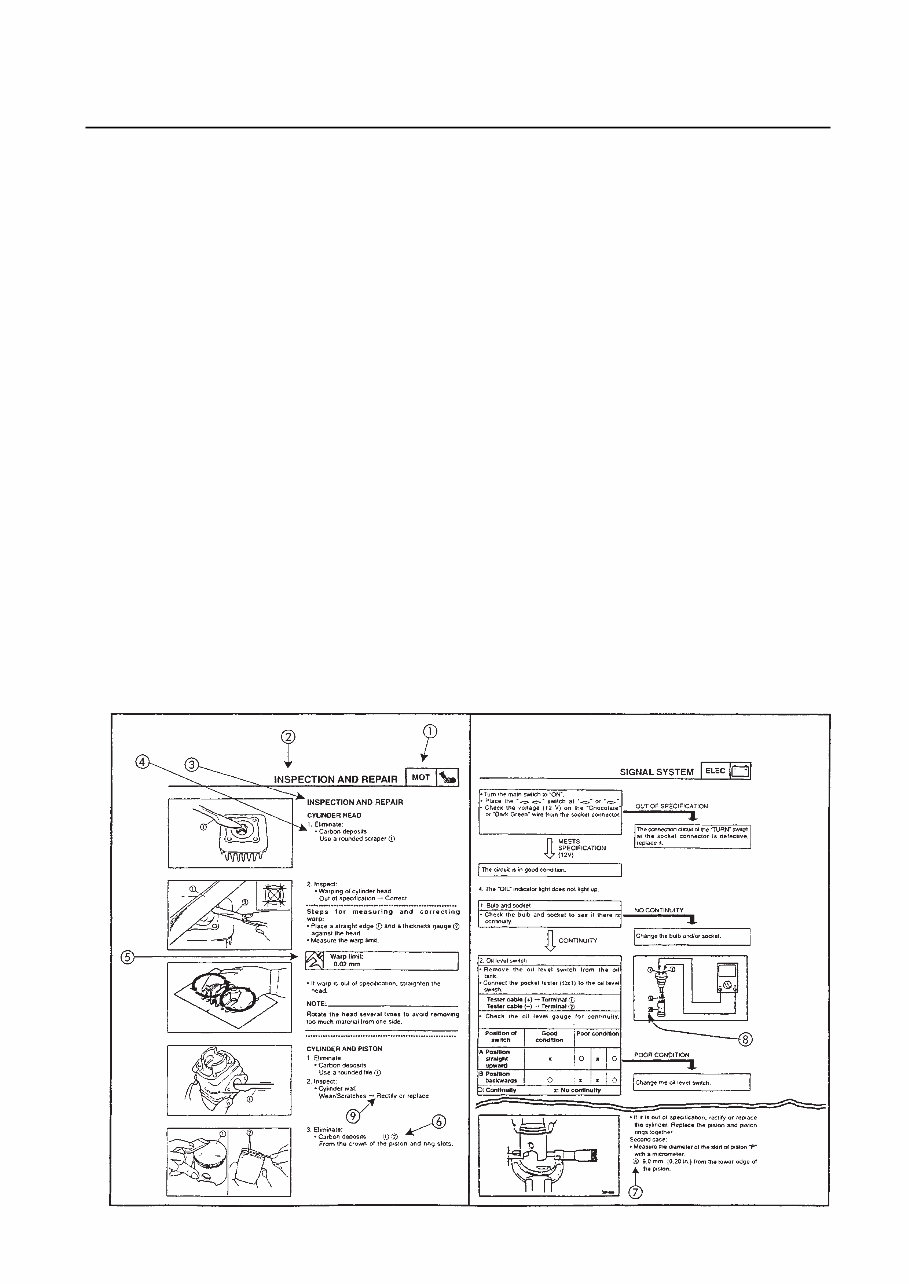
HOW TO USE THIS MANUAL FORMAT OF THIS MANUAL This manual is composed of chapters on the main subject categories (See “Illustrated Symbols”). First heading : This is a chapter with a symbol at the top right-hand side of each page. Second heading : This title appears at the top of each page to the left of the chapter symbol. (For the “Inspection and periodic adjustments” chapter the third heading appears) Third heading : This is a final heading. MANUAL FORMAT All procedures in this manual are organised sequentially, step by step. The information has been compiled to make reading easy for the mechanic and to provide useful reference material which contains ample explanations of all disassembly, repair, assembly and inspection procedures. A particularly important procedure is placed between a lines of asterisks “**” with each procedu- re preceded by “•”. IMPORTANT CHARACTERISTICS • Data and special tools are put in a box preceded by a corresponding symbol . • A number within a circle indicates the number of a part, and an alphabetical letter within a circle indicates data or an alignment mark , everything else is indicated by a letter within a box . • The conditions of defective components will precede an arrow symbol and the course of action to be followed will follow the symbol . DETAILED DIAGRAM Each chapter provides detailed diagrams before each disassembly section, for the easy identifica- tion of disassembly/assembly procedures.
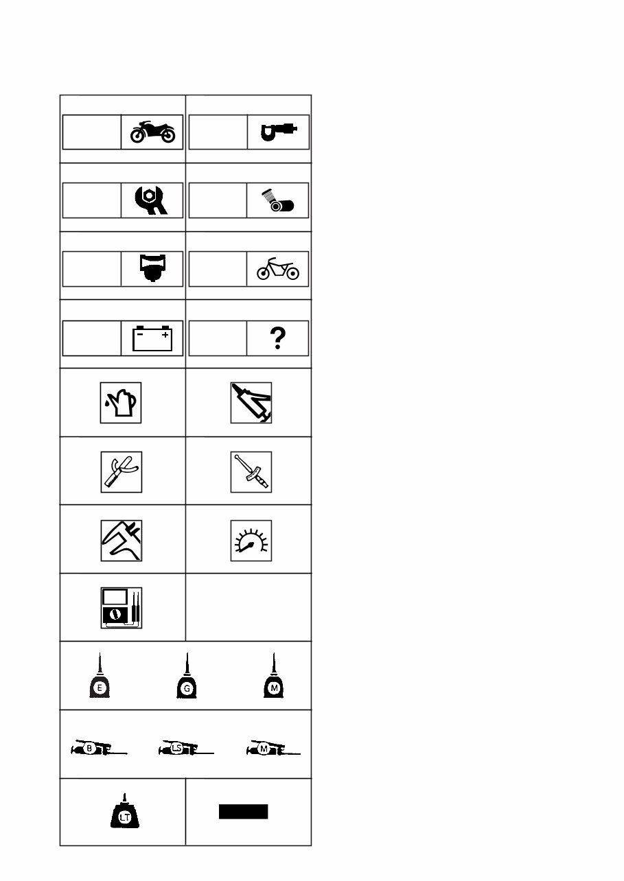
ILLUSTRATED SYMBOLS (See illustration) Illustrated symbols to are designed as tabs to be followed with the thumb to indicate the chapter number and the index. General information Specifications Periodic inspection and adjustment General overhaul of the engine Carburation Chassis Electrical system Troubleshooting Illustrated symbols to 15 will be used to identify the specifications which appear in the text. Refill with fluid 10 Lubricant 11 Special tool 12 Tightening 13 Wear limit, clearance 14 Engine speed 15 Ω V, A Illustrated symbols 16 to 23 of detailed dia- grams, indicate the degree of lubricant and the location of the lubrication point. 16 Apply engine oil 17 Apply gear oil 18 Apply molybdenum disulphide oil 19 Apply grease to wheel bearings 20 Apply grease with lightweight lithium soap base 21 Apply molybdenum disulphide grease 22 Apply bonding agent (LOCTITE®) 23 Use a new part. INSP/ ADJ CHAS TRBL/ SHTG SPEC ENG CARB GEN INFO NEW 11 13 15 16 19 22 10 12 14 23 18 21 17 20 ELEC
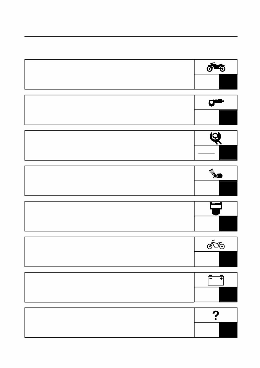
SPEC 2 SPECIFICATIONS INSP ADJ 3 PERIODIC INSPECTION AND ADJUSTMENTS ENG 4 GENERAL OVERHAUL OF ENGINE CARB 5 CARBURATION CHAS 6 CHASSIS ELEC 7 ELECTRICAL SYSTEM INDEX TRBL SHTG 8 TROUBLESHOOTING GENERAL INFORMATION GEN/ INFO 1
GEN/ INFO 1
GEN/ INFO CHAPTER 1 GENERAL INFORMATION IDENTIFICATION OF THE SCOOTER …………………………………………1-1 SERIAL NUMBER OF THE FRAME …………………………………………1-1 ENGINE SERIAL NUMBER……………………………………………………1-1 IMPORTANT INFORMATION …………………………………………………1-2 CHANGE OF ALL PARTS ……………………………………………………1-2 OIL SEALS AND O-RINGS ……………………………………………………1-2 SEALING WASHERS/PLATE AND KEYS……………………………………1-2 BEARING AND OIL SEALS …………………………………………………1-2 CIRCLIPS ………………………………………………………………………1-3 SPECIAL TOOLS …………………………………………………………………1-3 FOR SERVICING THE ENGINE ………………………………………………1-3 FOR SERVICING THE CHASSIS ……………………………………………1-5 FOR ELECTRICAL COMPONENTS …………………………………………1-6
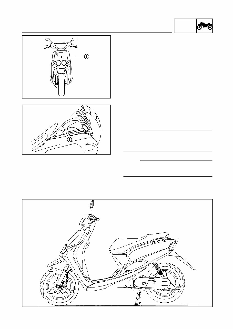
GEN/ INFO IDENTIFICATION OF THE SCOOTER 1-1 GENERAL INFORMATION SCOOTER IDENTIFICATION FRAME SERIAL NUMBER The serial number of the frame is stamped on the steering head pipe. Frame VTL5AD according standard EU0 Frame VTLSA15 according standard EU1 Frame VTLSA19 according Mofa Version ENGINE SERIAL NUMBER The engine serial number is stamped on the upper part of the rear left-hand section of the gear box. NOTE: The first three digits of these numbers identify the model, the remaining digits are the manu- facturing number of the unit. NOTE: The designs and specification are subject to change without prior notice.
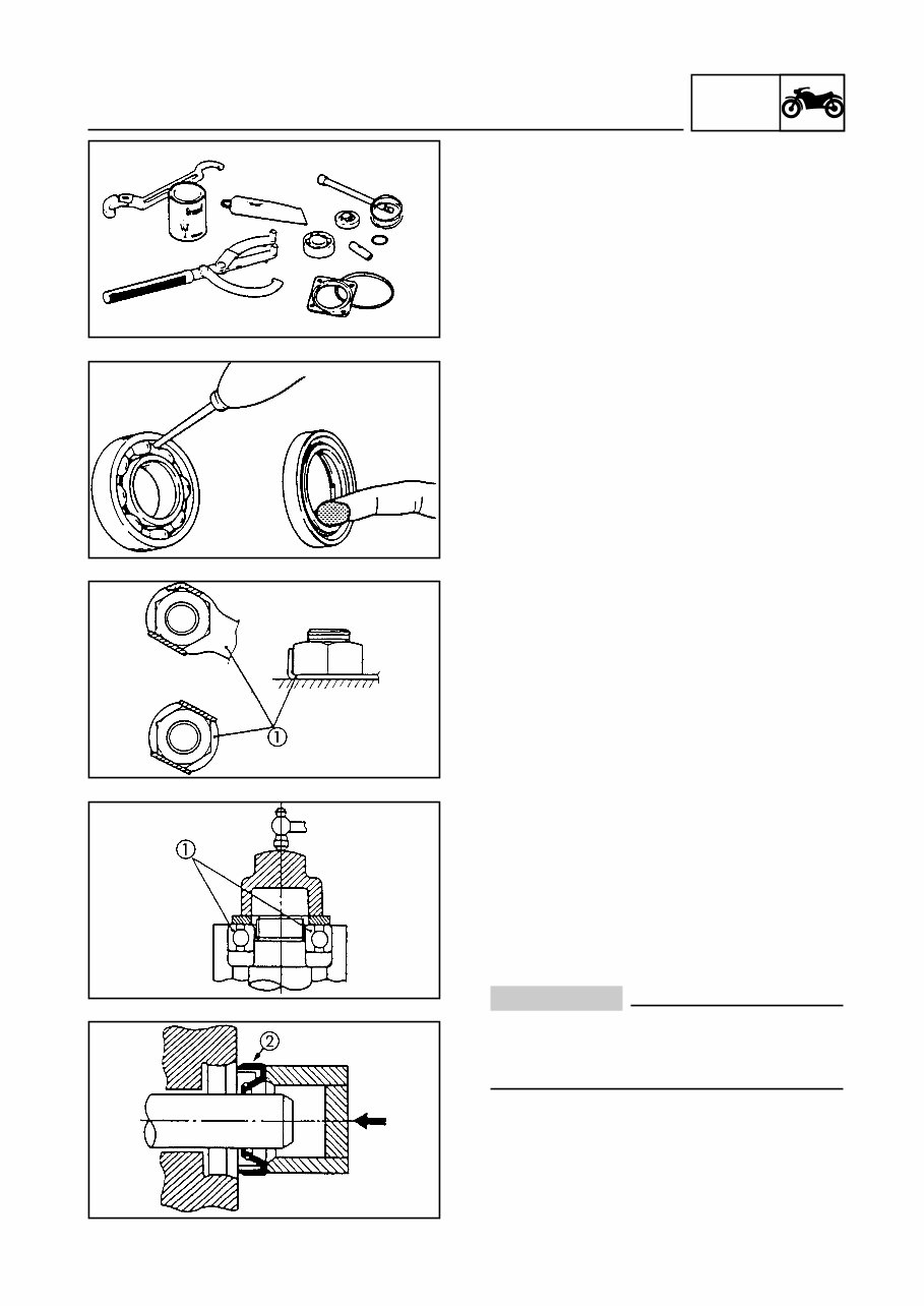
GEN/ INFO IMPORTANT INFORMATION 1-2 IMPORTANT INFORMATION CHANGE OF ALL PARTS 1. We recommend that original Yamaha parts are used as spare parts. Use the oil and/or grease recommended by Yamaha for assembly and adjustment. GASKETS, OIL SEALS AND O-RINGS 1. All gaskets and o-rings should be replaced when the engine is overhauled and repaired. All gasket surfaces, the lips of seals and o- rings should be cleaned. 2. Lubricate with grease all corresponding parts and bearings during assembly. Apply grease on the lips of seals. SEALING WASHER/PLATES AND KEYS 1. All washers/plates and keys should be replaced when they are removed. The loc- king tabs should be folded along the flat parts of the bolts or nuts after correctly tigh- tening them. BEARINGS AND OIL SEALS 1. Install the bearings and oil seals with their manufacturer’s marks or numbers facing outwards (i.e. the printed letters should on the side exposed to view). When the oil seals are installed, apply a thin layer of light lithium-based grease on the edges of the seal. Put oil on the bearings when they are installed. ATTENTION: Do not turn the bearings in compressed air to dry them. This will damage the surface of the bearings.
Get the job done today with this professional quality, highly detailed service repair workshop manual. Whether you're a professional mechanic or a DIY enthusiast, this manual provides step-by-step instructions, along with highly detailed exploded pictures and diagrams, to help you efficiently complete all repair procedures. It covers the entire vehicle from front to back, including the engine, gearbox & clutch, cooling system, fuel system, braking system, suspension, electrical system, body & fixtures, exhaust system, wheels & tyres, wiring diagrams, maintenance, technical information & specifications, and much more.
This manual is very easy to use and allows you to print what you need when you need it. It's the only service repair workshop manual you will ever need, and there are no shipping costs or waiting for a CD or paper manual to arrive in the mail. It's available for instant access on completion of payment via our secure payment processor, with compatibility for both PC and MAC. Click on the instant button above to get started today.
Engine
Gearbox & Clutch
Cooling System
Fuel System
Braking System
Suspension
Electrical System
Body & Fixtures
Exhaust System
Wheels & Tyres
Wiring Diagrams
Maintenance
Technical Information & Specifications
All rights reserved. Designated trademarks and brands are the property of their respective owners.