1998-2010 Yamaha XVZ13TFL(C), XVZ13CCT(C) Royal Star Venture/Midnight Venture/Tour Deluxe Motorcycle Workshop Repair Service Man
What's Included?
Lifetime Access
Fast Download Speeds
Online & Offline Access
Access PDF Contents & Bookmarks
Full Search Facility
Print one or all pages of your manual
NOTE: CAUTION: EAS00003 NOTICE This manual was produced by the Yamaha Motor Company, Ltd. primarily for use by Yamaha dealers and their qualified mechanics. It is not possible to include all the knowledge of a mechanic in one manu- al. Therefore, anyone who uses this book to perform maintenance and repairs on Yamaha vehicles should have a basic understanding of mechanics and the techniques to repair these types of vehicles. Repair and maintenance work attempted by anyone without this knowledge is likely to render the ve- hicle unsafe and unfit for use. This model has been designed and manufactured to perform within certain specifications in regard to performance and emissions. Proper service with the correct tools in necessary to ensure that the ve- hicle will operate as designed. If there is any question about a service procedure, it is imperative that you contact a Yamaha dealer for any service information changes that apply to this model. This policy is intended to provide the customer with the most satisfaction from his vehicle and to conform with fed- eral environmental quality objectives. Yamaha Motor Company, Ltd. is continually striving to improve all its models. Modifications and signifi- cant changes in specifications or procedures will be forwarded to all authorized Yamaha dealers and will appear in future editions of this manual where applicable. S This Service Manual contains information regarding periodic maintenance to the emission control system. Please read this material carefully. S Designs and specifications are subject to change without notice. EAS00004 IMPORTANT INFORMATION Particularly important information is distinguished in this manual by the following notations. The Safety Alert Symbol means ATTENTION! BECOME ALERT! YOUR SAFETY IS INVOLVED! Failure to follow WARNING instructions could result in severe injury or death to the motorcycle operator, a bystander or a person inspecting or repairing the motorcycle. A CAUTION indicates special precautions that must be taken to avoid damage to the motorcycle. NOTE: A NOTE provides key information to make procedures easier or clearer.
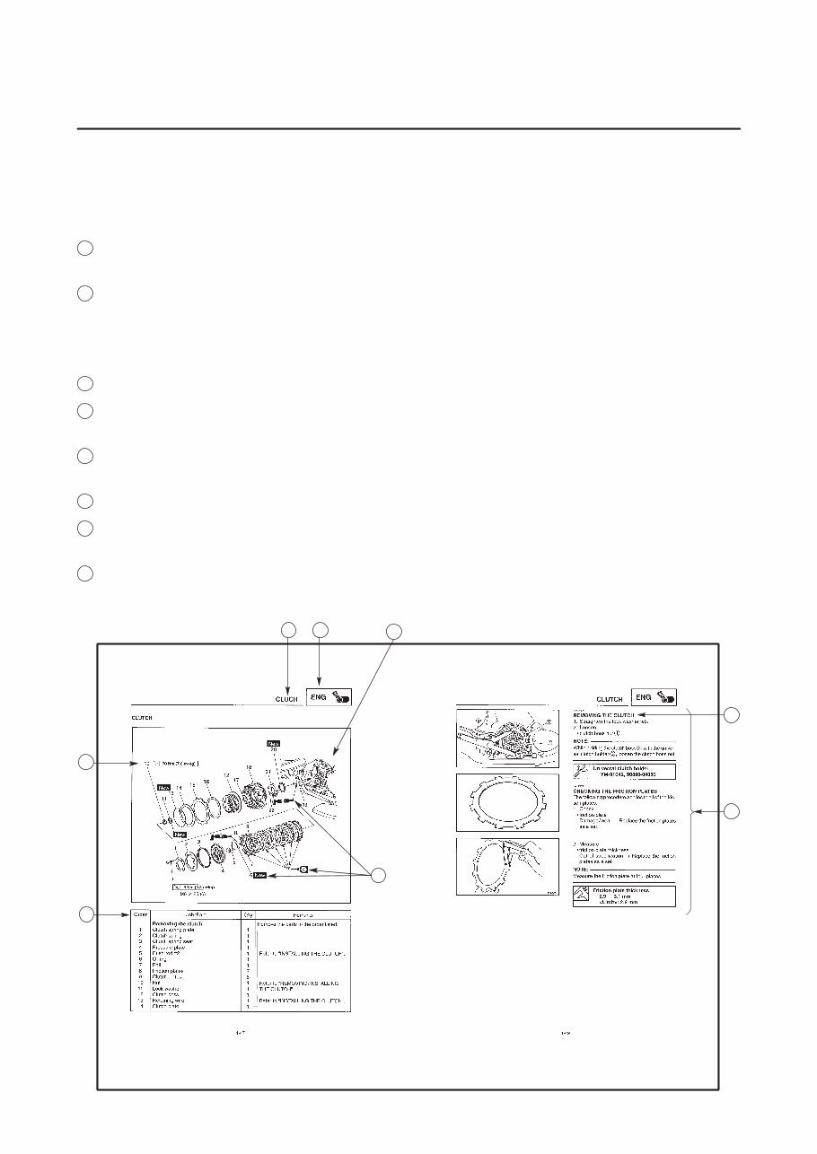
1 2 4 5 7 3 8 6 EAS00007 HOW TO USE THIS MANUAL This manual is intended as a handy, easy-to-read reference book for the mechanic. Comprehensive explanations of all installation, removal, disassembly, assembly, repair and inspection procedures are laid out with the individual steps in sequential order. 1 The manual is divided into chapters. An abbreviation and symbol in the upper right corner of each page indicate the current chapter. Refer to “SYMBOLS” on the following page. 2 Each chapter is divided into sections. The current section title is shown at the top of each page, except in Chapter 3 (“Periodic Inspections and Adjustments”), where the sub-section title(-s) appear. (In Chapter 3, “Periodic Inspection and Adjustments”, the sub-section title appears at the top of each page, instead of the section title.) 3 Sub-section titles appear in smaller print than the section title. 4 To help identify parts and clarify procedure steps, there are exploded diagrams at the start of each removal and disassembly section. 5 Numbers are given in the order of the jobs in the exploded diagram. A circled number indicates a disassembly step. 6 Symbols indicate parts to be lubricated or replaced (see “SYMBOLS”). 7 A job instruction chart accompanies the exploded diagram, providing the order of jobs, names of parts, notes in jobs, etc. 8 Jobs requiring more information (such as special tools and technical data) are described sequen- tially.
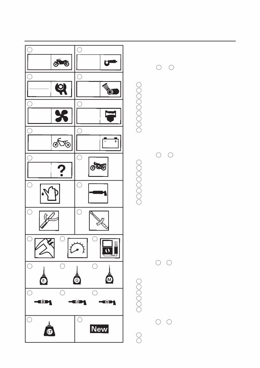
22 1 3 5 7 9 2 4 8 6 24 25 23 21 19 20 18 16 17 15 14 13 11 12 10 GEN INFO SPEC ENG CARB ELEC CHAS COOL CHK ADJ TRBL SHTG EAS00008 SYMBOLS The following symbols are not relevant to every vehicle. Symbols 1 to 9 indicate the subject of each chapter. 1 General information 2 Specifications 3 Periodic inspections and adjustments 4 Engine 5 Cooling system 6 Carburetor(-s) 7 Chassis 8 Electrical system 9 Troubleshooting Symbols 10 to 17 indicate the following. 10 Serviceable with engine mounted 11 Filling fluid 12 Lubricant 13 Special tool 14 Tightening torque 15 Wear limit, clearance 16 Engine speed 17 Electrical data Symbols 18 to 23 in the exploded diagrams indi- cate the types of lubricants and lubrication points. 18 Engine oil 19 Gear oil 20 Molybdenum disulfide oil 21 Wheel bearing grease 22 Lithium soap base grease 23 Molybdenum disulfide grease Symbols 24 to 25 in the exploded diagrams indi- cate the following: 24 Apply locking agent (LOCTITE R ) 25 Replace the part
GENERAL INFORMATION SPECIFICATIONS PERIODIC INSPECTIONS AND ADJUSTMENTS ENGINE COOLING SYSTEM CARBURETORS CHASSIS ELECTRICAL SYSTEM TROUBLESHOOTING GEN INFO 1 SPEC 2 3 ENG 4 COOL 5 CARB 6 CHAS 7 ELEC 8 TRBL SHTG 9 CHK ADJ EAS00012 TABLE OF CONTENTS
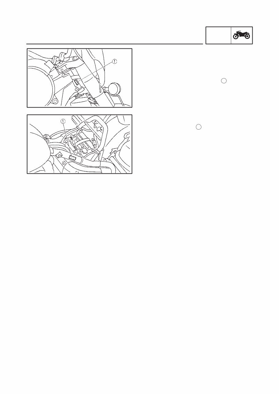
1-1 MOTORCYCLE IDENTIFICATION GEN INFO EAS00014 GENERAL INFORMATION MOTORCYCLE IDENTIFICATION EAS00017 VEHICLE IDENTIFICATION NUMBER The vehicle identification number 1 is stamped into the right side of the steering head. EAS00018 MODEL CODE The model code label 1 is affixed to the frame. This information will be needed to order spare parts.
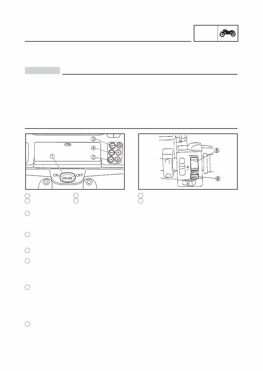
1-2 FEATURES GEN INFO CAUTION: 3 “SET” indicator light 4 “RES” indicator light 5 Cruise control switch 6 “CANCEL” switch EAS00019 FEATURES CRUISE CONTROL This motorcycle is equipped with cruise control which designed to maintain a set speed. S Giving a severe load like using as a trailer / tractor or driving on a steep slope could remove the cruise control. S Do not set the cruise control while idling the rear tires for the preparation. S Do not disassemble the vacuum pump. S Never remove the cruise control actuator rubber cover. When putting it back, bolts or other parts will be caught and the cruise control wire can be locked. S Do not remove the air cleaner cover of the vacuum pump in order not to cause a malfunction in cancellation of the cruise control by dirt, trash etc. S Do not drive without holding the steering wheel whether the cruise control is ON or OFF. 1 “CRUISE” switch 2 “ON” indicator light Cruise control switch functions 1 “CRUISE” switch Push this switch to “ON” when the cruise control system is preset. The “ON” indicator light will come on. Once the switch is released it will return to the center (Hold) position. To cancel the cruise control system, push the switch to “OFF” or main switch to the “OFF” position. 2 “ON” indicator light This indicator light comes on when the cruise control systems preset (when “ON” is selected by the “CRUISE” switch). 3 “SET” indicator light This indicator light comes on when the motorcycle is operating at a set speed. 4 “RES” indicator light This light comes on when the set speed, which is cancelled by any steps, is memorized and when the operating speed is in the range of approx. 50-130 km / h. If the resume system is operated while this light is on, it continues flashing until the speed returns to that memorized. 5 Cruise control switch This switch is capable of the following controls. Refer to the “Operation chart” for details. Set speed ride Minute adjustment of set speed Consecutive adjustment of set speed “RESUME” system 6 “CANCEL” switch Push this switch to cancel the set speed ride in the cruise control system.
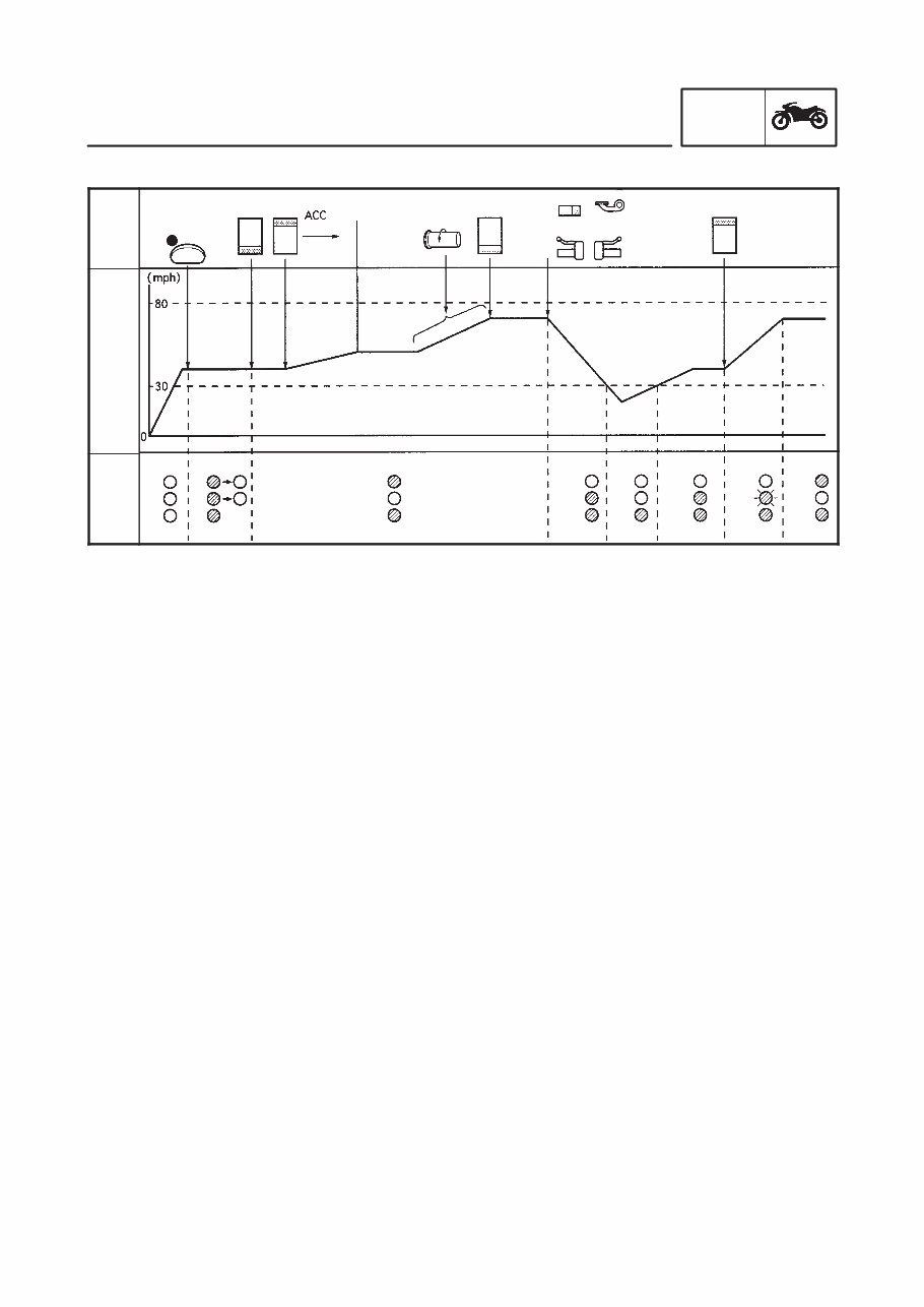
1-3 FEATURES GEN INFO SET CRUISE SET RES ON (After1.4sec) SET RES ON SET RES ON Flash Out of range Out of range Mannual acceleration cancel Rear brake Clutch SET Front brake Resume Cruise SW ON Operation chart Opera- tion Speed Indica- tor Cruise control function 1) The cruise control can only be activated when riding in 4th, 5th gear and traveling between the speed of 50 and 130 km / h. 2) To operate the system, the “CRUISE” switch should be turned “ON”. 3) When push the cruise control switch to “SET”, the cruise control system will be set the set speed. 4) By pushing (in shorter than 0.5 seconds), the control switch in the direction of either “ACC” or “DEC”, the set speed can be changed in increments or decrements of approximately 1.6 km / h. 5) If the control switch is held in the “ACC” or “DEC” position (longer than 0.5 seconds), the speed can be successively increased or decreased slowly. 6) The cruise control will be deactivated if the front or rear brake is applied or if the clutch is disengaged or if the “CANCEL” switch is pushed. 7) After canceling, the speed is returned to the one set before the cancellation by pushing the control switch once in the “RES” direction. 8) Auto cruise function is canceled; a. In case of current speed drops 8 km / h less than the originally set speed. b. In case of gear position is moved to gears other than of 4th, 5th. c. In case of systems fines any faulty signal in the following systems. S Control unit S Actuator cable S Logical error in cut off signal S Error signal in speed sensor signal S Error signal in engine revolution S Cruise control switch lead (“SET” / “RES”) 9) When main switch is cut off once, “resume” is canceled.
This Workshop Repair Service Manual is a comprehensive guide for the 1998-2010 Yamaha XVZ13TFL(C), XVZ13CCT(C) Royal Star Venture/Midnight Venture/Tour Deluxe Motorcycle. It is designed to assist in the repair, maintenance, rebuilding, refurbishing, and restoration of the vehicle. The manual covers all diagnostic and repair procedures in great detail, making it equally useful for professional technicians and DIY enthusiasts.
Key features of this manual include:
Complete coverage of all repair procedures from A-Z
High-quality photos, illustrations, and diagrams
Compatibility with all versions of Windows, Mac, and Linux
The manual includes detailed information on the following:
General Information
Engine (including mechanical, lubrication, cooling, control, fuel, and exhaust systems)
Transmission/Transaxle (covering clutch, manual transaxle, and automatic transaxle)
Driveline/Axle (front and rear axle)
Suspension (front and rear suspension, road wheels, and tires)
Brakes (including the brake system, parking brake system, and brake control system)
Steering (power steering system and steering system)
Restraints (seat belts and supplemental restraint system)
Body (body, lock & security system, glasses, window system & mirrors, roof, exterior & interior, instrumental panel, and seat)
Air Conditioner (air conditioner system)
Electrical (wiring diagrams, starting & charging system, lighting system, driver information system, wiper, washer & horn, body control system, lan system, audio visual, navigation & telephone system, auto cruise control system, power supply, ground & circuit elements)
Maintenance
Alphabetical Index
This Workshop Repair Service Manual is an invaluable resource for anyone working on the 1998-2010 Yamaha XVZ13TFL(C), XVZ13CCT(C) Royal Star Venture/Midnight Venture/Tour Deluxe Motorcycle, providing easy access to comprehensive repair procedures and technical information.
Recently Viewed
5,521,897Happy Clients
2,594,462eManuals
1,120,453Trusted Sellers
15Years in Business
Price:
Actual Price:
1998-2010 Yamaha XVZ13TFL(C), XVZ13CCT(C) Royal Star Venture/Midnight Venture/Tour Deluxe Motorcycle Workshop Repair Service Man

, XVZ13CCT(C) Royal Star Venture/Midnight Venture/Tour Deluxe Motorcycle Workshop Repair Service Man")