

2009 Yamaha VIRAGO 250 / V STAR 250 Motorcycle Service Manual
What's Included?
Fast Download Speeds
Online & Offline Access
Access PDF Contents & Bookmarks
Full Search Facility
Print one or all pages of your manual

LIT-11616-19-23 2UJ-28197-12
XV250V(C)
SUPPLEMENTARY
SERVICE MANUAL
FOREWORD
This Supplementary Service Manual has been prepared to introduce new service and data for the
XV250V(C). For complete service information procedures it is necessary to use this Supplementary
Service Manual together with the following manual.
XV250U/XV250UC SERVICE MANUAL: LIT-11616-06-18 (2UJ-28197-10)
XV250G/XV250GC SUPPLEMENTARY SERVICE MANUAL:
LIT-11616-09-69 (2UJ-28197-11)
XV250V(C)
SUPPLEMENTARY
SERVICE MANUAL
©2005 by Yamaha Motor Corporation, U.S.A.
First edition, October 2005
All rights reserved.
Any reproduction or unauthorized use
without the written permission of
Yamaha Motor Corporation, U.S.A.
is expressly prohibited.
Printed in U.S.A.
LIT-11616-19-23
EAS00003
NOTICE
This manual was produced by the Yamaha Motor Company, Ltd. primarily for use by Yamaha
dealers and their qualified mechanics. It is not possible to include all the knowledge of a mechanic
in one manual. Therefore, anyone who uses this book to perform maintenance and repairs on
Yamaha vehicles should have a basic understanding of mechanics and the techniques to repair
these types of vehicles. Repair and maintenance work attempted by anyone without this knowledge
is likely to render the vehicle unsafe and unfit for use.
This model has been designed and manufactured to perform within certain specifications in regard
to performance and emissions. Proper service with the correct tools is necessary to ensure that the
vehicle will operate as designed. If there is any question about a service procedure, it is imperative
that you contact a Yamaha dealer for any service information changes that apply to this model. This
policy is intended to provide the customer with the most satisfaction from his vehicle and to conform
with federal environmental quality objectives.
Yamaha Motor Company, Ltd. is continually striving to improve all of its models. Modifications and
significant changes in specifications or procedures will be forwarded to all authorized Yamaha
dealers and will appear in future editions of this manual where applicable.
NOTE:
• This Service Manual contains information regarding periodic maintenance to the emission control
system. Please read this material carefully.
• Designs and specifications are subject to change without notice.
EAS00004
IMPORTANT MANUAL INFORMATION
Particularly important information is distinguished in this manual by the following.
The Safety Alert Symbol means ATTENTION! BECOME ALERT! YOUR
SAFETY IS INVOLVED!
Failure to follow WARNING instructions could result in severe injury or death
to the vehicle operator, a bystander or a person checking or repairing the
vehicle.
A CAUTION indicates special precautions that must be taken to avoid
damage to the vehicle.
A NOTE provides key information to make procedures easier or clearer.
WARNING
CAUTION:
NOTE:
EAS00007
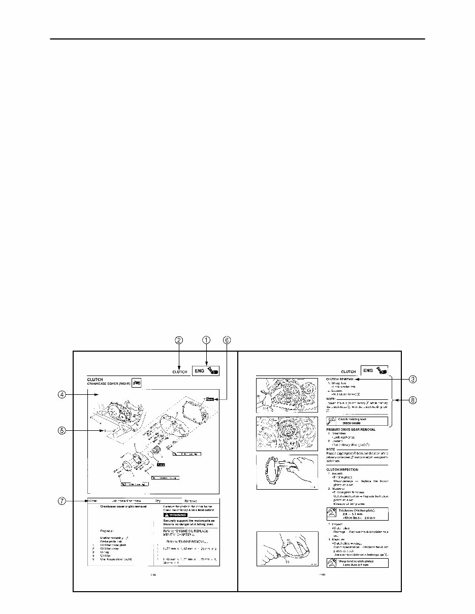
HOW TO USE THIS MANUAL
This manual is intended as a handy, easy-to-read reference book for the mechanic. Comprehensive
explanations of all installation, removal, disassembly, assembly, repair and check procedures are
laid out with the individual steps in sequential order.
1 The manual is divided into chapters. An abbreviation and symbol in the upper right corner of
each page indicate the current chapter.
Refer to “SYMBOLS”.
2 Each chapter is divided into sections. The current section title is shown at the top of each page,
except in Chapter 3 (“PERIODIC CHECKS AND ADJUSTMENTS”), where the sub section title(s)
appears.
3 Sub section titles appear in smaller print than the section title.
4 To help identify parts and clarify procedure steps, there are exploded diagrams at the start of
each removal and disassembly section.
5 Numbers are given in the order of the jobs in the exploded diagram. A circled number indicates a
disassembly step.
6 Symbols indicate parts to be lubricated or replaced.
Refer to “SYMBOLS”.
7 A job instruction chart accompanies the exploded diagram, providing the order of jobs, names of
parts, notes in jobs, etc.
8 Jobs requiring more information (such as special tools and technical data) are described sequen-
tially.
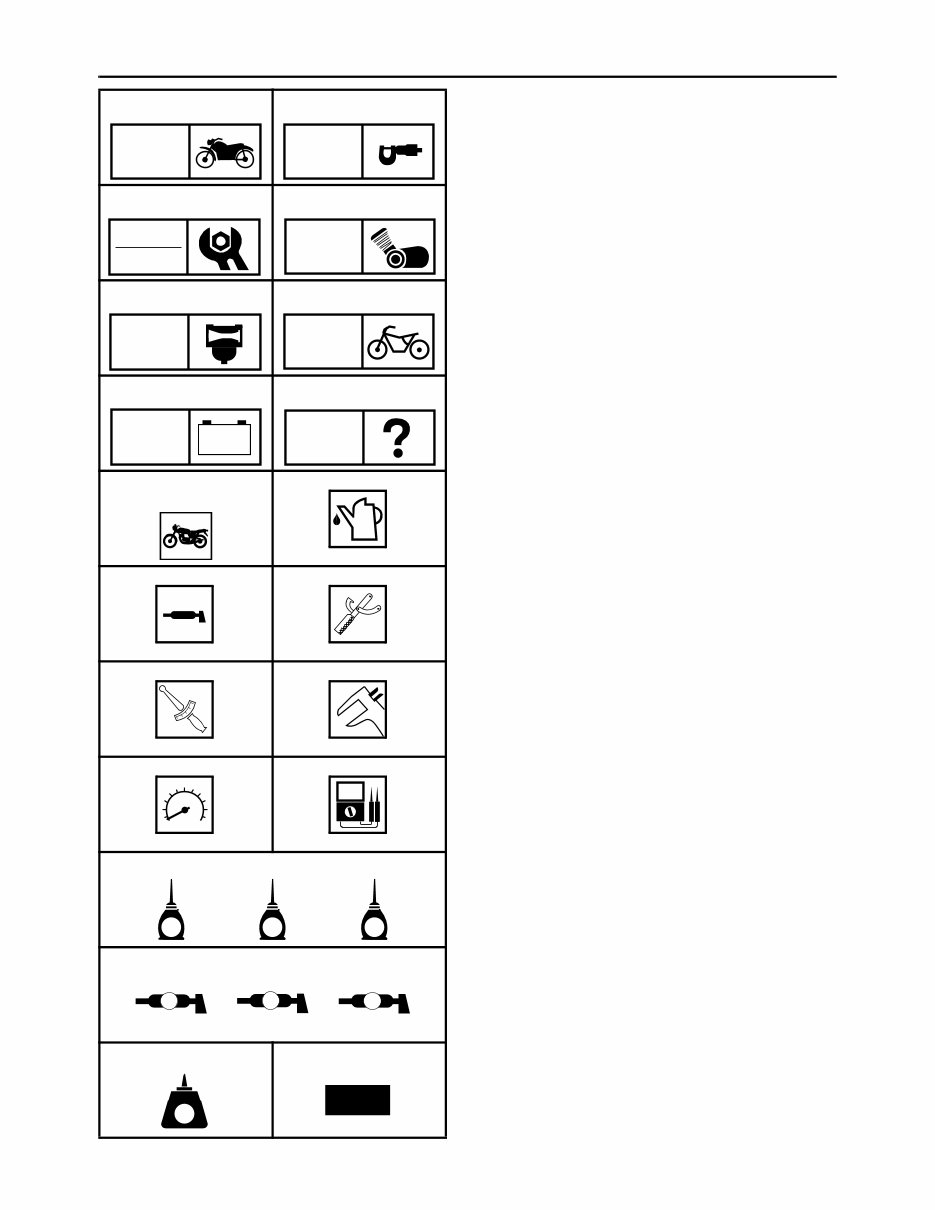
SYMBOLS
The following symbols are not relevant to
every vehicle.
Symbols 1 to 8 indicate the subject of each
chapter.
1 General information
2 Specifications
3 Periodic checks and adjustments
4 Engine
5 Carburetor
6 Chassis
7 Electrical system
8 Troubleshooting
Symbols 9 to F indicate the following.
9 Serviceable with engine mounted
0 Filling fluid
A Lubricant
B Special tool
C Tightening torque
D Wear limit, clearance
E Engine speed
F Electrical data
Symbols G to L in the exploded diagrams
indicate the types of lubricants and lubrication
points.
G Engine oil
H Gear oil
I Molybdenum disulfide oil
J Wheel bearing grease
K Lithium-soap-based grease
L Molybdenum disulfide grease
Symbols M to N in the exploded diagrams
indicate the following.
M Apply locking agent (LOCTITE
®
).
N Replace the part.
1 2
3 4
5 6
7 8
9 0
A B
C D
E F
G H I
J K L
M N
GEN
INFO
SPEC
CHK
ADJ
ENG
CARB
CHAS
– +
ELEC
TRBL
SHTG
T
R
.
.
E G M
B
LS M
LT
New

CONTENTS
SPECIFICATIONS .............................................................................................. 1
GENERAL SPECIFICATIONS ..................................................................... 1
ENGINE SPECIFICATIONS ......................................................................... 1
CHASSIS SPECIFICATIONS ....................................................................... 8
ELECTRICAL SPECIFICATIONS .............................................................. 10
CABLE ROUTING ...................................................................................... 12
PERIODIC CHECKS AND ADJUSTMENTS .................................................... 21
INTRODUCTION ........................................................................................ 21
PERIODIC MAINTENANCE CHART FOR THE EMISSION CONTROL
SYSTEM .................................................................................................... 21
GENERAL MAINTENANCE AND LUBRICATION CHART ........................ 22
CARBURETOR................................................................................................. 24
AIR INDUCTION SYSTEM ......................................................................... 24
AIR INJECTION ................................................................................... 24
AIR CUT-OFF VALVE.......................................................................... 24
AIR CUT-OFF VALVE ASSEMBLY ..................................................... 25
CHECKING THE AIR INDUCTION SYSTEM ...................................... 27
CANISTER (FOR CALIFORNIA ONLY) ..................................................... 28
CHECKING THE ROLLOVER VALVE ................................................. 29
CHECKING THE CANISTER............................................................... 29
– 1 –
SPEC
SPECIFICATIONS
GENERAL SPECIFICATIONS
ENGINE SPECIFICATIONS
Item Standard Limit
Model code 2UJN (USA)
3BGF (California)
----
----
Weight
Wet (with oil and a full fuel tank) 147 kg (324 lb) (USA)
148 kg (326 lb) (California)
----
----
Maximum load (total of cargo, rider,
passenger, and accessories)
196 kg (432 lb) (USA)
195 kg (430 lb) (California)
----
----
Item Standard Limit
Fuel
Recommended fuel Unleaded gasoline only ----
Fuel tank capacity 9.5 L (2.09 Imp gal, 2.51 US gal) (USA)
9.2 L (2.02 Imp gal, 2.43 US gal) (Califor-
nia)
----
----
Fuel reserve amount 2.6 L (0.57 Imp gal, 0.69 US gal) ----
Engine oil
Lubrication system Wet sump ----
Recommended oil
YAMALUBE 4, SAE10W30 or SAE20W40
API service SE, SF, SG type or higher
----
----
Quantity
Total amount 1.8 L (1.58 Imp qt, 1.90 US qt) ----
Without oil filter element replace-
ment
1.4 L (1.23 Imp qt, 1.48 US qt) ----
With oil filter element replacement 1.6 L (1.41 Imp qt, 1.69 US qt) ----
10˚ 30˚ 50˚ 70˚ 90˚ 110˚ 0˚ 130˚F
–10˚ 0˚ 10˚ 20˚ 30˚ 40˚ –20˚ 50˚C
YAMALUBE 4 (10W30) or
SAE 10W30
YAMALUBE 4 (20W40) or
SAE 20W40
GENERAL SPECIFICATIONS/
ENGINE SPECIFICATIONS
– 2 –
SPEC
ENGINE SPECIFICATIONS
Oil pump
Oil pump type Trochoid ----
Inner-rotor-to-outer-rotor-tip clear-
ance
Less than 0.15 mm (0.0059 in) 0.23 mm
(0.0091 in)
Outer-rotor-to-oil-pump-housing
clearance
0.03 ~ 0.09 mm (0.0012 ~ 0.0035 in) 0.16 mm
(0.0063 in)
Relief valve opening pressure 450 ~ 550 kPa
(4.5 ~ 5.5 kgf/cm
2
, 65.3 ~ 79.8 psi)
----
Pressure check location CRANKCASE BOLT ----
Cylinder head
Volume 14.10 ~ 14.50 cm
3
(0.86 ~ 0.88 cu.in) ----
Max warpage ---- 0.03 mm
(0.0012 in)
Camshafts
Drive system Chain drive (left) ----
Camshaft cap inside diameter 22.000 ~ 22.021 mm (0.8661 ~ 0.8670 in) ----
Camshaft journal diameter 21.960 ~ 21.980 mm (0.8646 ~ 0.8654 in) ----
Camshaft-journal-to-camshaft cap
clearance
0.020 ~ 0.061 mm (0.0008 ~ 0.0024 in) 0.08 mm
(0.0031 in)
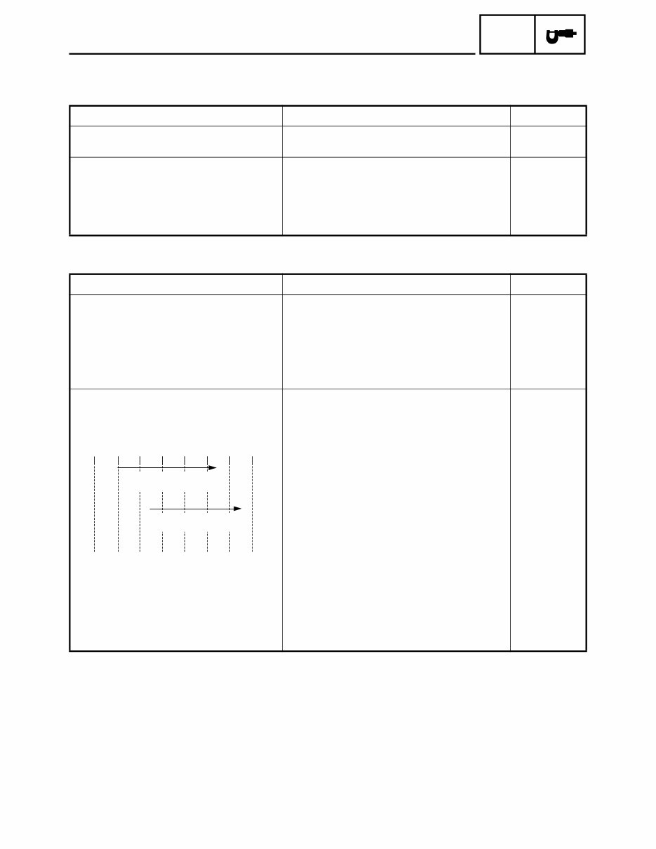
Intake camshaft lobe dimensions
Measurement A 26.190 mm (1.0311 in) 26.090 mm
(1.0272 in)
Measurement B 21.045 mm (0.8285 in) (Cylinder #1)
21.087 mm (0.8302 in) (Cylinder #2)
20.945 mm
(0.8246 in)
20.987 mm
(0.8263 in)
Item Standard Limit
A
B
– 3 –
SPEC
ENGINE SPECIFICATIONS
Exhaust camshaft lobe dimensions
Measurement A 26.190 mm (1.0311 in) 26.090 mm
(1.0272 in)
Measurement B 21.087 mm (0.8302 in) (Cylinder #1) 20.987 mm
(0.8263 in)
21.045 mm (0.8285 in) (Cylinder #2) 20.945 mm
(0.8246 in)
Camshaft runout limit ---- 0.015 mm
(0.0006 in)
Valves, valve seats, valve guides
Valve clearance (cold)
Intake 0.08 ~ 0.12 mm (0.0032 ~ 0.0047 in) ----
Exhaust 0.10 ~ 0.14 mm (0.0039 ~ 0.0055 in) ----
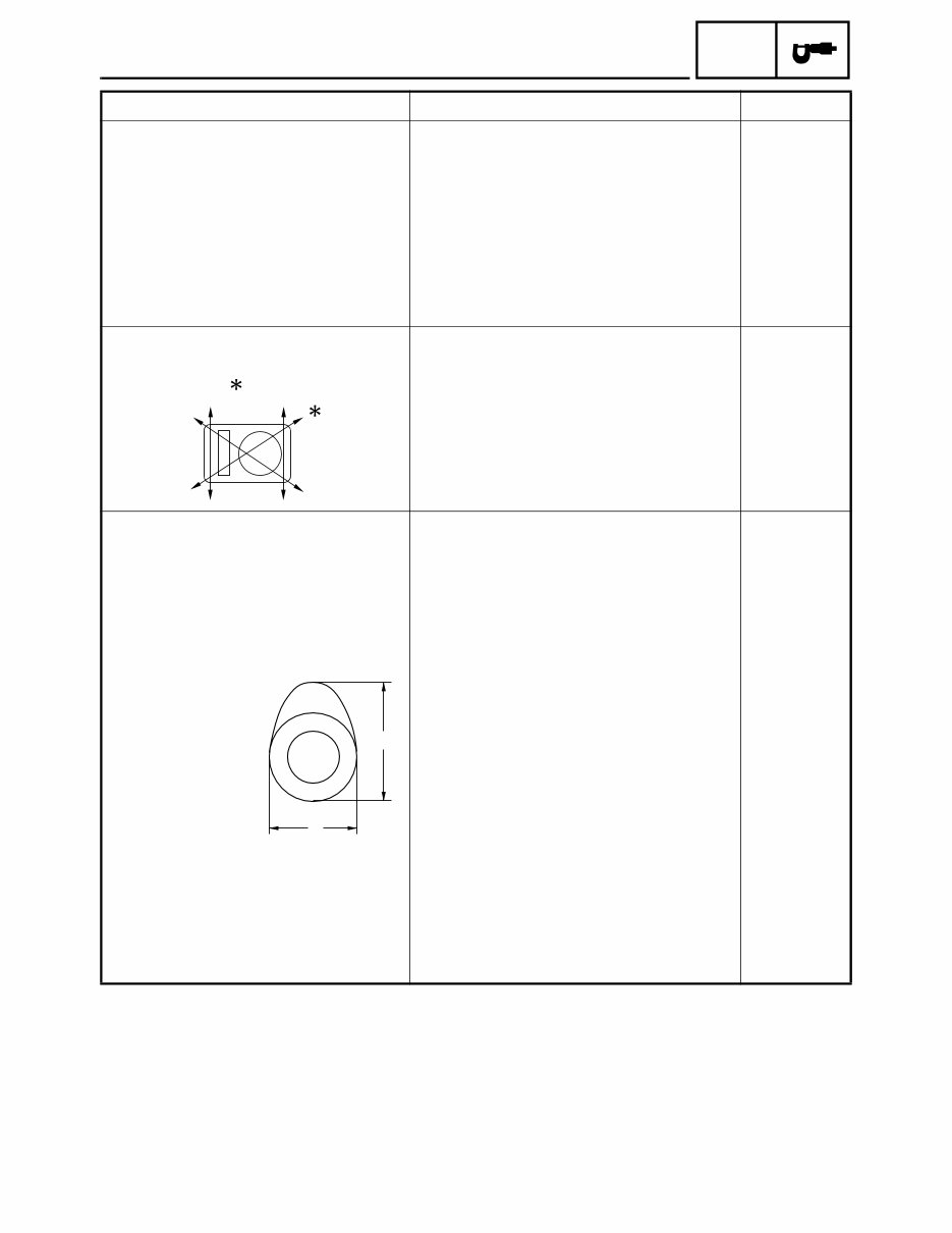
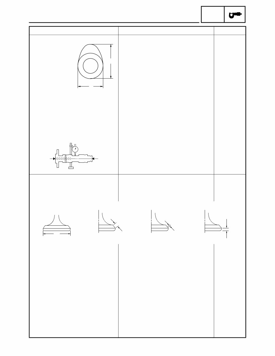
Valve dimensions
Valve head diameter A
Intake 25.90 ~ 26.10 mm (1.0197 ~ 1.0276 in) ----
Exhaust 21.90 ~ 22.10 mm (0.8622 ~ 0.8701 in) ----
Valve face width B
Intake 1.40 ~ 3.20 mm (0.0551 ~ 0.1260 in) ----
Exhaust 1.70 ~ 2.80 mm (0.0669 ~ 0.1102 in) ----
Valve seat width C
Intake 0.9 ~ 1.1 mm (0.0354 ~ 0.0433 in) 1.6 mm
(0.06 in)
Exhaust 0.9 ~ 1.1 mm (0.0354 ~ 0.0433 in) 1.6 mm
(0.06 in)
Valve margin thickness D
Intake 0.4 ~ 0.8 mm (0.0157 ~ 0.0315 in) ----
Exhaust 0.8 ~ 1.2 mm (0.0315 ~ 0.0472 in) ----
Item Standard Limit
A
B
B
C
D
A
Head Diameter Face Width Seat Width Margin Thickness
– 4 –
SPEC
ENGINE SPECIFICATIONS
Valve stem diameter
Intake 4.975 ~ 4.990 mm (0.1959 ~ 0.1965 in) 4.950 mm
(0.1949 in)
Exhaust 4.960 ~ 4.975 mm (0.1953 ~ 0.1959 in) 4.953 mm
(0.1950 in)
Valve guide inside diameter
Intake 5.000 ~ 5.012 mm (0.1969 ~ 0.1973 in) 5.030 mm
(0.1980 in)
Exhaust 5.000 ~ 5.012 mm (0.1969 ~ 0.1973 in) 5.030 mm
(0.1980 in)
Valve-stem-to-valve-guide clearance
Intake 0.010 ~ 0.037 mm (0.0004 ~ 0.0015 in) 0.080 mm
(0.0032 in)
Exhaust 0.025 ~ 0.052 mm (0.0010 ~ 0.0020 in) 0.100 mm
(0.0039 in)
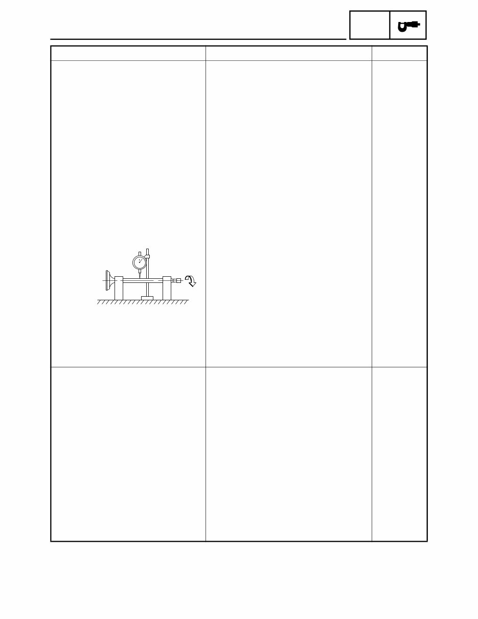
Valve stem runout ---- 0.020 mm
(0.0008 in)
Valve seat width
Intake 0.9 ~ 1.1 mm (0.0354 ~ 0.0433 in) 1.6 mm
(0.06 in)
Exhaust 0.9 ~ 1.1 mm (0.0354 ~ 0.0433 in) 1.6 mm
(0.06 in)
Valve springs
Free length
Intake 39.91 mm (1.57 in) 38.91 mm
(1.53 in)
Exhaust 39.91 mm (1.57 in) 38.91 mm
(1.53 in)
Installed length (valve closed)
Intake 25.70 mm (1.01 in) ----
Exhaust 25.70 mm (1.01 in) ----
Spring rate (K1)
Intake 10.32 N/mm (1.05 kgf/mm, 58.93 lb/in) ----
Exhaust 10.32 N/mm (1.05 kgf/mm, 58.93 lb/in) ----
Spring rate (K2)
Intake 13.40 N/mm (1.37 kgf/mm, 76.51 lb/in) ----
Exhaust 13.40 N/mm (1.37 kgf/mm, 76.51 lb/in) ----
Item Standard Limit
You're Reading a Preview
What's Included?
Fast Download Speeds
Online & Offline Access
Access PDF Contents & Bookmarks
Full Search Facility
Print one or all pages of your manual
$35.99
$46.99
Viewed 47 Times Today


Secure transaction
What's Included?
Fast Download Speeds
Online & Offline Access
Access PDF Contents & Bookmarks
Full Search Facility
Print one or all pages of your manual
$35.99
$46.99
This manual covers the 2009 Yamaha VIRAGO 250 / V STAR 250 motorcycle service manual. It is a comprehensive guide used by professional mechanics and DIY enthusiasts for repairs and maintenance.


