

2006 Yamaha ROADLINER / S / MIDNIGHT / STRATOLINER / S / MIDNIGHT Motorcycle Service Manual
What's Included?
Fast Download Speeds
Online & Offline Access
Access PDF Contents & Bookmarks
Full Search Facility
Print one or all pages of your manual

Fix it like a Pro

How to use this Service Manual
In the bookmarks to the left you will find different
segments of this manual:
Service Manual
This is the standard manual for this vehicle. Use this
segment as your major point of reference and information.
Supplementary Service Manual (if available)
These segments are updates and additions to the standard
service manual. They are added as needed when certain
changes are made to the model. Be sure to check these
for additional information that may be lacking from the
regular service manual.
EAS20090
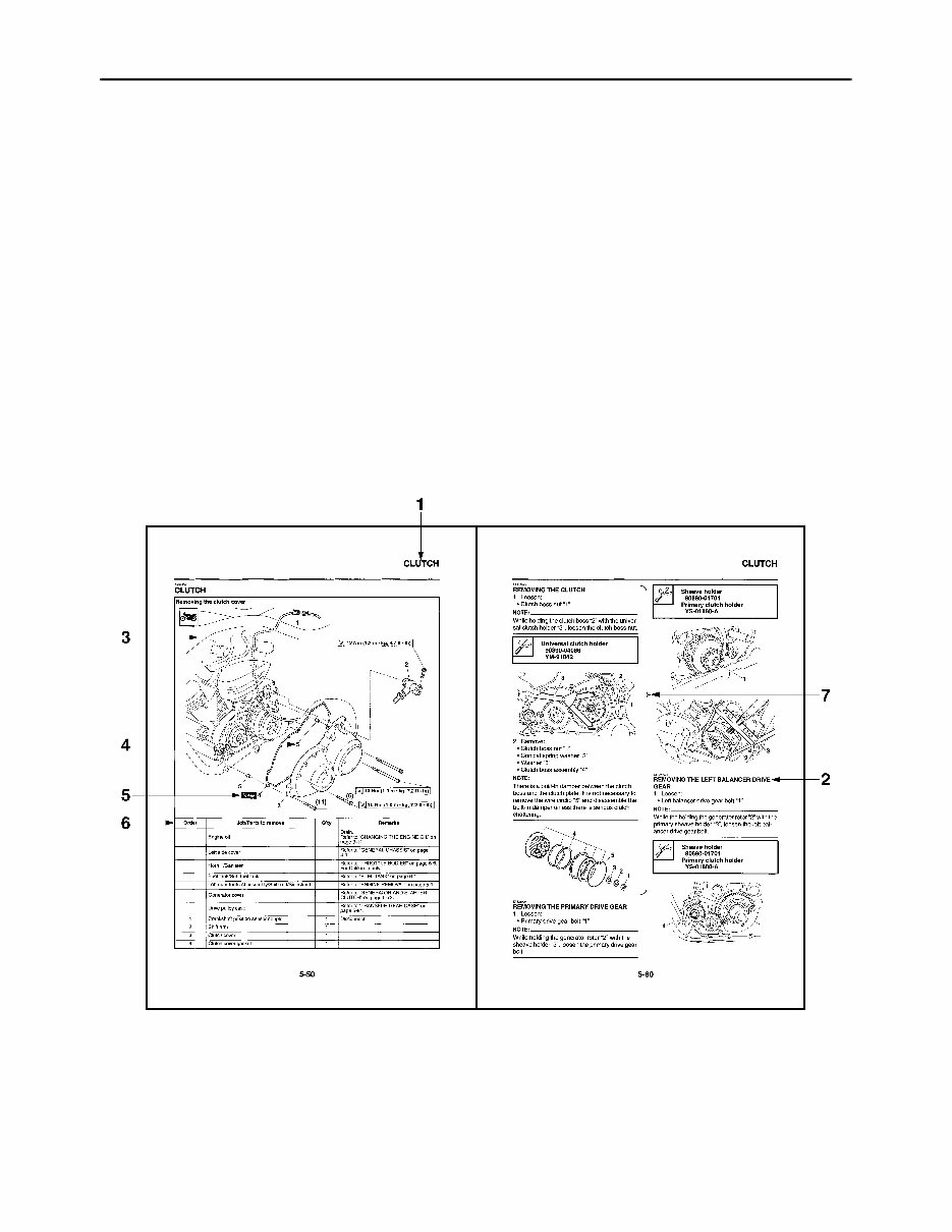
HOW TO USE THIS MANUAL
This manual is intended as a handy, easy-to-read reference book for the mechanic. Comprehensive
explanations of all installation, removal, disassembly, assembly, repair and check procedures are laid
out with the individual steps in sequential order.
• The manual is divided into chapters and each chapter is divided into sections. The current section title
is shown at the top of each page “1”.
• Sub-section titles “2” appear in smaller print than the section title.
• To help identify parts and clarify procedure steps, there are exploded diagrams “3” at the start of each
removal and disassembly section.
• Numbers “4” are given in the order of the jobs in the exploded diagram. A number indicates a disas-
sembly step.
• Symbols “5” indicate parts to be lubricated or replaced.
Refer to “SYMBOLS”.
• A job instruction chart “6” accompanies the exploded diagram, providing the order of jobs, names of
parts, notes in jobs, etc.
• Jobs “7” requiring more information (such as special tools and technical data) are described sequen-
tially.
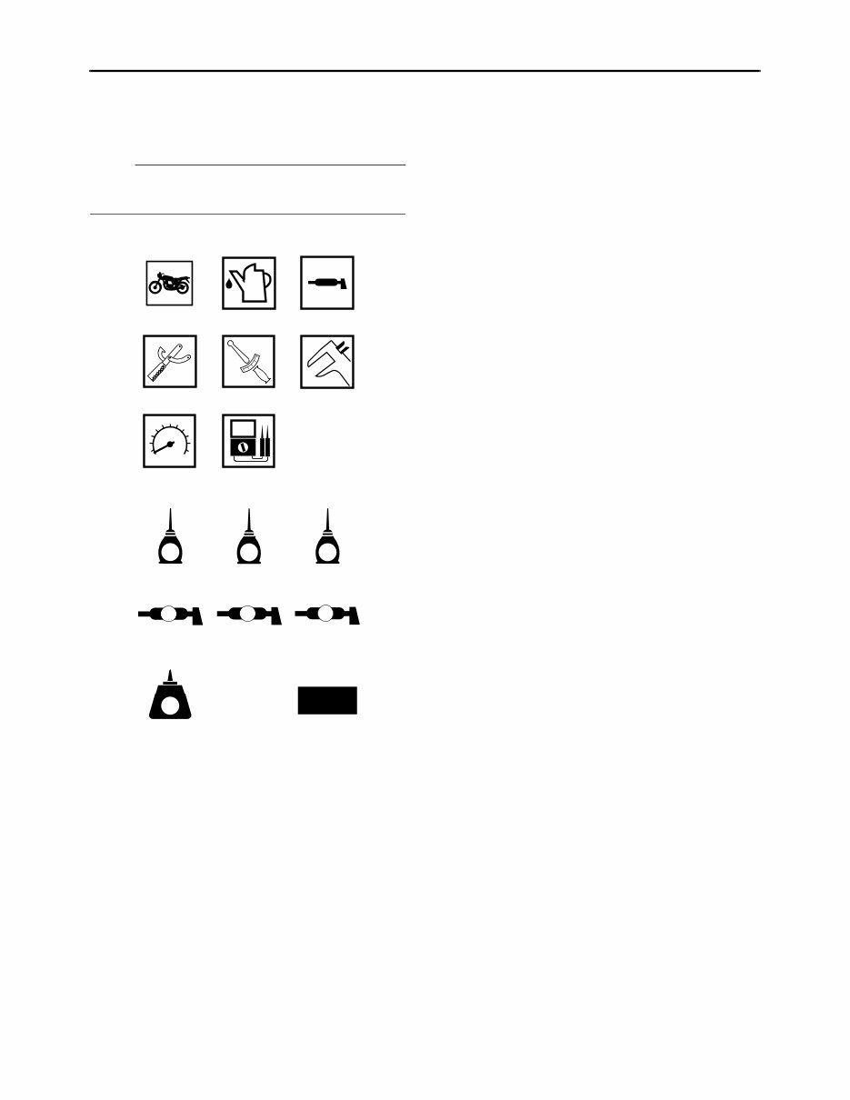
EAS20100
SYMBOLS
The following symbols are used in this manual
for easier understanding.
NOTE:
The following symbols are not relevant to every
vehicle.
G M E
B LS M
9 10 11
12 13 14
15 16
LT
New
T
R
.
.
1 2 3
4 5 6
7 8
1. Serviceable with engine mounted
2. Filling fluid
3. Lubricant
4. Special tool
5. Tightening torque
6. Wear limit, clearance
7. Engine speed
8. Electrical data
9. Engine oil
10. Gear oil
11.Molybdenum-disulfide oil
12. Wheel-bearing grease
13.Lithium-soap-based grease
14.Molybdenum-disulfide grease
15.Apply locking agent (LOCTITE
®
)
16. Replace the part
EAS20110
TABLE OF CONTENTS
GENERAL INFORMATION
1
SPECIFICATIONS
2
PERIODIC CHECKS AND ADJUSTMENTS
3
CHASSIS
4
ENGINE
5
FUEL SYSTEM
6
ELECTRICAL SYSTEM
7
TROUBLESHOOTING
8

1
GENERAL INFORMATION
IDENTIFICATION ............................................................................................ 1-1
VEHICLE IDENTIFICATION NUMBER..................................................... 1-1
MODEL LABEL ......................................................................................... 1-1
FEATURES ..................................................................................................... 1-2
OUTLINE OF THE FI SYSTEM................................................................. 1-2
FI SYSTEM ............................................................................................... 1-3
INSTRUMENT FUNCTIONS..................................................................... 1-4
IMPORTANT INFORMATION ......................................................................... 1-8
PREPARATION FOR REMOVAL AND DISASSEMBLY .......................... 1-8
REPLACEMENT PARTS .......................................................................... 1-8
GASKETS, OIL SEALS AND O-RINGS .................................................... 1-8
LOCK WASHERS/PLATES AND COTTER PINS..................................... 1-8
BEARINGS AND OIL SEALS.................................................................... 1-9
CIRCLIPS.................................................................................................. 1-9
CHECKING THE CONNECTIONS ................................................................ 1-10
SPECIAL TOOLS .......................................................................................... 1-11
IDENTIFICATION
1-1
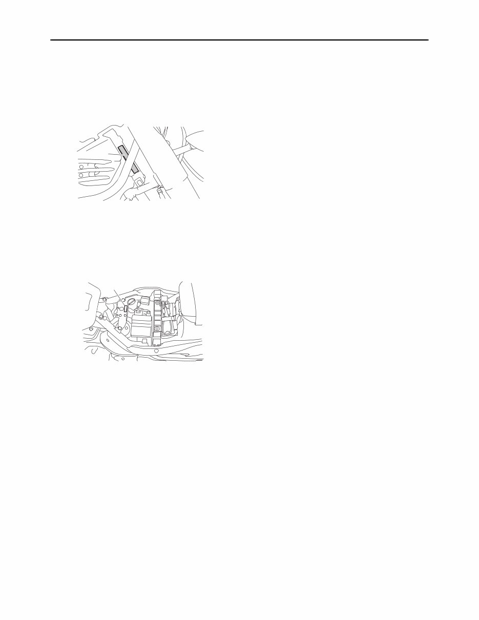
EAS20130
IDENTIFICATION
EAS20140
VEHICLE IDENTIFICATION NUMBER
The vehicle identification number “1” is stamped
into the right side of the steering head pipe.
EAS20150
MODEL LABEL
The model label “1” is affixed to the frame under
the rider seat. This information will be needed to
order spare parts.
1
1
FEATURES
1-2
EAS20170
FEATURES
ET1D71017
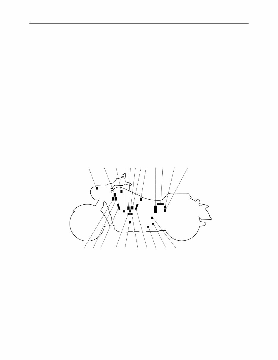
OUTLINE OF THE FI SYSTEM
The main function of a fuel supply system is to provide fuel to the combustion chamber at the optimum
air-fuel ratio in accordance with the engine operating conditions and the atmospheric temperature. In
the conventional carburetor system, the air-fuel ratio of the mixture that is supplied to the combustion
chamber is created by the volume of the intake air and the fuel that is metered by the jet used in the
respective carburetor.
Despite the same volume of intake air, the fuel volume requirement varies by the engine operating con-
ditions, such as acceleration, deceleration, or operating under a heavy load. Carburetors that meter the
fuel through the use of jets have been provided with various auxiliary devices, so that an optimum air-
fuel ratio can be achieved to accommodate the constant changes in the operating conditions of the en-
gine.
As the requirements for the engine to deliver more performance and cleaner exhaust gases increase,
it becomes necessary to control the air-fuel ratio in a more precise and finely tuned manner. To accom-
modate this need, this model has adopted an electronically controlled fuel injection (FI) system, in place
of the conventional carburetor system. This system can achieve an optimum air-fuel ratio required by
the engine at all times by using a microprocessor that regulates the fuel injection volume according to
the engine operating conditions detected by various sensors.
The adoption of the FI system has resulted in a highly precise fuel supply, improved engine response,
better fuel economy, and reduced exhaust emissions.
1 2
20 21
3 4 5678 9 10 11 12
14 13 16 19 18 17 16 15
1. Air temperature sensor
2. ISC (idle speed control) unit
3. Cylinder-#2 intake air pressure sensor
4. Engine temperature sensor
5. Cylinder-#1 right ignition coil
6. Throttle position sensor
7. Cylinder-#1 left ignition coil
8. Cylinder-#1 intake air pressure sensor
9. Fuel pump
10. ECU (electronic control unit)
11.Relay unit (fuel pump relay)
12. EXUP servo motor
13. Speed sensor
14.O
2
sensor
15. Lean angle sensor
16. Spark plug
17. Injector #1
18.Crankshaft position sensor
19. Injector #2
20.Cylinder-#2 right ignition coil
21.Cylinder-#2 left ignition coil
FEATURES
1-3
ET1D71018
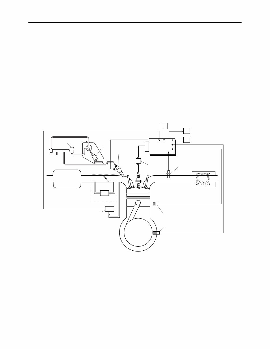
FI SYSTEM
The fuel pump delivers fuel to the fuel injector via the fuel filter. The pressure regulator maintains the
fuel pressure that is applied to the fuel injector at only 392 kPa (3.92 kg/cm², 55.7 psi). Accordingly,
when the energizing signal from the ECU energizes the fuel injector, the fuel passage opens, causing
the fuel to be injected into the intake manifold only during the time the passage remains open. There-
fore, the longer the length of time the fuel injector is energized (injection duration), the greater the vol-
ume of fuel that is supplied. Conversely, the shorter the length of time the fuel injector is energized
(injection duration), the lesser the volume of fuel that is supplied.
The injection duration and the injection timing are controlled by the ECU. Signals that are input from the
throttle position sensor, crankshaft position sensor, intake air pressure sensor, air temperature sensor,
engine temperature sensor, speed sensor and O
2
sensor enable the ECU to determine the injection
duration. The injection timing is determined through the signals from the crankshaft position sensor. As
a result, the volume of fuel that is required by the engine can be supplied at all times in accordance with
the driving conditions.
Illustration is for reference only.
15
A
1
2
3
4
C
5
8
7
6
10
11
12
13
14
B
#1 #2
9
1. Pressure regulator
2. Fuel pump
3. Fuel injector
4. Ignition coil
5. ECU (electronic control unit)
6. Air temperature sensor
7. ISC (idle speed control) unit
8. Throttle position sensor
9. O
2
sensor
10. Catalytic converter
11.Engine temperature sensor
12.Crankshaft position sensor
13.Intake air pressure sensor
14. Throttle body
15. Air filter case
A. Fuel system
B. Air system
C. Control system
FEATURES
1-4
ET1D71036
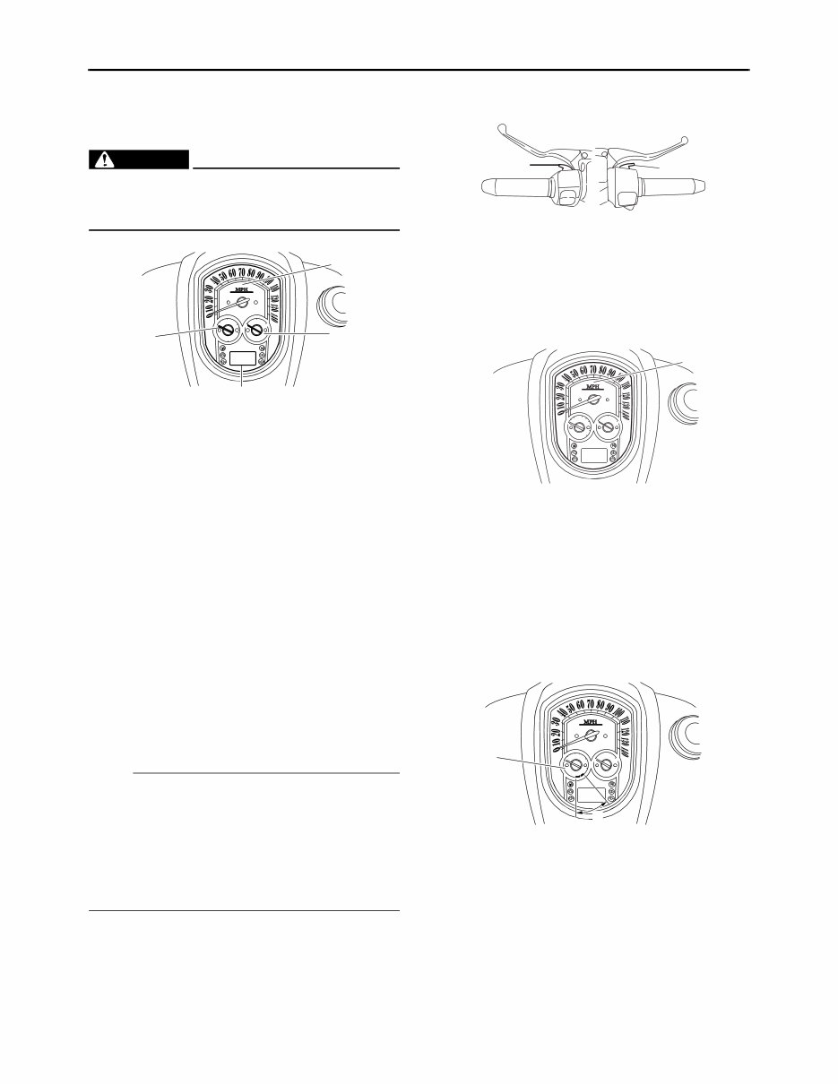
INSTRUMENT FUNCTIONS
Multi-function meter unit
WARNING
EW1D71008
Be sure to stop the vehicle before making
any setting changes to the multi-function
meter unit.
The multi-function meter unit is equipped with
the following:
• a speedometer (which shows the riding speed)
• a tachometer (which shows the engine speed)
• a fuel gauge
• an odometer (which shows the total distance
traveled)
• two tripmeters (which show the distance trav-
eled since they were last set to zero)
• a fuel reserve tripmeter (which shows the dis-
tance traveled on the fuel reserve)
• a clock
• a self-diagnosis device
• a brightness control mode
NOTE:
• Be sure to turn the key to “ON” before using the
“SELECT” and “RESET” switches.
• To switch the odometer, the tripmeters and the
fuel reserve tripmeter displays between kilo-
meters and miles, press the “SELECT” switch
for at least two seconds. (For USA and Califor-
nia only)
Speedometer
The speedometer shows the riding speed.
When the key is turned to “ON”, the speedome-
ter needle will sweep once across the speed
range and then return to zero in order to test the
electrical circuit.
Tachometer
The electric tachometer allows the rider to mon-
itor the engine speed and keep it within the ideal
power range.
When the key is turned to “ON”, the tachometer
needle will sweep once across the r/min range
and then return to zero r/min in order to test the
electrical circuit.
1. Speedometer
2. Fuel gauge
3. Odometer/tripmeter/fuel reserve
tripmeter/clock
4. Tachometer
2
3
1
4
1. “SELECT” switch
2. “RESET” switch
1. Speedometer
1. Tachometer
2. Tachometer red zone
2
1
1
2
1
You're Reading a Preview
What's Included?
Fast Download Speeds
Online & Offline Access
Access PDF Contents & Bookmarks
Full Search Facility
Print one or all pages of your manual
$35.99
Viewed 87 Times Today


Secure transaction
What's Included?
Fast Download Speeds
Online & Offline Access
Access PDF Contents & Bookmarks
Full Search Facility
Print one or all pages of your manual
$35.99
This manual covers the 2006 Yamaha ROADLINER / S / MIDNIGHT / STRATOLINER / S / MIDNIGHT motorcycle service manual. It is a comprehensive guide used by professional mechanics and DIY enthusiasts for repairs and maintenance.


