EAS00003 NOTICE This manual was produced by the Yamaha Motor Company, Ltd. primarily for use by Yamaha deal- ers and their qualified mechanics. It is not possible to include all the knowledge of a mechanic in one manual. Therefore, anyone who uses this book to perform maintenance and repairs on Yamaha vehicles should have a basic understanding of mechanics and the techniques to repair these types of vehicles. Repair and maintenance work attempted by anyone without this knowledge is likely to render the vehicle unsafe and unfit for use. This model has been designed and manufactured to perform within certain specifications in regard to performance and emissions. Proper service with the correct tools is necessary to ensure that the vehicle will operate as designed. If there is any question about a service procedure, it is imperative that you contact a Yamaha dealer for any service information changes that apply to this model. This policy is intended to provide the customer with the most satisfaction from his vehicle and to conform to federal environmental quality objectives. Yamaha Motor Company, Ltd. is continually striving to improve all of its models. Modifications and significant changes in specifications or procedures will be forwarded to all authorized Yamaha deal- ers and will appear in future editions of this manual where applicable. NOTE: _ Designs and specifications are subject to change without notice. EAS00004 IMPORTANT MANUAL INFORMATION Particularly important information is distinguished in this manual by the following. The Safety Alert Symbol means ATTENTION! BECOME ALERT! YOUR SAFETY IS INVOLVED! Failure to follow WARNING instructions could result in severe injury or death to the motorcycle operator, a bystander or a person checking or repairing the motorcycle. A CAUTION indicates special precautions that must be taken to avoid damage to the motorcycle. A NOTE provides key information to make procedures easier or clearer. WARNING CAUTION: NOTE:
EAS00007 HOW TO USE THIS MANUAL This manual is intended as a handy, easy-to-read reference book for the mechanic. Comprehensive explanations of all installation, removal, disassembly, assembly, repair and check procedures are laid out with the individual steps in sequential order. 1 The manual is divided into chapters. An abbreviation and symbol in the upper right corner of each page indicate the current chapter. Refer to “SYMBOLS”. 2 Each chapter is divided into sections. The current section title is shown at the top of each page, except in Chapter 3 (“PERIODIC CHECKS AND ADJUSTMENTS”), where the sub-section title(s) appears. 3 Sub-section titles appear in smaller print than the section title. 4 To help identify parts and clarify procedure steps, there are exploded diagrams at the start of each removal and disassembly section. 5 Numbers are given in the order of the jobs in the exploded diagram. A circled number indicates a disassembly step. 6 Symbols indicate parts to be lubricated or replaced. Refer to “SYMBOLS”. 7 A job instruction chart accompanies the exploded diagram, providing the order of jobs, names of parts, notes in jobs, etc. 8 Jobs requiring more information (such as special tools and technical data) are described sequen- tially.
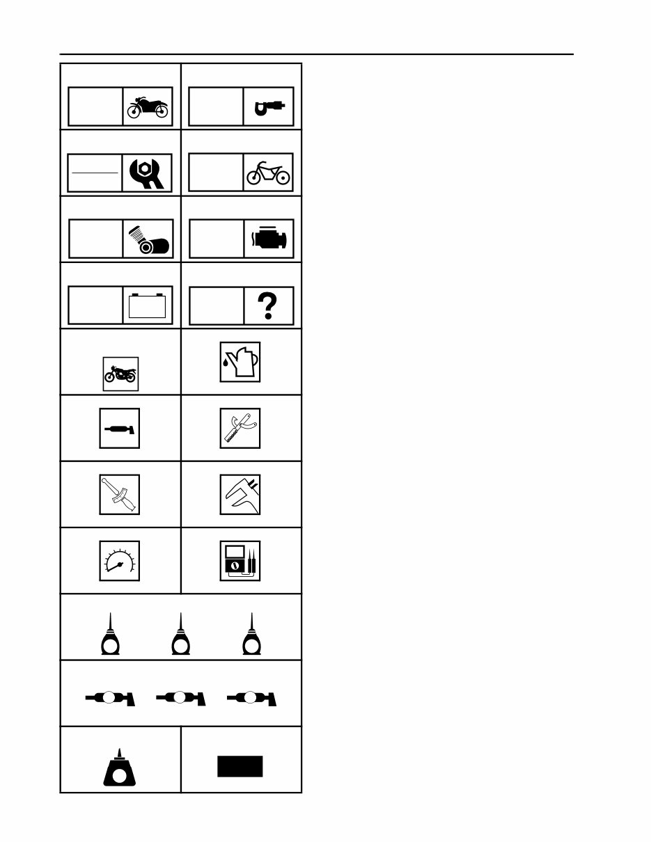
EAS00009 SYMBOLS The following symbols are not relevant to every vehicle. Symbols 1 to 8 indicate the subject of each chapter. 1 General information 2 Specifications 3 Periodic checks and adjustments 4 Chassis 5 Engine 6 Fuel injection system 7 Electrical system 8 Troubleshooting Symbols 9 to F indicate the following. 9 Serviceable with engine mounted 0 Filling fluid A Lubricant B Special tool C Tightening torque D Wear limit, clearance E Engine speed F Electrical data Symbols G to L in the exploded diagrams indicate the types of lubricants and lubrication points. G Engine oil H Gear oil I Molybdenum-disulfide oil J Wheel-bearing grease K Lithium-soap-based grease L Molybdenum-disulfide grease Symbols M to N in the exploded diagrams indicate the following. M Apply locking agent (LOCTITE ® ) N Replace the part 1 2 3 4 5 6 7 8 9 0 A B C D E F G H I J K L M N GEN INFO SPEC CHK ADJ CHAS ENG FI – + ELEC TRBL SHTG T R . . E G M B LS M LT New
CONTENTS SPECIFICATIONS ........................................................................................... 1 GENERAL SPECIFICATIONS ................................................................. 1 ENGINE SPECIFICATIONS .................................................................... 1 CHASSIS SPECIFICATIONS ................................................................... 1 ELECTRICAL SPECIFICATIONS ............................................................ 2 TIGHTENING TORQUES ......................................................................... 2 CHASSIS TIGHTENING TORQUES .................................................... 2 CABLE ROUTING .................................................................................... 3 PERIODIC CHECKS AND ADJUSTMENTS ................................................. 11 INTRODUCTION .................................................................................... 11 PERIODIC MAINTENANCE CHART FOR THE EMISSION CONTROL SYSTEM ................................................ 11 GENERAL MAINTENANCE AND LUBRICATION CHART .................... 12 CHASSIS ................................................................................................ 14 ADJUSTING THE REAR SHOCK ABSORBER ASSEMBLY ............. 14 CHASSIS ....................................................................................................... 16 FRONT AND REAR BRAKES ................................................................ 16 REAR BRAKE MASTER CYLINDER ................................................. 16 REAR SHOCK ABSORBER AND SWINGARM ..................................... 18 ENGINE .......................................................................................................... 22 ROCKER ARMS, PUSH RODS AND VALVE LIFTERS ....................... 22 GENERATOR AND STARTER CLUTCH ............................................... 24 STATOR COIL ASSEMBLY ............................................................... 24
– 1 – SPEC SPECIFICATIONS GENERAL SPECIFICATIONS ENGINE SPECIFICATIONS CHASSIS SPECIFICATIONS Item Standard Limit Model code 5PX4 (USA) 5PX5 (California) 5PX6 (CDN) ---- ---- ---- Item Standard Limit Electronic fuel injection Model (manufacturer) INP-732 (NIPPON INJECTOR) ---- Quantity 2 ---- Crankshaft Width A 132.8 ~ 133.2 mm (5.228 ~ 5.244 in) ---- Max. runout C ---- 0.04 mm (0.0016 in) Big end side clearance D 0.320 ~ 0.474 mm (0.0126 ~ 0.0187 in) ---- Big end radial clearance E 0.037 ~ 0.074 mm (0.0015 ~ 0.0029 in) 0.09 mm (0.0035 in) Crankshaft journal-to-crankshaft- journal bearing clearance 0.032 ~ 0.062 mm (0.0012 ~ 0.0024 in) 0.1 mm (0.0039 in) Fuel pump Pump type Electrical ---- Model (manufacturer) 5PX (MITSUBISHI) ---- Max. consumption amperage 5 A ---- Output pressure 392 ~ 588 kPa (3.92 ~ 5.88 kg/cm 2 , 55.7 ~ 83.6 psi) ---- Item Standard Limit Front tire Tire type Tubeless ---- Size 120/70 ZR 18 M/C (59 W) 120/70 ZR 18 (59 W) ---- Model (manufacturer) D220F ST G (DUNLOP)/ BT020F G (BRIDGESTONE) ---- A D C C E GENERAL SPECIFICATIONS/ ENGINE SPECIFICATIONS/CHASSIS SPECIFICATIONS
– 2 – SPEC ELECTRICAL SPECIFICATIONS TIGHTENING TORQUES CHASSIS TIGHTENING TORQUES Tire pressure (cold) 0 ~ 90 kg (0 ~ 198 lb) 250 kPa (2.5 kgf/cm 2 , 36 psi) ---- 90 kg (198 lb) ~ Maximum load* 250 kPa (2.5 kgf/cm 2 , 36 psi) ---- High-speed riding 250 kPa (2.5 kgf/cm 2 , 36 psi) ---- * Load is the total weight of the cargo, rider, passenger and accessories. Min. tire tread depth ---- 1.0 mm (0.04 in) Rear tire Tire type Tubeless ---- Size 200/50 ZR 17 M/C (75 W) 200/50 ZR 17 (75 W) ---- Model (manufacturer) D220 ST (DUNLOP)/ BT020R (BRIDGESTONE) ---- Tire pressure (cold) 0 ~ 90 kg (0 ~ 198 lb) 250 kPa (2.5 kgf/cm 2 , 36 psi) ---- 90 kg (198 lb) ~ Maximum load* 290 kPa (2.9 kgf/cm 2 , 42 psi) ---- High-speed riding 250 kPa (2.5 kgf/cm 2 , 36 psi) ---- * Load is the total weight of the cargo, rider, passenger and accessories. Min. tire tread depth ---- 1.0 mm (0.04 in) Item Standard Limit Ignition coils Model (manufacturer) J0447 (DENSO) ---- Minimum ignition spark gap 6 mm (0.24 in) ---- Primary coil resistance 1.32 ~ 1.78 Ω ---- Secondary coil resistance 12 ~ 18 kΩ ---- Charging system System type AC magneto ---- Model (manufacturer) F5PX (YAMAHA) ---- Nominal output 14 V/31 A at 5,000 r/min ---- Stator coil resistance/color 0.13 ~ 0.19 Ω/W–W ---- Item Thread size Tightening torque Remarks Nm m·kg ft·lb Rider footrest bracket and frame M10 48 4.8 35 LT Rear fender and turn signal light bracket (upper) M6 7 0.7 5.1 Rear fender and turn signal light bracket (lower) M6 9 0.9 6.5 Canister and rider footrest bracket (For California only) M6 9 0.9 6.5 Item Standard Limit CHASSIS SPECIFICATIONS/ ELECTRICAL SPECIFICATIONS/TIGHTENING TORQUES
– 3 – SPEC EB206000 CABLE ROUTING 1 Brake hose 2 Clutch cable 3 Rectifier/regulator 4 Rectifier/regulator lead 5 Rear brake light switch lead 6 Horn lead 7 Stator coil assembly lead È Fasten the rectifier/regulator lead, horn lead, and rear brake light switch lead with a plastic locking tie to the frame. É Fasten the stator coil assem- bly lead and rectifier/regulator lead with a plastic clamp. Ê Fasten the rear brake light switch lead, horn lead, and stator coil assembly lead with a plastic locking tie to the frame. Ë Fasten the stator coil assem- bly lead, horn lead, and rear brake light switch lead with a plastic locking tie to the frame. 2 1 3 4 5 6 7 1 1 Ë Ê É È CABLE ROUTING
– 4 – SPEC 1 Tachometer couplers 2 Right handlebar switch coupler and speedome- ter couplers 3 Main switch coupler 4 Left handlebar switch couplers 5 Left and right turn signal/position light connec- tors È Secure the wire harness in the holder at the white tape on the harness. É Route each lead behind the headlight assembly bracket bolts. A A 2 1 5 4 3 É É È CABLE ROUTING
This repair manual provides detailed instructions and step-by-step diagrams for various workshop procedures, including re-wiring, engine rebuilding, electrical diagrams, service procedures, and fluid capacities. It covers a wide range of topics such as:
General Information
Lubrication
Inspection and Adjustment
Fuel System
Engine Removal/Installation
Cylinder Head/Valve
Cylinder/Piston
Clutch
Gearshift Linkage
Sub transmission
Crankcase
Transmission
Crankshaft/Primary shaft
Front Wheel/Suspension
Rear Wheel/Suspension
Hydraulic Brake
Battery/Charging System
Ignition System
Electric Starter
Switches
Technical Features
Troubleshooting
And Much More
You can easily print specific pages or the entire manual, or view it directly on your screen. The manual is available in English and is compatible with both PC and MAC. It allows zooming in and out for detailed viewing. Upon payment, you will receive an email with a link for instant access, making it fast, easy, and secure. This make, model, and year-specific manual is suitable for professional mechanics and DIY enthusiasts alike.
For instant access, simply click on the "Instant Access" button and get the manual today.
Recently Viewed
5,521,897Happy Clients
2,594,462eManuals
1,120,453Trusted Sellers
15Years in Business
Price:
Actual Price:
2002-2005 Yamaha XV1700 Road Star Warrior Service & Repair Manual