EAS00003 NOTICE This manual was produced by the Yamaha Motor Company, Ltd. primarily for use by Yamaha deal- ers and their qualified mechanics. It is not possible to include all the knowledge of a mechanic in one manual. Therefore, anyone who uses this book to perform maintenance and repairs on Yamaha vehicles should have a basic understanding of mechanics and the techniques to repair these types of vehicles. Repair and maintenance work attempted by anyone without this knowledge is likely to render the vehicle unsafe and unfit for use. This model has been designed and manufactured to perform within certain specifications in regard to performance and emissions. Proper service with the correct tools is necessary to ensure that the vehicle will operate as designed. If there is any question about a service procedure, it is imperative that you contact a Yamaha dealer for any service information changes that apply to this model. This policy is intended to provide the customer with the most satisfaction from his vehicle and to conform to federal environmental quality objectives. Yamaha Motor Company, Ltd. is continually striving to improve all of its models. Modifications and significant changes in specifications or procedures will be forwarded to all authorized Yamaha deal- ers and will appear in future editions of this manual where applicable. NOTE: _ Designs and specifications are subject to change without notice. EAS00004 IMPORTANT MANUAL INFORMATION Particularly important information is distinguished in this manual by the following. The Safety Alert Symbol means ATTENTION! BECOME ALERT! YOUR SAFETY IS INVOLVED! Failure to follow WARNING instructions could result in severe injury or death to the motorcycle operator, a bystander or a person checking or repairing the motorcycle. A CAUTION indicates special precautions that must be taken to avoid dam- age to the motorcycle. A NOTE provides key information to make procedures easier or clearer. WARNING CAUTION: NOTE:
EAS00007 HOW TO USE THIS MANUAL This manual is intended as a handy, easy-to-read reference book for the mechanic. Comprehensive explanations of all installation, removal, disassembly, assembly, repair and check procedures are laid out with the individual steps in sequential order. 1 The manual is divided into chapters. An abbreviation and symbol in the upper right corner of each page indicate the current chapter. Refer to “SYMBOLS”. 2 Each chapter is divided into sections. The current section title is shown at the top of each page, except in Chapter 3 (“PERIODIC CHECKS AND ADJUSTMENTS”), where the sub-section title(s) appears. 3 Sub-section titles appear in smaller print than the section title. 4 To help identify parts and clarify procedure steps, there are exploded diagrams at the start of each removal and disassembly section. 5 Numbers are given in the order of the jobs in the exploded diagram. A circled number indicates a disassembly step. 6 Symbols indicate parts to be lubricated or replaced. Refer to “SYMBOLS”. 7 A job instruction chart accompanies the exploded diagram, providing the order of jobs, names of parts, notes in jobs, etc. 8 Jobs requiring more information (such as special tools and technical data) are described sequen- tially.
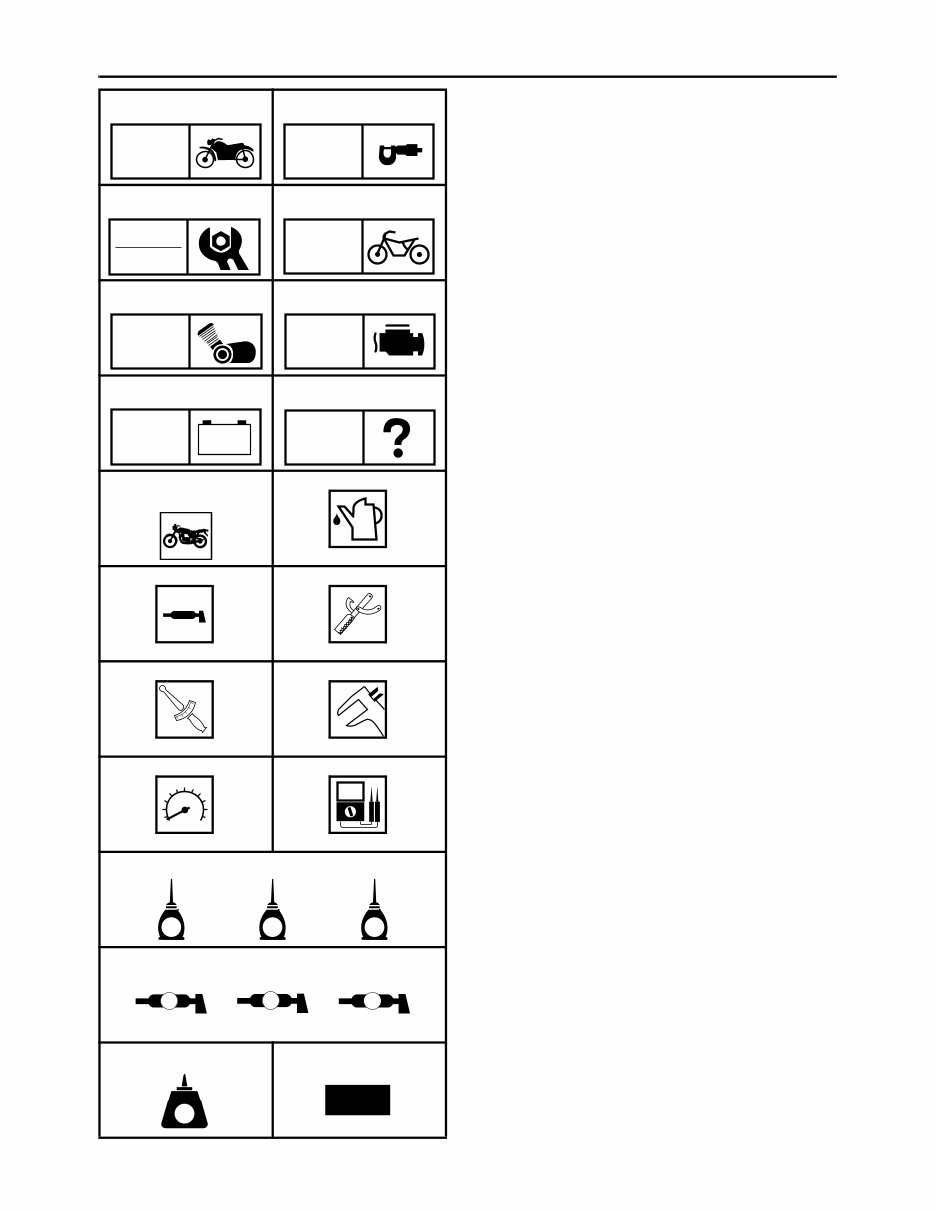
EAS00009 SYMBOLS The following symbols are not relevant to every vehicle. Symbols 1 to 8 indicate the subject of each chapter. 1 General information 2 Specifications 3 Periodic checks and adjustments 4 Chassis 5 Engine 6 Fuel injection system 7 Electrical system 8 Troubleshooting Symbols 9 to F indicate the following. 9 Serviceable with engine mounted 0 Filling fluid A Lubricant B Special tool C Tightening torque D Wear limit, clearance E Engine speed F Electrical data Symbols G to L in the exploded diagrams indicate the types of lubricants and lubrication points. G Engine oil H Gear oil I Molybdenum-disulfide oil J Wheel-bearing grease K Lithium-soap-based grease L Molybdenum-disulfide grease Symbols M to N in the exploded diagrams indicate the following. M Apply locking agent (LOCTITE ® ) N Replace the part 1 2 3 4 5 6 7 8 9 0 A B C D E F G H I J K L M N GEN INFO SPEC CHK ADJ CHAS ENG FI – + ELEC TRBL SHTG T R . . E G M B LS M LT New
CONTENTS SPECIFICATIONS .............................................................................................. 1 GENERAL SPECIFICATIONS ..................................................................... 1 ENGINE SPECIFICATIONS ........................................................................ 1 CHASSIS SPECIFICATIONS ....................................................................... 4 ELECTRICAL SPECIFICATIONS ................................................................ 4 TIGHTENING TORQUES............................................................................. 5 ENGINE TIGHTENING TORQUES ....................................................... 5 CHASSIS TIGHTENING TORQUES ..................................................... 6 LUBRICATION POINTS AND LUBRICANT TYPES .................................... 6 ENGINE ................................................................................................ 6 CABLE ROUTING ........................................................................................ 7 PERIODIC CHECKS AND ADJUSTMENTS .................................................... 18 INTRODUCTION ........................................................................................ 18 PERIODIC MAINTENANCE CHART FOR THE EMISSION CONTROL SYSTEM .................................................................................................... 18 GENERAL MAINTENANCE AND LUBRICATION CHART ........................ 19 SEAT AND SIDE COVERS ........................................................................ 21 FUEL TANK ................................................................................................ 22 INSTALLING THE FUEL HOSE JOINT 2 ............................................ 23 CHASSIS .......................................................................................................... 24 FRONT WHEEL AND BRAKE DISCS........................................................ 24 FRONT AND REAR BRAKES .................................................................... 26 FRONT BRAKE PADS......................................................................... 26 FRONT BRAKE CALIPERS ................................................................. 27 ASSEMBLING AND INSTALLING THE FRONT BRAKE CALIPERS .......................................................................................... 29 FRONT FORK ............................................................................................ 32 DRIVE BELT AND DRIVE PULLEY ........................................................... 33 INSTALLING THE DRIVE BELT AND DRIVE PULLEY....................... 35 ENGINE ............................................................................................................ 36 ENGINE ...................................................................................................... 36 TRANSFER GEAR CASE .......................................................................... 41 INSTALLING THE TRANSFER GEAR CASE...................................... 43 CRANKCASE ............................................................................................. 45 INSTALLING THE BEARING RETAINER............................................ 46 TRANSMISSION ........................................................................................ 47 XV17PCV(C)/XV17PCMV(C) 2006 WIRING DIAGRAM
– 1 – SPEC SPECIFICATIONS GENERAL SPECIFICATIONS ENGINE SPECIFICATIONS Item Standard Limit Model code 2D84 (XV17PCMV for USA) 2D85 (XV17PCMV(C) for California) 5PXG (XV17PCV for USA) 5PXH (XV17PCV(C) for California) ---- ---- ---- ---- Item Standard Limit Engine oil Lubrication system Dry sump ---- Recommended oil Yamalube 4 (20W40) or SAE 20W40 type ---- Recommended engine oil grade API service SE, SF, SG type or higher ---- Quantity Total amount 5.0 L (4.40 Imp qt, 5.29 US qt) ---- Engine 2.0 L (1.76 Imp qt, 2.11 US qt) ---- Oil tank 3.0 L (2.64 Imp qt, 3.17 US qt) ---- Without oil filter cartridge replace- ment 3.7 L (3.26 Imp qt, 3.91 US qt) ---- With oil filter cartridge replacement 4.1 L (3.61 Imp qt, 4.33 US qt) ---- Oil pressure (hot) 60 kPa (0.6 kg/cm 2 , 8.5 psi) at 900 r/min ---- Relief valve opening pressure 600 kPa (6.0 kg/cm 2 , 85 psi) ---- Oil temperature 70 ~ 90 °C (158 ~ 194 °F) ---- Valve lifters Valve lifter outside diameter 22.9620 ~ 22.9744 mm (0.9040 ~ 0.9045 in) ---- Valve lifter case inside diameter 23.000 ~ 23.021 mm (0.9055 ~ 0.9063 in) ---- Valve lifter-to-valve lifter case clear- ance 0.0256 ~ 0.0590 mm (0.0010 ~ 0.0023 in) ---- Pistons Piston-to-cylinder clearance 0.025 ~ 0.050 mm (0.001 ~ 0.002 in) 0.15 mm (0.006 in) Diameter D 96.960 ~ 96.975 mm (3.8173 ~ 3.8179 in) ---- Height H 10 mm (0.39 in) ---- H D GENERAL SPECIFICATIONS/ ENGINE SPECIFICATIONS
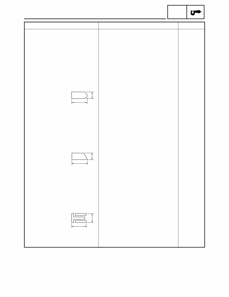
– 2 – SPEC ENGINE SPECIFICATIONS Piston pin bore (in the piston) Diameter 22.004 ~ 22.015 mm (0.8663 ~ 0.8667 in) 22.045 mm (0.8679 in) Offset 1.0 mm (0.0394 in) ---- Piston pins Outside diameter 21.991 ~ 22.000 mm (0.8658 ~ 0.8661 in) 21.971 mm (0.8650 in) Piston pin-to-piston pin bore clear- ance 0.004 ~ 0.024 mm (0.00016 ~ 0.00094 in) 0.074 mm (0.0029 in) Piston rings Top ring Ring type Barrel ---- Dimensions (B × T) 1.2 × 3.8 mm (0.047 × 0.150 in) ---- End gap (installed) 0.30 ~ 0.45 mm (0.012 ~ 0.018 in) 0.65 mm (0.026 in) Ring side clearance 0.03 ~ 0.08 mm (0.0012 ~ 0.0031 in) 0.12 mm (0.0047 in) Plating/coating Chrome plated/parkerizing ---- 2nd ring Ring type Taper ---- Dimensions (B × T) 1.2 × 3.8 mm (0.047 × 0.150 in) ---- End gap (installed) 0.30 ~ 0.45 mm (0.012 ~ 0.018 in) 0.8 mm (0.031 in) Ring side clearance 0.03 ~ 0.07 mm (0.0012 ~ 0.0028 in) 0.12 mm (0.0047 in) Plating/coating Parkerizing ---- Oil ring Dimensions (B × T) 2.5 × 3.4 mm (0.098 × 0.134 in) ---- End gap (installed) 0.2 ~ 0.7 mm (0.008 ~ 0.028 in) ---- Plating/coating Chrome plated/parkerizing ---- Item Standard Limit T B B T B T
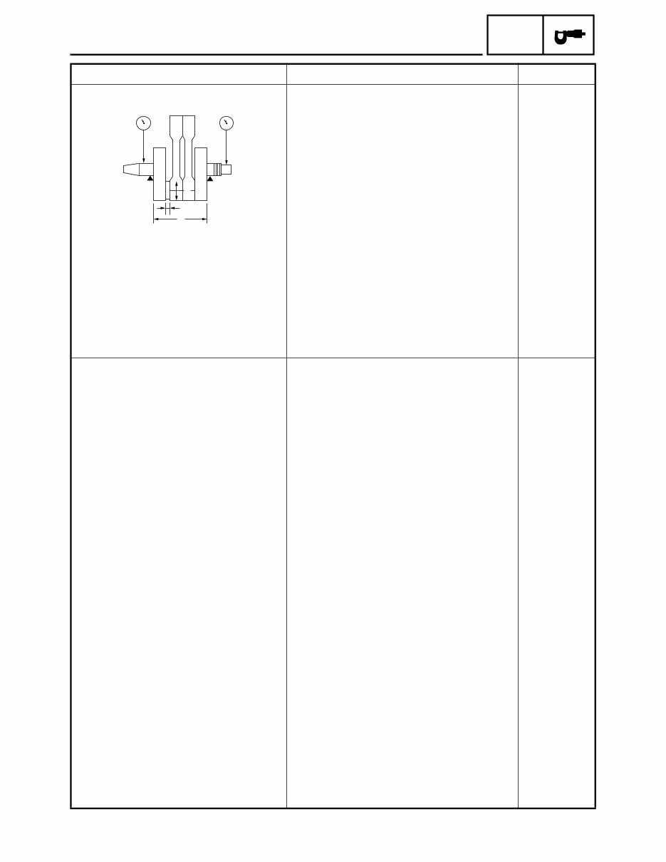
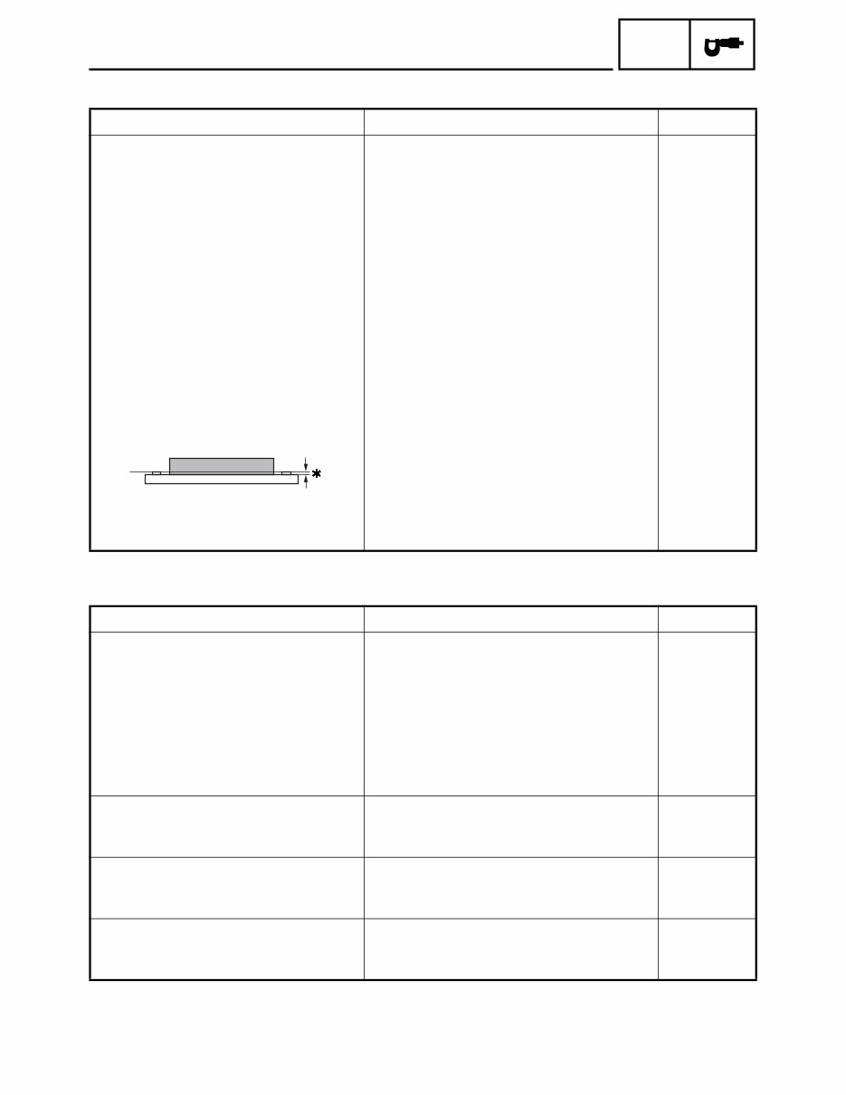
– 3 – SPEC ENGINE SPECIFICATIONS Crankshaft Width A 105.8 ~ 106.2 mm (4.165 ~ 4.181 in) ---- Max. runout C ---- 0.04 mm (0.0016 in) Big end side clearance D 0.320 ~ 0.474 mm (0.0126 ~ 0.0187 in) ---- Big end radial clearance E 0.037 ~ 0.074 mm (0.0015 ~ 0.0029 in) 0.09 mm (0.0035 in) Crankshaft-journal-to-crankshaft- journal-bearing clearance 0.030 ~ 0.062 mm (0.0012 ~ 0.0024 in) 0.1 mm (0.0039 in) Clutch Clutch type Wet, multiple disc ---- Clutch release method Outer pull, rack and pinion (pull rod type) ---- Clutch release method operation Cable operation ---- Operation Left-hand operation ---- Clutch cable free play (at the end of the clutch lever) 10 ~ 15 mm (0.39 ~ 0.59 in) ---- Friction plates Thickness 2.9 ~ 3.1 mm (0.114 ~ 0.122 in) 2.8 mm (0.110 in) Plate quantity 9 ---- Clutch plates Thickness 2.2 ~ 2.4 mm (0.087 ~ 0.094 in) ---- Plate quantity 8 ---- Max. warpage ---- 0.2 mm (0.008 in) Clutch springs Free length 7 mm (0.276 in) ---- Spring quantity 1 ---- Min. length ---- 6.5 mm (0.256 in) Clutch housing thrust clearance 0.10 ~ 0.37 mm (0.0039 ~ 0.0146 in) ---- Clutch housing radial clearance 0.017 ~ 0.053 mm (0.0007 ~ 0.0021 in) ---- Primary reduction gear backlash tol- erance A-A, B-B, C-C, D-D, E-E ---- Primary drive gear backlash number A, B, C, D, E ---- Primary driven gear backlash num- ber A, B, C, D, E ---- Item Standard Limit A D C C E
– 4 – SPEC CHASSIS SPECIFICATIONS/ ELECTRICAL SPECIFICATIONS CHASSIS SPECIFICATIONS ELECTRICAL SPECIFICATIONS Item Standard Limit Rear brake Brake type Single-disc brake ---- Operation Right-foot operation ---- Brake pedal free play 0 mm (0 in) ---- Brake pedal position (from the top of the rider footrest to the top of the brake pedal) 86 mm (3.4 in) ---- Recommended fluid DOT 4 ---- Brake discs Diameter × thickness 282 × 6 mm (11.10 × 0.24 in) ---- Min. thickness ---- 5.5 mm (0.22 in) Max. deflection ---- 0.15 mm (0.006 in) Brake pad lining thickness 5.8 mm (0.23 in) 0.8 mm (0.03 in) Master cylinder inside diameter 12.7 mm (0.5 in) ---- Caliper cylinder inside diameter 41.3 mm (1.63 in) ---- Item Standard Limit Bulbs (voltage/wattage × quantity) Headlight 12 V 60 W/55 W × 1 ---- Licence plate light 12 V 3.8 W × 2 ---- Tail/brake light LED ---- Front turn signal/position light 12 V 23 W/8 W × 2 ---- Rear turn signal light 12 V 21 W × 2 ---- Speedometer light LED × 1 ---- Tachometer light LED × 1 ---- Starting circuit cut-off relay Model/manufacturer G8R-30Y-U3/OMRON ---- Coil resistance 162 ~ 198 Ω ---- Fuel injection system relay Model/manufacturer G8R-30Y-U3/OMRON ---- Coil resistance 162 ~ 198 Ω ---- Throttle position sensor Resistance 4 ~ 6 kΩ/L-B ---- Output voltage (at idle) 0.63 ~ 0.73 V ----
Thank you for considering this comprehensive Workshop Service Repair Manual for the Yamaha XV1700 Road Star Warrior Midnight Silverado 1700 Motorcycle from 2006 to 2010.
This manual is an invaluable resource for both professional mechanics and DIY enthusiasts, covering every service and repair procedure with easy-to-follow step-by-step instructions and detailed pictures.
By utilizing this manual, you can significantly reduce repair costs by performing the maintenance and repairs yourself. The manual is yours to keep forever, allowing you to print out specific pages, chapters, or the entire manual. Additionally, it can be conveniently accessed on your tablet or smartphone.
All models, engines, trim, and transmission types are comprehensively covered in this high-quality Service Repair Workshop Manual, encompassing all repair procedures from A to Z.
Compatible with all PC and MAC computers, tablets, and mobile phones, this downloadable manual requires only Adobe Reader, which is typically pre-installed on most computers or can be downloaded for free.
Upon payment via Visa, MasterCard, or PayPal, the manual will be instantly emailed to the address provided during checkout, ensuring prompt access to the essential information it contains.
Rest assured, customer satisfaction is guaranteed with this Workshop Service Repair Manual.
Recently Viewed
5,521,897Happy Clients
2,594,462eManuals
1,120,453Trusted Sellers
15Years in Business
Price:
Actual Price:
2006-2009 Yamaha XV1700 Road Star Warrior Midnight Silverado 1700 Motorcycle Service & Repair Manual 2 by