



SERVICE MANUAL
2008
11D-F8197-E0
XT660Z

XT660Z (2008)
SERVICE MANUAL
© 2008 by Yamaha Motor Italia S.p.A.
First edition, May 2008
All rights reserved. Any reproduction or
unauthorized use without the written
permission of Yamaha Motor Italia S.p.A.
is expressly prohibited.
Printed in Italy

EAS00020
NOTICE
This manual was produced by the Yamaha Motor Italia S.p.A. primarily for use by Yamaha dealers and
their qualified mechanics. It is not possible to include all the knowledge of a mechanic in one manu-
al.Therefore, anyone who uses this book to perform maintenance and repairs on Yamaha vehicles
should have a basic understanding of mechanics and the techniques to repair these types of vehi-
cles. Repair and maintenance work attempted by anyone without this knowledge is likely to render
the vehicle unsafe and unfit for use.
Yamaha Motor Italia S.p.A. is continually striving to improve all of its models. Modifications and sig-
nificant changes in specifications or procedures will be forwarded to all authorized Yamaha dealers
and will appear in future editions of this manual where applicable.
NOTE:
Designs and specifications are subject to change without notice.
EAS00040
IMPORTANT MANUAL INFORMATION
Particularly important information is distinguished in this manual by the following.
The Safety Alert Symbol means ATTENTION! BECOME ALERT! YOUR SAFE-
TY IS INVOLVED!
Failure to follow WARNING instructions could result in se v ere injur y or death to
the motorcycle operator, a bystander or a person checking or repairing the mo-
torcycle.
A CAUTION indicates special precautions that must be taken to avoid damage
to the motorcycle.
NOTE: A NOTE provides key information to make procedures easier or clearer.
WARNING
CAUTION:
EAS20090
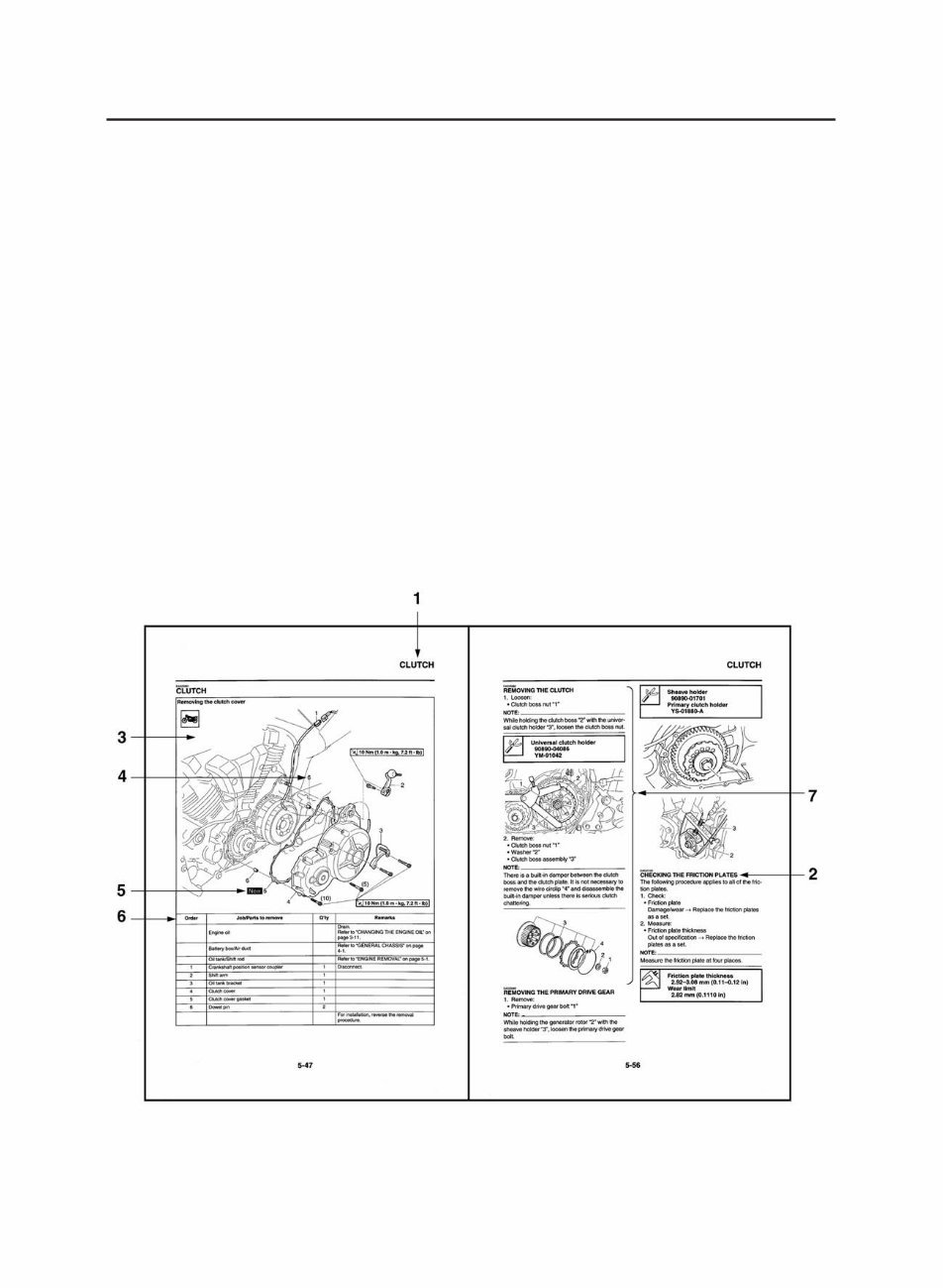
HOW TO USE THIS MANUAL
This manual is intended as a handy, easy-to-read reference book for the mechanic.Comprehensive
explanations of all installation, removal, disassembly, assembly, repair and check procedures are
laid out with the individual steps in sequential order.
• The manual is divided into chapters and each chapter is divided into sections. The current section
title “1” is shown at the top of each page.
• Sub-section titles “2” appear in smaller print than the section title.
• To help identify parts and clarify procedure steps, there are exploded diagrams “3” at the start of
each removal and disassembly section.
• Numbers “4” are given in the order of the jobs in the exploded diagram. A number indicates a dis-
assembly step.
• Symbols “5” indicate parts to be lubricated or replaced. Refer to “SYMBOLS”.
• A job instruction chart “6” accompanies the exploded diagram, providing the order of jobs, names
of parts, notes in jobs, etc.
• Jobs “7” requiring more information (such as special tools and technical data) are described
sequentially.
EAS20100
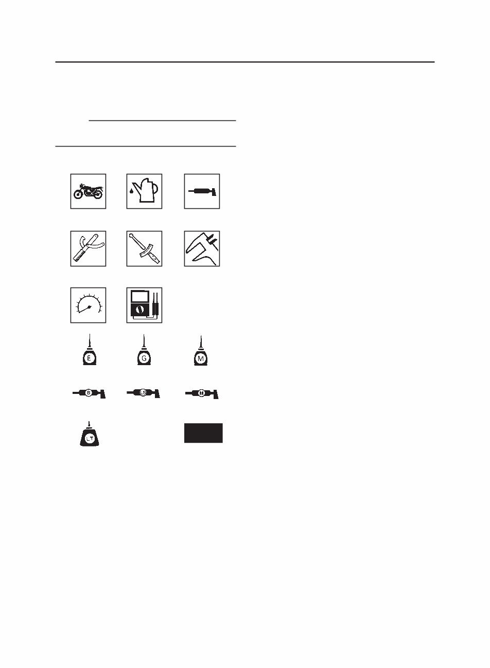
SYMBOLS
The following symbols are used in this manual
for easier understanding.
NOTE:
The following symbols are not relevant to every
vehicle.
1. Serviceable with engine mounted
2. Filling fluid
3. Lubricant
4. Special tool
5. Tightening torque
6. Wear limit, clearance
7. Engine speed
8. Electrical data
9. Engine oil
10. Gear oil
11. Molybdenum disulfide oil
12. Wheel bearing grease
13. Lithium-soap-based grease
14. Molybdenum disulfide grease
15. Apply locking agent (LOCTITE
®
)
16. Replace the part with a new one.
New
1 2 3
4 5
7 8
6
9 11 10
12 14 13
15 16
GENERAL INFORMATION
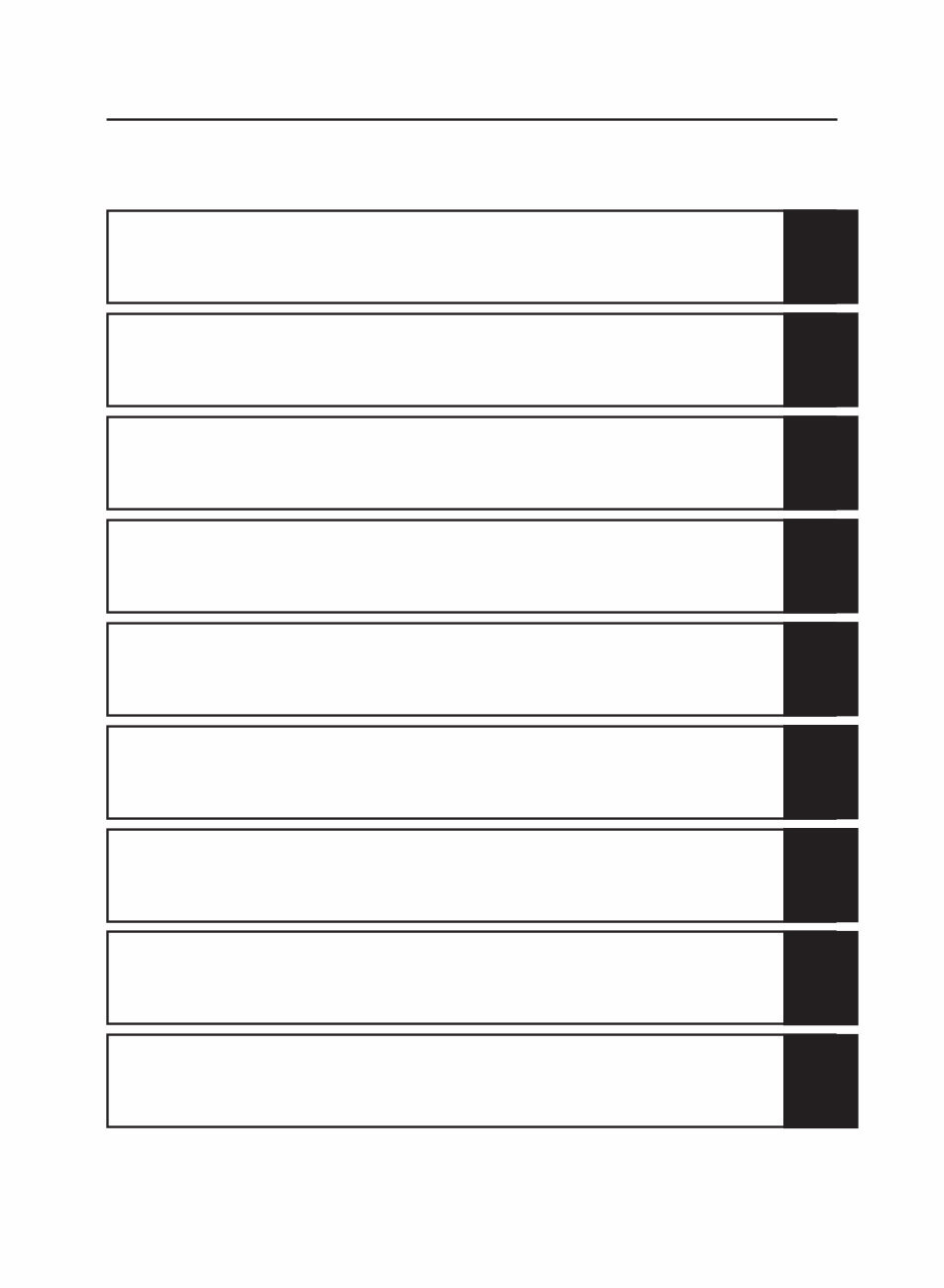
TABLE OF CONTENTS
1
SPECIFICATIONS
2
PERIODIC CHECKS AND
ADJUSTMENTS
3
CHASSIS
4
ENGINE
5
COOLING SYSTEM
6
FUEL INJECTION SYSTEM
7
ELECTRICAL SYSTEM
8
TROUBLESHOOTING
9

GENERAL INFORMATION
IDENTIFICATION............................................................................................ 1-1
VEHICLE IDENTIFICATION NUMBER..................................................... 1-1
MODEL LABEL ......................................................................................... 1-1
FEATURES ..................................................................................................... 1-2
OUTLINE OF THE FI SYSTEM ................................................................ 1-2
FI SYSTEM ............................................................................................... 1-3
INSTRUMENT FUNCTIONS .................................................................... 1-4
IMPORTANT INFORMATION ........................................................................ 1-7
PREPARATION FOR REMOVAL AND DISASSEMBLY ........................... 1-7
REPLACEMENT PARTS .......................................................................... 1-7
GASKETS, OIL SEALS AND O-RINGS ................................................... 1-7
LOCK WASHERS/PLATES AND COTTER PINS ..................................... 1-7
BEARINGS AND OIL SEALS ................................................................... 1-8
CIRCLIPS ................................................................................................. 1-8
CHECKING THE CONNECTIONS ................................................................ 1-9
SPECIAL TOOLS ...........................................................................................1-10
1

1-1
IDENTIFICATION
1
IDENTIFICATION
EAS00170
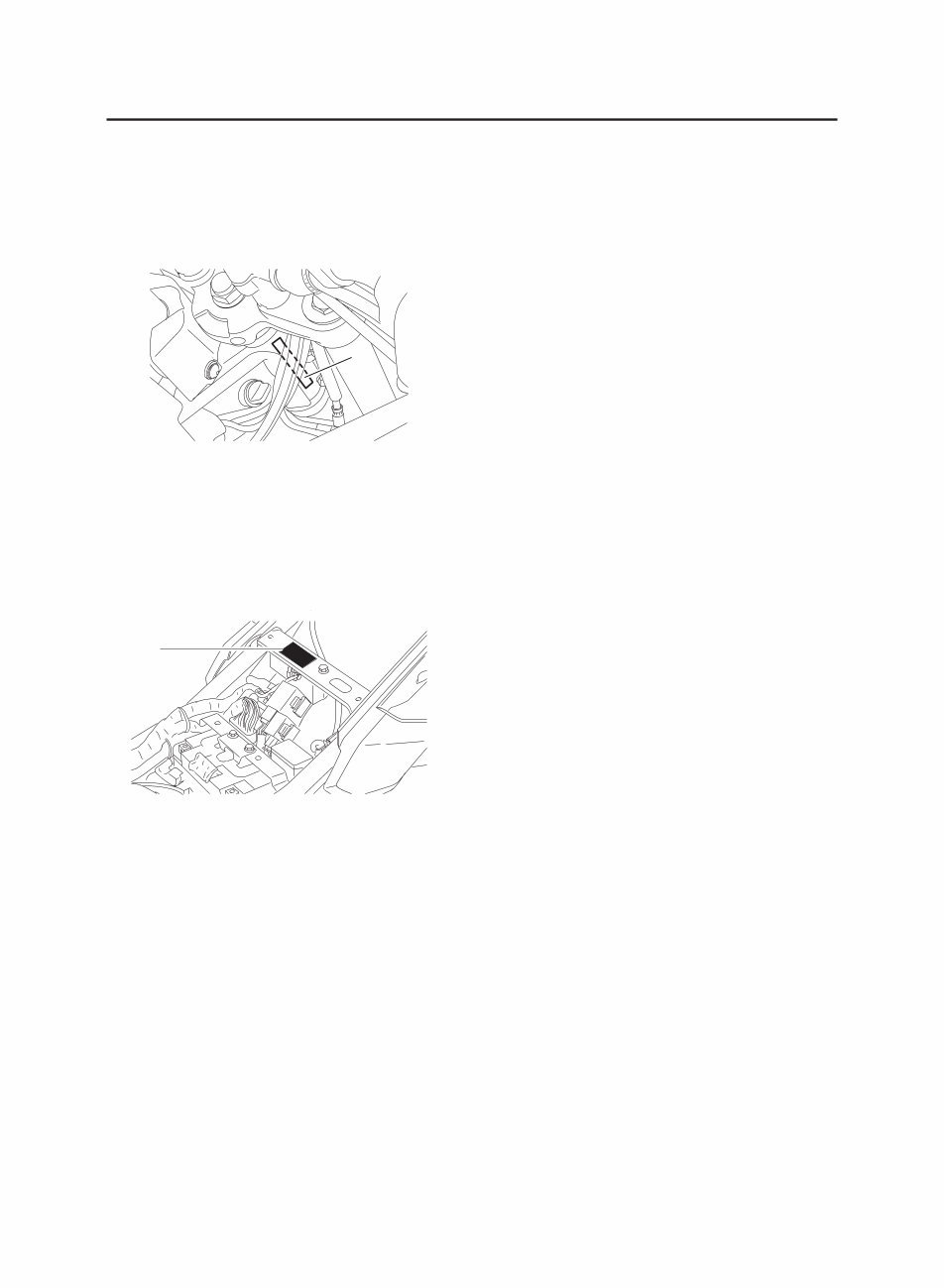
VEHICLE IDENTIFICATION NUMBER
The vehicle identification number “1” is stamped
into the right side of the steering head pipe.
EAS00180
MODEL LABEL
The model label “1” is affixed to the frame under
the seat. This information will be needed to or-
der spare parts.
1-2
FEATURES
EAS00019
FEATURES
EAS00896
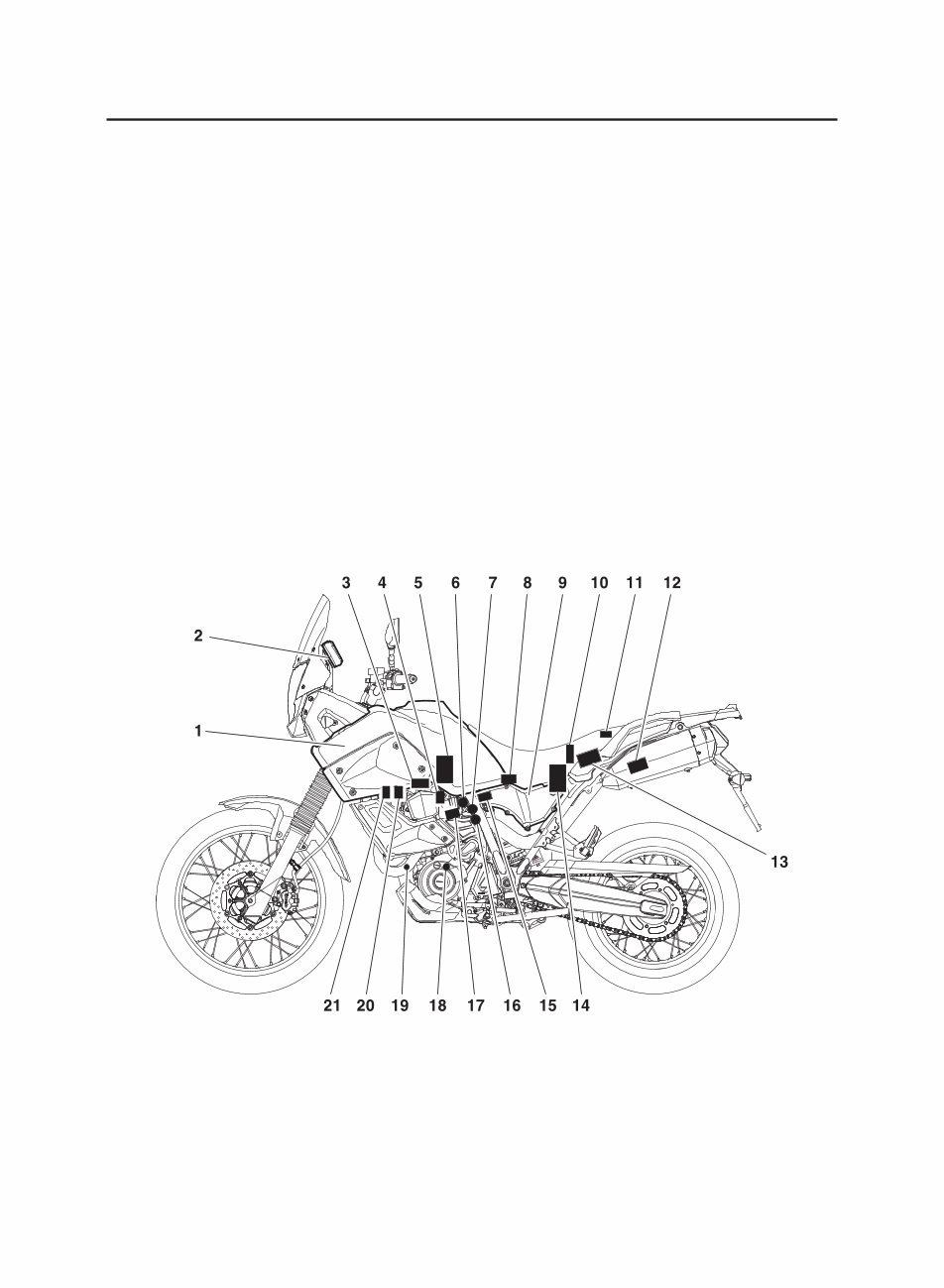
OUTLINE OF THE FI SYSTEM
The main function of a fuel supply system is to provide fuel to the combustion chamber at the opti-
mum air-fuel ratio in accordance with the engine operating conditions and the atmospheric temper-
ature. In a conventional carburetor system, the air-fuel ratio of the mixture that is supplied to the com-
bustion chamber is created by the volume of the intake air and the fuel that is metered by the jet used
in the respective chamber. Despite the same volume of intake air, the fuel volume requirement varies
with the engine operating conditions, such as acceleration, deceleration, or operation under a heavy
load. Carburetors that meter the fuel through the use of jets have been provided with various auxil-
iary devices, so that an optimum air-fuel ratio can be achieved to accommodate the constant changes
in the operating conditions of the engine. As the requirements for engines to deliver more perform-
ance and cleaner exhaust gases increase, it becomes necessary to control the air-fuel ratio in a more
precise and finely tuned manner.To accommodate this need, this model has adopted an electroni-
cally controlled fuel injection (FI) system in place of a conventional carburetor system. This system
can achieve an optimum air-fuel ratio required by the engine at all times by using a microprocessor
that regulates the fuel injection volume according to the engine operating conditions detected by var-
ious sensors. Adoption of the FI system has resulted in a highly precise fuel supply, improved engine
response, better fuel economy, and reduced exhaust emissions. Furthermore, the air induction sys-
tem (AI system) has been placed under computer control together with the FI system in order to re-
alize cleaner exhaust gases.
1. Fuel tank
2. Engine trouble warning light
3. Ignition coil
4. Spark plug
5. Fuel pump
6. Idling adjustment screw
7. Throttle position sensor
8. Intake air pressure sensor
9. Air filter case
10. ECU
11. Lean angle cut-off switch
12. Catalytic converter
13. Fuel injection system relay
14. Battery
15. Intake air temperature sensor
16. Coolant temperature sensor
17. Fuel injector
18. Crankshaft position sensor
19. O
2
sensor
20. Air induction system solenoid
21. Air cut-off valve
You're Reading a Preview
What's Included?
 Lifetime Access
Fast Download Speeds
Online & Offline Access
Access PDF Contents & Bookmarks
Full Search Facility
Print one or all pages of your manual
$32.99
2008 Yamaha XT660Z Tenere Workshop Repair manual
Viewed 27 Times Today

What's Included?
Lifetime Access
Fast Download Speeds
Online & Offline Access
Access PDF Contents & Bookmarks
Full Search Facility
Print one or all pages of your manual
$32.99

Secure transaction
What's Included?
Lifetime Access
Fast Download Speeds
Online & Offline Access
Access PDF Contents & Bookmarks
Full Search Facility
Print one or all pages of your manual
Description
Get a better understanding of your 2008 Yamaha XT660Z Tenere with the Workshop Repair manual. This professional manual contains comprehensive instructions and high-quality procedures to help you fix car problems, saving you time and aiding in decision-making.
- General information
- Specifications
- Periodic checks and adjustment
- Chassis
- Engine
- Cooling system
- Fuel injection system
- Electrical system
- Troubleshooting
The manual is available in PDF format, compatible with all versions of Windows and Mac. It is in English and requires Adobe Reader. Whether you're a professional mechanic or a DIY enthusiast, this manual will keep you up-to-date and enhance your knowledge, making it a useful resource for maintaining your car.


