NOTICE This manual was written by Yamaha Motor Company Ltd. primarily for use by Yamaha dealers and qualified mechanics. It is not possible to put an entire mechanic's education into one manu- al, so persons using this book to perform maintena,rice and repairs on Yamaha motorcycles should have a basic understanding of the mechanical concepts and procedures inherent in mo- torcycle repair technology. '{Vith?ut such knowledge, attempted repairs or service to the motor- cycle may render it unfit to 'U,se and/or unsafe. for USA, California This model has been designed and manufactured to perform within certain specifications in regard to performance and emissions. Proper service with the correct tools in neces- sary to ensure that the motorcycle will operate as designed. If there is any question about a service procedure, it is imperative that you contact a Yamaha dealer for any service in- formation changes that apply to this model. This policy is intended to provide the cus- tomer with the most satisfaction from his motorcycle and to conform with federal envi- ronmental quality objectives. Yamaha Motor Company, Ltd. is continually striving to improve all models manufactured by Yamaha. Modifications and significant changes in specifications or procedures will be forward- ed to all Authorized Yamaha dealers and will, where applicable, appear in future editions of this manual. NOTE=----------------------------------------------- FOR USA, California: This Service Manual contains information regarding periodic maintenance to the emission con- trol system. Please read this material carefullv PARTICULARLY IMPORTANT INFORMATION This material is distinguished by the following notation. A WARNING NOTE: The Safety Alert Symbol means ATTENTION! BECOME ALERT! YOUR SAFETY IS INVOLVED! Failure to follow WARNING instructions could result in severe injury or death to the motorcycle operato,r, a bystander, or a person inspecting or repairing the motorcycle. A CAUTION indicates special precautions that must be taken to avoid damage to the motorcycle. A NOTE provides key information to make procedures easier or clearer.
HOW TO USE THIS MANUAL CONSTRUCTION OF THIS MANUAL This manual consists of chapters for the main categories of subjects. (See "Illustrated symbols") 1st title CD: This is a chapter with its symbol on the upper right of each page. 2nd title®: This title appears on the upper of each page on the left of the chapter symbol. (For the chapter "Periodic inspection and adjustment" the 3rd title appears.) 3rd title@: This is a final title. MANUAL FORMAT All of the procedures in this manual are organized in a sequential, step-by-step format. The informa- tion has been compiled to provide the mechanic with an easy to read, handy reference that contains comprehensive explanations of all disassembly, repair, assembly, and inspections. A set of particularly important procedure@ is placed between a line of asterisks"*" with each proce- preceded by "e". IMPORTANT FEATURES • Data and a special tool are framed in a box preceded by a relevant symbol @. • An encircled numeral @ indicates a part name, and an encircled alphabetical letter data or an align- ment mark (j), the others being indicated by an alphabetical letter in a box @. • A condition of a faulty component will precede an arrow symbol and the course of action required the symbol ®. EXPLODED DIAGRAM Each chapter provides exploded diagrams before each disassembly section for ease in identifying cor- rect disassembly and assembly procedures. UHihaerankuHnoaraii"910ol z lt:l tool: iNSPecTION AND REPAIR •C.,bondepoei!f UHarounct.diCII!IIIr THac.reloaYoodlldii!IY!IinalhiiUO.,kplug tlvaada.DOR01UHash .. pinstrumem Avoodscr.-cchinalhe-..minum. .... -·-- -- .. •It= •At'-Ctlaatr"'-"",..... (i) -.de thick.,.· •MiheWifNCIIIiiiOiftofltiKificMion,re- aurt- rM cytlriiMt hNd. '----'----'= _______ .c.c.•RO.c.c.•c...rFO..:...•_• l , 1 ol ' I / _., •Driyecl\tin
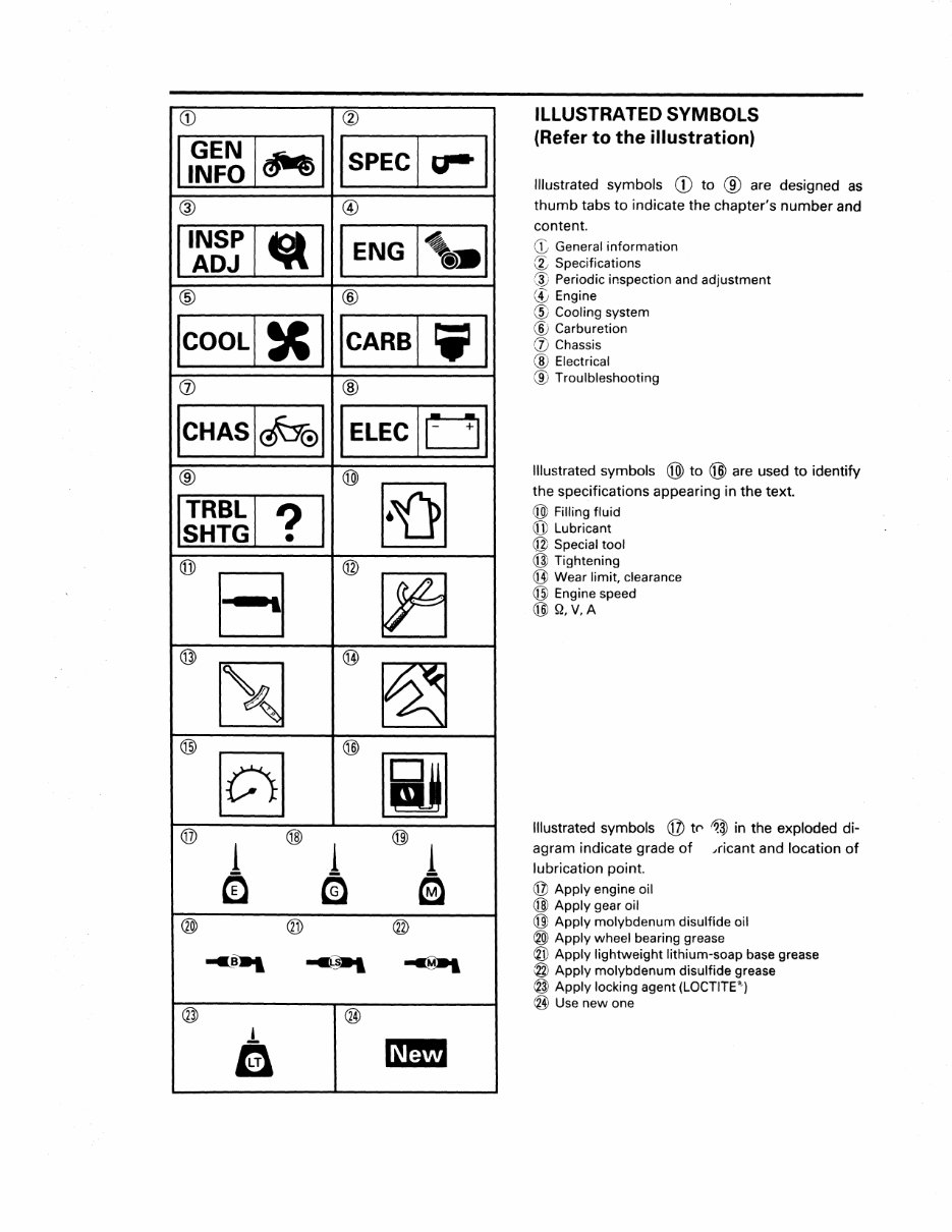
CD @ I SPEC I fr8' I ® @ ttt II ENG l'-1 ® @ icARsl i11 (j) ® IELEciUI ® ® ? I (j]) 8 @ @) @ @ [0] @ [ij] ® 1 @) 1 @) 1 cQ m a ® ® @ .. -. -«M»> @ ® l a ILLUSTRATED SYMBOLS (Refer to the illustration) Illustrated symbols CD to ® are designed as thumb tabs to indicate the chapter's number and content. ([., General information (g:, Specifications @ Periodic inspection and adjustment (!,. Engine @ Cooling system ® Carburetion (j) Chassis @ Electrical ® Troulbleshooting Illustrated symbols @ to @ are used to identify the specifications appearing in the text. @) Filling fluid @Lubricant @ Special tool @ Tightening (jJ) Wear limit, clearance @ Engine speed @J Q, V,A Illustrated symbols @ tf" in the exploded di- agram indicate grade of ,ricant and location of lubrication point. @ Apply engine oil @ Apply gear oil @l Apply molybdenum disulfide oil ® Apply wheel bearing grease @ Apply lightweight lithium-soap base grease @ Apply molybdenum disulfide grease @ Apply locking agent (LOCTITE") ®Use new one
CONTENTS GENERAL INFORMATION ....................................................................... 1 MOTORCYCLE IDENTIFICATION ............................................................... 1 VEHICLE IDENTIFICATION NUMBER .................................................. 1 ENGINE SERIAL NUMBER ................................................................... 1 SPECIFICATIONS ........................................................................................ 2 GENERAL SPECIFICATIONS .................· ..................................................... 2 MAINTENANCE SPECIFICATIONS ............................................................3 ENGINE .................................................................................................. 3 CHASSI$ ................................................................................................ 6 LUBRICATION POINTS AND LUBRICANT TYPE ......................................7 CHASSI$ ................................................................................................7 CABLE ROUTING ........................................................................................ 8 ENGINE ........................................................................................................ 12 ENGINE ASSEMBLY AND ADJUSTMENT .............................................. 12 CLUTCH AND OIL PUMP .................................................................... 12 CHASSIS ...................................................................................................... 13 FRONT FORK ............................................................................................. 13
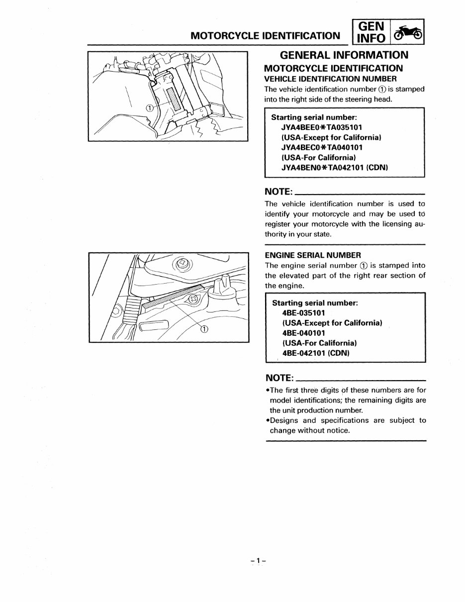
MOTORCYCLE IDENTIFICATION GENERAL INFORMATION MOTORCYCLE IDENTIFICATION VEHICLE IDENTIFICATION NUMBER The vehicle identification number CD is stamped into the right side of the steering head. Starting serial number: JYA4BEEO*TA035101 (USA-Except for California) JVA4BECO*TA040101 (USA-For California) JYA4BENO*TA042101 (CONI NOTE: __________________ ___ The vehicle identification number is used to identify your motorcycle and may be used td register your motorcycle with the licensing au- thority in your state. ENGINE SERIAL NUMBER The engine serial number CD is stamped into the elevated part of the right rear section of the engine. -1- Starting serial number: 4BE-035101 (USA-Except for California) 4BE-040101 (USA-For California) 4BE-042101 (CON) NOTE: __________________ __ •The first digits pf these are for model identifications; the remaining digits are the unit production number. •Designs and specifications are subject to change without notice.
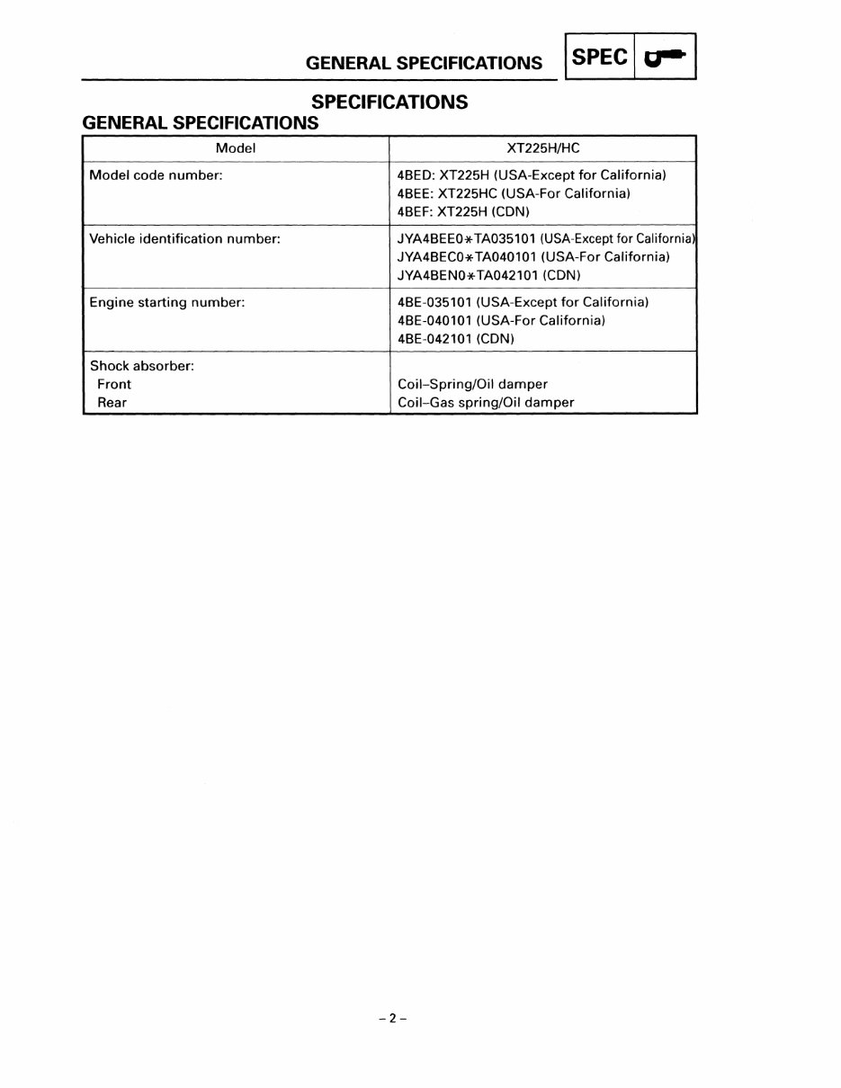
GENERAL SPECIFICATIONS I SPEC I g-1 SPECIFICATIONS GENERAL SPECIFICATIONS Model XT225H/HC Model code number: 4BEO: XT225H (USA-Except for California) 4BEE: XT225HC (USA-For California) 4BEF: XT225H (CON) Vehicle identification number: JYA4BEEO*TA035101 (USA-Except for California) JYA4BECO*TA040101 (USA-For California) JYA4BENO*TA042101 (CON) Engine starting number: 4BE-035101 (USA-Except for California) 4BE-040101 (USA-For California) 4BE-042101 (CON) Shock absorber: Front Coil-Spring/Oil damper Rear Coil-Gas spring/Oil damper -2-
MAINTENANCE SPECIFICATIONS I SPEC I u-1 MAINTENANCE SPECIFICATIONS ENGINE Model XT225H/HC Valve, valve seat, valve guide: Valve clearance (cold): Intake 0.05-0.09 mm (0.002-0.004 in) Exhaust 0.15-0.19 mm (0.006-0.007 in) Valve dimensions: Intake "A" head diameter 33.9-34.1 mm (1.33-1.34 in) "B" face width 2.26 mm (0.089 in) "C" seat width 0.9-1.1 mm (0.03-0.04 in) "D" margin thickness 0.8-1.2 mm (0.03-0.05 in) Exhaust "A" head diameter 28.4-28.6 mm (1.12-1.13 in) "B" face width 2.26 mm (0.089 in) "C" seat width 0.9-1.1 mm (0.03-0.04 in) "0" margin thickness 0.8-1.2 mm (0.031-0.050 in) USA California CON Carburetor: 1.0. Mark 4BE 10 4BE 00 3RW01 Main jet (M.J.) #130 #122.5 Main air jet size (M.A.J.) 1.0 0.9 Jet needle (J.N.) 5DL27-1 5GN50-3/5 Needle jet (N.J.) 0-1 Q-0 Pilot air jet size (P.A.J. 1) #60 #80 (P.A.J. 2) 1.2 1.2 Pilot jet (P.J.) #40 #42.5 Pilot outlet (P.O.) 0.85 Bypass 1 (B.P.1) 0.8 Pilot screw (P.S.) Preset 2 turns out Valve seat size (V.S.) 2.0 Starter jet (G.S.1) #60 #45 (G.S.2) 0.7 Fuel level (with special tool) (F.L.) 11.0-12.0 mm (0.43-0.47 in) Below from the float chamber mating surface (front) Float height (F. H.) 14.1-15.1 mm (0.56-0.59 in) Below from the float chamber mating surface (front) Engine idle speed 1,300-1,500 r/min Intake vacuum 220-240 mmHg -3-
Get your hands on the comprehensive 1992-2000 Yamaha XT225 SEROW Service Manual, including the Repair Manual, Shop Manual, Workshop Guide, and Owners Manual. This manual is a must-have for anyone working on a 1992-2000 Yamaha XT225 SEROW, whether you're a professional mechanic or a DIY enthusiast.
Includes detailed procedures with pictures
Exploded parts diagrams
Troubleshooting and electrical guidance
Covers engine rebuild, valve jobs, transmission, suspension, and more
Provides complete servicing from wheel to wheel
Rest assured, the 1992-2000 Yamaha XT225 SEROW Service Manual is guaranteed to match your specific motorcycle's model and year. Supplementary manuals required to cover all the model years listed are also included in the listings. Additionally, you'll receive the printable 1992-2000 Yamaha XT225 SEROW User Guide and Maintenance Manual, featuring standard maintenance procedures, adjustments, schedules, control functions, specifications, and operating instructions.
These manuals have been meticulously restored and are invaluable resources, especially if you're working on a classic bike or aiming to enhance customer satisfaction. The printable 1992-2000 Yamaha XT225 SEROW Repair Manual is bookmarked and keyword searchable, ensuring ease of use and top-notch quality. This is the right manual for the right job, right away.
Don't miss out on this exceptional ATV Service Manual for the 1992-2000 Yamaha XT225 SEROW. Purchase your Repair Manual today and elevate your repair experience. Thank you for choosing us!
Recently Viewed
5,521,897Happy Clients
2,594,462eManuals
1,120,453Trusted Sellers
15Years in Business
Price:
Actual Price:
1992-2000 Yamaha XT225 SEROW Service Manual Repair Manuals -and- Owner's Manual, Ultimate Set