

2005-2011 Yamaha Xt125r Xt125x Service & Repair Manual
What's Included?
Fast Download Speeds
Online & Offline Access
Access PDF Contents & Bookmarks
Full Search Facility
Print one or all pages of your manual

2006
XT125R(V)
XT125X(V)
SERVICE MANUAL
3D6-F8197-E0
XT125R(V)/XT125X(V) 2006
SERVICE MANUAL
©2005 by Yamaha Motor Europe N.V.
First edition, 2006
All rights reserved.
Any reprinting or unauthorized use
without the written permission of
Yamaha Motor Europe N.V. is
expressly prohibited.
WARNING
This manual was written by Yamaha Motor Europe N.V. primarily for use by Yamaha dealers and
their qualified mechanics. It is not possible to provide a mechanic with all necessary information with
only one manual. For this reason, persons using this book to perform maintenance and repairs on
Yamaha motorcycles should have a basic understanding of the mechanical concepts and proce-
dures concerning motorcycle repair technology. Without such knowledge, attempted repairs or ser-
vice to the motorcycle may render it unfit to use and/or unsafe.
Yamaha Motor Europe N.V. is continuously striving to improve all models manufactured by
Yamaha. Modifications and significant changes in specifications or procedures will be forwarded to
all authorized Yamaha dealers and, where applicable, they will appear in future editions of this man-
ual.
NOTE:
_
Designs and specifications are subject to change without notice.
PARTICULARLY IMPORTANT INFORMATION ABOUT THE MANUAL
Particularly important information is shown with the following symbols.
This symbol shows a danger and means CAUTION! DANGER! YOUR
SAFETY IS INVOLVED!
Failure to follow WARNING instructions could result in severe injury or death
for the motorcycle operator, a bystander, or a person inspecting or repairing
the motorcycle.
The CAUTION symbol indicates special precautions that must be taken to
avoid damage to the motorcycle.
A NOTE provides key information to make procedures easier or clearer.
WARNING
CAUTION:
NOTE:
HOW TO USE THIS MANUAL
STRUCTURE OF THE MANUAL
This manual is divided into chapters according to the main subject categories.
See “EXPLANATORY SYMBOLS”
1
st
title 1: This is the title of the chapter with its symbol on the upper right corner of each page.
2
nd
title 2: This title indicates the section of each chapter and it is located in the upper left corner of
the first page of each section.
3
rd
title 3: This title indicates a sub-section that is followed by step-by-step procedures accompa-
nied by illustrations.
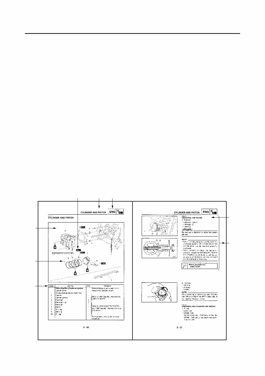
EXPLODED DIAGRAMS
To help identify parts and clarify procedure steps, there are exploded diagrams at the beginning of
each removal and disassembly section.
1. Each section is characterised by an exploded drawing (4) that can be easily understood and that
facilitates assembly and disassembly operations.
2. The numeric references (5) in the exploded drawings show the order of the operations to be car-
ried out. A number inside a circle shows a disassembly phase.
3. The symbols (6) supply precise information easy to be understood about the operations to be
carried out with the relevant notes.
4. The exploded drawing is provided with an instruction box (7) that contains the description of the
sequence of operations to be carried out, the name of the components, the notes, etc.
5. For operations that require further information, a supplement (8) with the description of step-by-
step operations is supplied with the exploded drawings and the instruction box.
4
5
7
1 2 6
3
8
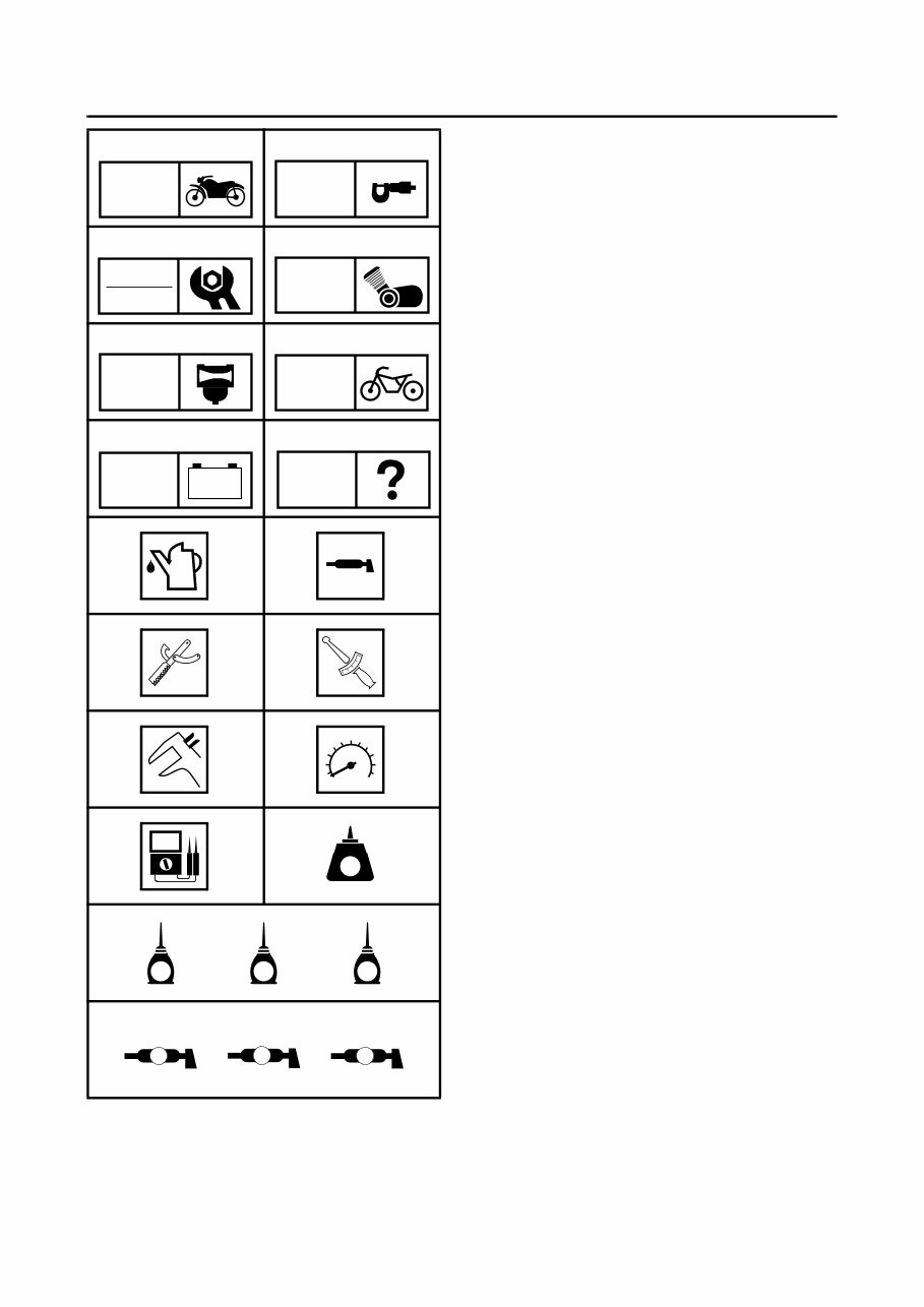
EXPLANATORY SYMBOLS
The explanatory symbols from (1) to (8),
shown in the side figure show the numbers
and the content of the different chapters.
(1) General information
(2) Specifications
(3) Periodic inspections and adjustments
(4) Engine
(5) Carburetor
(6) Chassis
(7) Electrical
(8) Troubleshooting
The explanatory symbols from (9) to (15) show
some specifications that can be found in the
text
(9) Fill up
(10) Lubricant
(11) Special tool
(12) Tighten with torque wrench
(13) Wear limit, clearance
(14) Engine speed
(15) Multimeter Ω, V, A
The explanatory symbols from (16) to (22),
inserted in the exploded drawings show the
type of sealant and/or lubricant and the appli-
cation points
(16) Apply sealant LOCTITE
(17) Apply engine oil
(18) Apply gear oil
(19) Apply molybdenum disulfide oil
(20) Apply bearing grease
(21) Apply lithium-soap base grease
(22) Apply molybdenum disulfide grease
1 2
3 4
5 6
7 8
9 0
A B
C D
E F
G H I
J K L
GEN
INFO
SPEC
INSP
ADJ
ENG
CARB CHAS
– +
ELEC
TRBL
SHT
T
R
.
.
LT
E G M
B
LS M
INDEX
GENERAL INFORMATION
GEN
INFO 1
SPECIFICATIONS
SPEC
2
PERIODIC INSPECTION AND
ADJUSTMENT
INSP
ADJ 3
ENGINE
ENG
4
CARBURETOR
CARB
5
CHASSIS
CHAS
6
ELECTRICAL SYSTEM
ELEC
7
TROUBLESHOOTING
TRBL
SHTG 8
– +

GEN
INFO
CHAPTER 1
GENERAL INFORMATION
MOTORCYCLE IDENTIFICATION .................................................................. 1-1
VEHICLE SERIAL NUMBER ..................................................................... 1-1
MODEL LABEL.......................................................................................... 1-1
IMPORTANT INFORMATION ......................................................................... 1-2
PREPARATION FOR REMOVAL AND DISASSEMBLY........................... 1-2
SPARE PARTS ......................................................................................... 1-3
GASKETS, SEALS AND O-RINGS ........................................................... 1-3
LOCK WASHERS, PLATES AND COTTER PINS .................................... 1-3
BEARINGS AND OIL SEALS .................................................................... 1-3
CIRCLIPS .................................................................................................. 1-4
SPECIAL TOOLS ............................................................................................ 1-5
1 - 1
GEN
INFO
GENERAL INFORMATION
MOTORCYCLE IDENTIFICATION
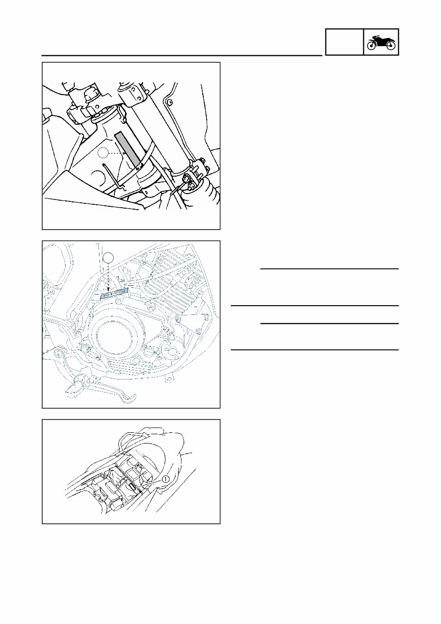
VEHICLE SERIAL NUMBER
The vehicle serial number (1) is stamped on
the right side of the steering sleeve tube.
1
The engine serial number (1) is stamped on
the left side of the crankcase.
NOTE:
The first five figures of the number identify the
engine Code; the other figures show the num-
ber of production of the unit.
NOTE:
Designs and specifications are subject to
change without notice.
1
MODEL LABEL
The model label (1) is applied to the rear mud-
guard. This information is necessary for order-
ing the spare parts.
MOTORCYCLE IDENTIFICATION
1 - 2
GEN
INFO
IMPORTANT INFORMATION
IMPORTANT INFORMATION
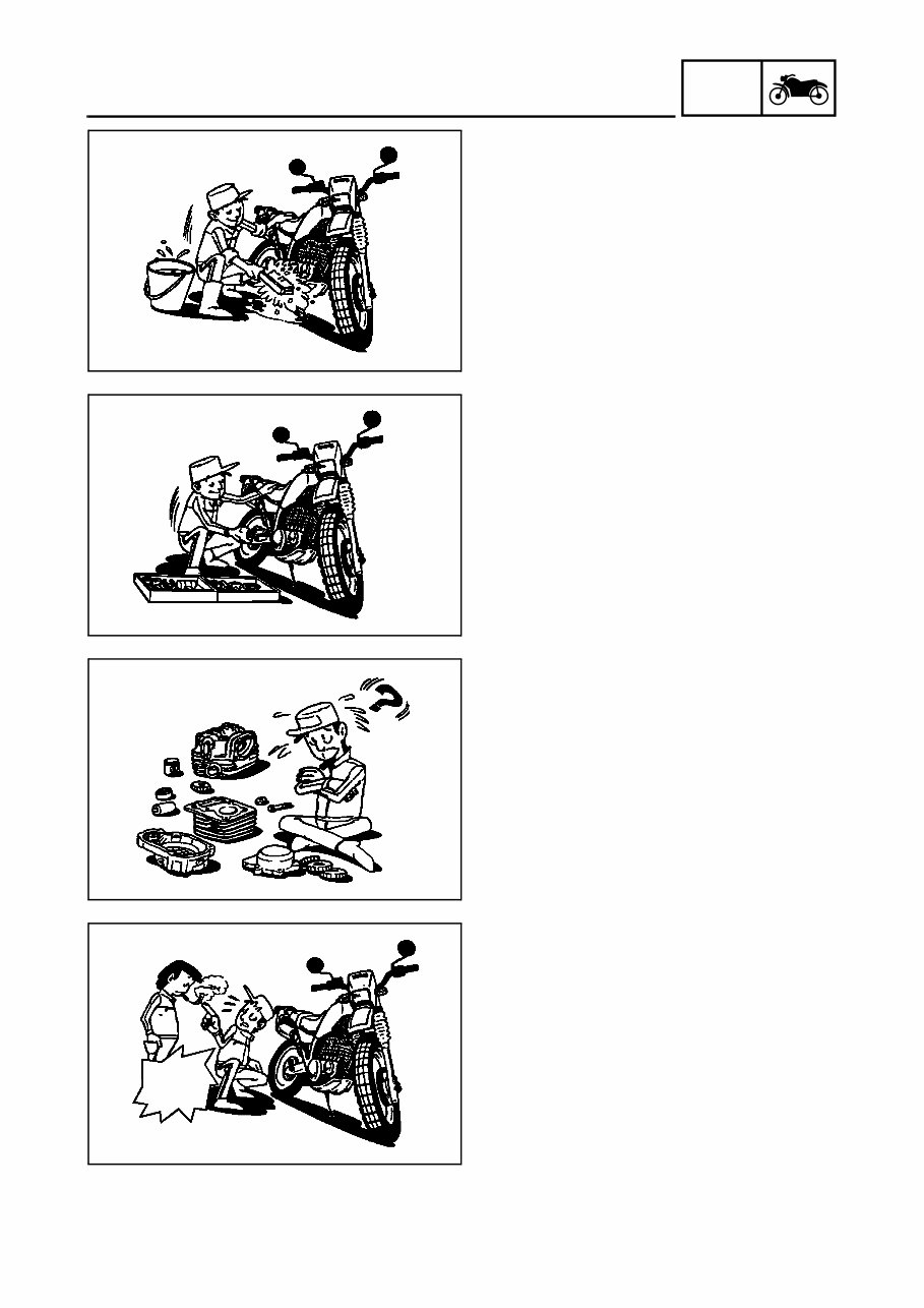
PREPARATION FOR REMOVAL AND
DISASSEMBLY
1. Remove all dirt, mud, dust, and foreign
material before removing and disassem-
bling.
2. Use proper tools and cleaning equipment.
See “SPECIAL TOOLS”.
3. When disassembling the motorcycle, keep
mated parts together. This includes gears,
cylinders, pistons and other mated parts
that wear out with each other. Mated parts
must be reused as an assembly or
replaced.
4. During motorcycle disassembly, clean all
parts and place them in trays the order of
disassembly. This will speed up assembly
time and help assure that all parts are cor-
rectly reinstalled.
5. Keep all components away from fire.
DO NOT
SMOKE

1 - 3
GEN
INFO
IMPORTANT INFORMATION
SPARE PARTS
1. Use only genuine Yamaha parts for all
replacements. Use oil and/or grease recom-
mended by Yamaha for assembly and
adjustment. Other brands may be similar in
function and appearance, but inferior in
quality.
GASKETS, SEALS AND O-RINGS
1. All gaskets, seals and O-rings should be
replaced when an engine is overhauled. All
surfaces in contact with gaskets, oil seal lips
and O-rings must be cleaned.
2. Properly oil all mating parts and bearings
during reassembly. Apply grease to the oil
seal lips.
LOCK WASHERS, PLATES AND COTTER
PINS
1. All lock washers, plates (1) and cotter pins
must be replaced when they are removed.
After proper tightening, lock tabs should be
bent along the bolt or nut.
BEARINGS AND OIL SEALS
1. Install the bearings and oil seals with their
manufacturer’s marks or numbers facing
outward. When installing oil seals, lubricate
a light coating of lithium base grease to the
seal lips. If necessary, lubricate the bear-
ings.
CAUTION:
Do not use compressed air to dry the bear-
ings. This may damage the bearing sur-
faces.
You're Reading a Preview
What's Included?
Fast Download Speeds
Online & Offline Access
Access PDF Contents & Bookmarks
Full Search Facility
Print one or all pages of your manual
$30.99
Viewed 64 Times Today


Secure transaction
What's Included?
Fast Download Speeds
Online & Offline Access
Access PDF Contents & Bookmarks
Full Search Facility
Print one or all pages of your manual
$30.99
This is a comprehensive service and repair manual suitable for PC, MAC, tablets, and smartphones. It provides detailed instructions, wiring diagrams, and images for easy repair jobs, including routine maintenance.
The manual is available in English and is compatible with Win/MAC/Linux. It is instantly accessible upon payment, eliminating the need for shipping. You can start your repair work immediately on your PC, tablet, or laptop.
Frequently Asked Questions:
- Why should I purchase this manual?
This manual offers a user-friendly layout covering detailed repair procedures, enabling better understanding of parts and repair processes. It empowers you to perform your own servicing, maintenance, and repairs. - What models are covered in this manual?
All models for the specified years and engine types are included. - What type of information is covered?
The manual encompasses all aspects of service, repair, and maintenance. - How long for delivery?
Instant delivery upon payment via Credit/Debit/Paypal Account, with no shipping involved. - How much money will I save?
This manual can potentially save you thousands of dollars by enabling you to perform tasks yourself, avoiding overpriced professional services. - Is this Manual hard to use?
No, it is simple to use and compatible with any PC/MAC computer.


