NOTICE 1-1 EAS20070 NOTICE This manual was produced by the Yamaha Motor Company, Ltd. primarily for use by Yamaha dealers and their qualified mechanics. It is not possible to include all the knowledge of a mechanic in one man- ual. Therefore, anyone who uses this book to perform maintenance and repairs on Yamaha vehicles should have a basic understanding of mechanics and the techniques to repair these types of vehicles. Repair and maintenance work attempted by anyone without this knowledge is likely to render the vehi- cle unsafe and unfit for use. This model has been designed and manufactured to perform within certain specifications in regard to performance and emissions. Proper service with the correct tools is necessary to ensure that the vehi- cle will operate as designed. If there is any question about a service procedure, it is imperative that you contact a Yamaha dealer for any service information changes that apply to this model. This policy is intended to provide the customer with the most satisfaction from his vehicle and to conform to federal environmental quality objectives. Yamaha Motor Company, Ltd. is continually striving to improve all of its models. Modifications and sig- nificant changes in specifications or procedures will be forwarded to all authorized Yamaha dealers and will appear in future editions of this manual where applicable. NOTE: ● This Service Manual contains information regarding periodic maintenance to the emission control system. Please read this material carefully. ● Designs and specifications are subject to change without notice. EAS20080 IMPORTANT MANUAL INFORMATION Particularly important information is distinguished in this manual by the following. The Safety Alert Symbol means ATTENTION! BECOME ALERT! YOUR SAFETY IS INVOLVED! Failure to follow WARNING instructions could result in se v ere injur y or death to the vehicle operator, a bystander or a person checking or repairing the vehicle. A CAUTION indicates special precautions that must be taken to avoid damage to the vehicle. A NOTE provides key information to make procedures easier or clearer. WARNING CAUTION: NOTE:
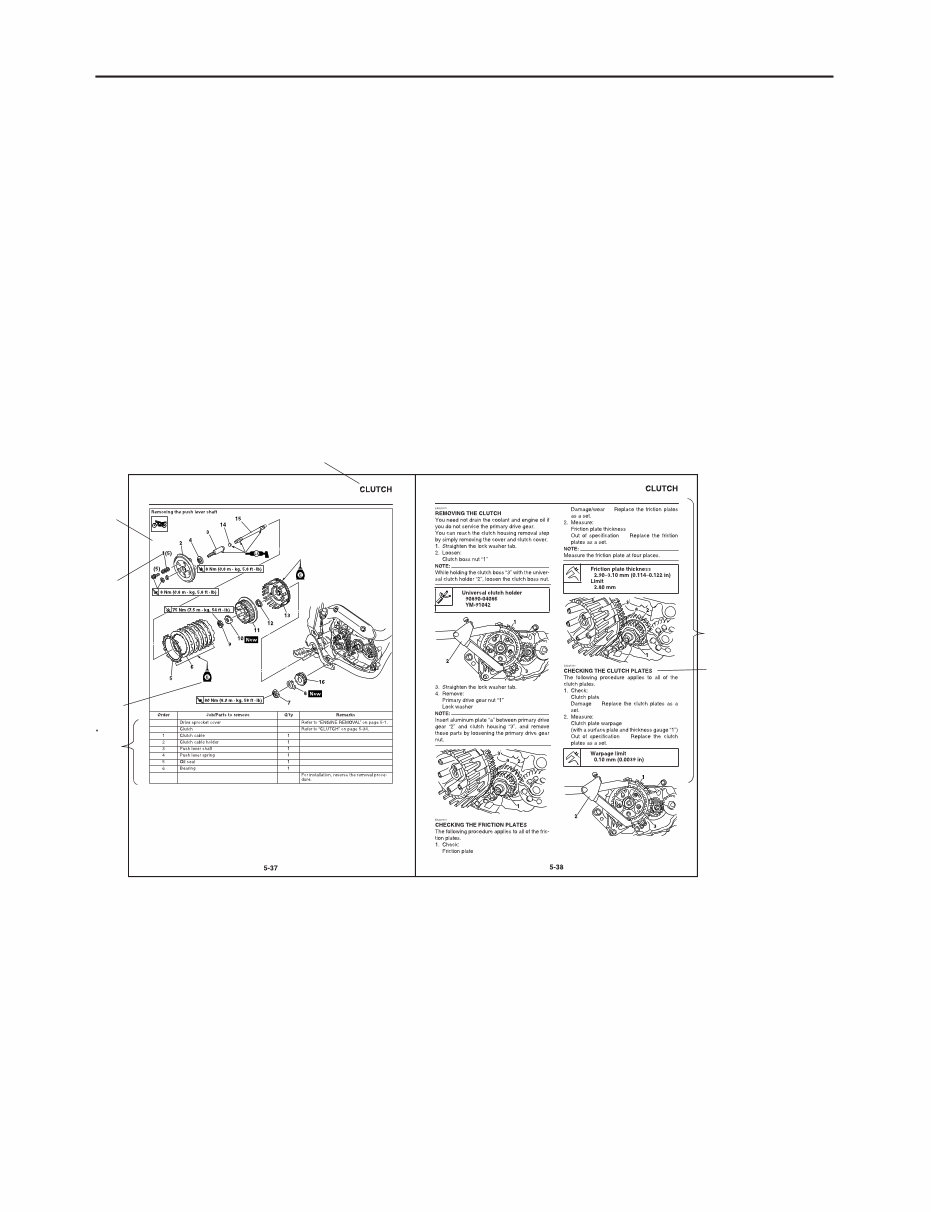
HOW TO USE THIS MANUAL 1-2 EAS20090 HOW TO USE THIS MANUAL This manual is intended as a handy, easy-to-read reference book for the mechanic. Comprehensive explanations of all installation, removal, disassembly, assembly, repair and check procedures are laid out with the individual steps in sequential order. ● The manual is divided into chapters and each chapter is divided into sections. The current section title is shown at the top of each page “1”. ● Sub-section titles appear in smaller print than the section title “2”. ● To help identify parts and clarify procedure steps, there are exploded diagrams at the start of each removal and disassembly section “3”. ● Numbers are given in the order of the jobs in the exploded diagram. A number indicates a disassem- bly step “4”. ● Symbols indicate parts to be lubricated or replaced “5”. Refer to “SYMBOLS”. ● A job instruction chart accompanies the exploded diagram, providing the order of jobs, names of parts, notes in jobs, etc “6”. ● Jobs requiring more information (such as special tools and technical data) are described sequentially “7”. 3 4 5 6 7 1 2
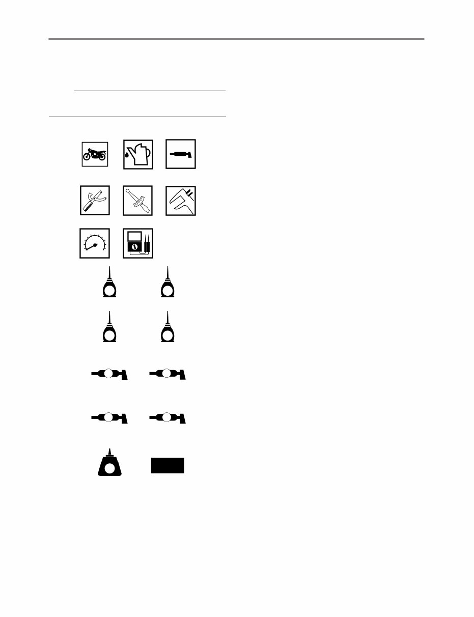
SYMBOLS 1-3 EAS20100 SYMBOLS The following symbols are used in this manual for easier understanding. NOTE: The following symbols are not relevant to every vehicle. G M E B LS M 9 10 11 12 13 14 15 16 17 18 LT New BF S T R . . 1 2 3 4 5 6 7 8 1. Serviceable with engine mounted 2. Filling fluid 3. Lubricant 4. Special tool 5. Tightening torque 6. Wear limit, clearance 7. Engine speed 8. Electrical data 9. Engine oil 10. Gear oil 11. Molybdenum-disulfide oil 12. Brake fluid 13. Wheel-bearing grease 14. Lithium-soap-based grease 15. Molybdenum-disulfide grease 16. Silicone grease 17. Apply locking agent (LOCTITE®) 18. Replace the part
GENERAL INFORMATION 1 SPECIFICATIONS 2 PERIODIC CHECKS AND ADJUSTMENTS 3 CHASSIS 4 ENGINE 5 COOLING SYSTEM 6 FUEL SYSTEM 7 ELECTRICAL SYSTEM 8 TROUBLESHOOTING 9 EAS20110 TABLE OF CONTENTS
1 2 3 4 5 6 7 8 9 GENERAL INFORMATION IDENTIFICATION ...........................................................................................1-1 VEHICLE IDENTIFICATION NUMBER ....................................................1-1 MODEL LABEL ........................................................................................1-1 FEATURES ....................................................................................................1-2 OUTLINE OF THE FI SYSTEM................................................................1-2 FI SYSTEM ..............................................................................................1-3 MULTI-FUNCTION DISPLAY...................................................................1-4 IMPORTANT INFORMATION ........................................................................1-8 PREPARATION FOR REMOVAL AND DISASSEMBLY .........................1-8 REPLACEMENT PARTS .........................................................................1-8 GASKETS, OIL SEALS AND O-RINGS ...................................................1-8 LOCK WASHERS/PLATES AND COTTER PINS ....................................1-8 BEARINGS AND OIL SEALS ...................................................................1-8 CIRCLIPS .................................................................................................1-9 CHECKING THE CONNECTIONS .................................................................1-10 SPECIAL TOOLS ...........................................................................................1-11
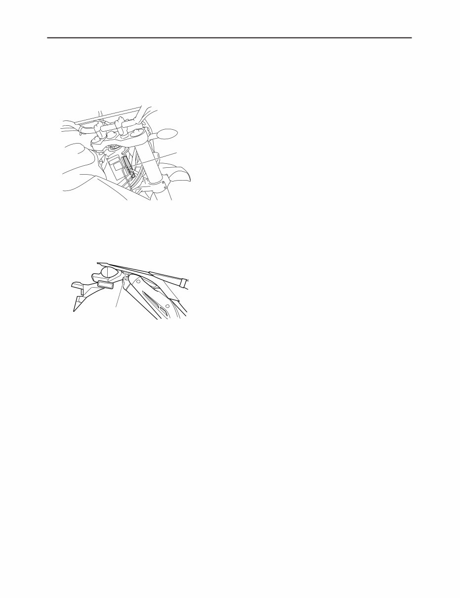
IDENTIFICATION 1-1 EAS20130 IDENTIFICATION EAS20140 VEHICLE IDENTIFICATION NUMBER The vehicle identification number “1” is stamped into the right side of the steering head pipe. EAS20150 MODEL LABEL The model label “1” is affixed to the frame. This information will be needed to order spare parts. 1 1
You're Reading a Preview
What's Included?
Lifetime Access
Fast Download Speeds
Online & Offline Access
Access PDF Contents & Bookmarks
Full Search Facility
Print one or all pages of your manual
$41.99
2008-2012 Yamaha WR250R WR250X Motorcycle Service & Repair Manual
Thank you for considering this comprehensive Workshop Service Repair Manual for the Yamaha WR250R WR250X Motorcycle, covering the years 2008 to 2012.
This manual is an invaluable resource for both professional mechanics and DIY enthusiasts, providing detailed instructions and illustrations for every Service & Repair Procedure.
By utilizing this manual, you can significantly reduce expenses by performing your own repairs. The step-by-step instructions and images make every service or repair job easy to understand and execute.
Upon acquisition, this manual becomes your permanent asset. You have the flexibility to print individual pages, specific chapters, or the entire manual. Additionally, you can conveniently access it on your tablet or smartphone.
All Models/Engines/Trim/Transmissions Types are comprehensively covered in this high-quality Service Repair Workshop Manual, encompassing all repair procedures from A-Z.
Compatible with all PC & MAC Computers, tablets, and mobile phones, this downloadable manual requires only adobe reader, which is commonly pre-installed. Alternatively, it can be obtained for free.
Upon payment via Visa, MasterCard, or PayPal, the manual will be promptly emailed to your provided email address, ensuring instant delivery.
Rest assured, customer satisfaction is guaranteed with this Workshop Service Repair Manual.
Reviews
Q&A
Recently Viewed
5,521,897Happy Clients
2,594,462eManuals
1,120,453Trusted Sellers
15Years in Business
Price:
Actual Price:
2008-2012 Yamaha WR250R WR250X Motorcycle Service & Repair Manual






 Lifetime Access




