

2024 Yamaha Tracer 9 GT Service & Repair Manual
What's Included?
Fast Download Speeds
Online & Offline Access
Access PDF Contents & Bookmarks
Full Search Facility
Print one or all pages of your manual
@SYAMAHA
SERVICEMANUAL
Tracer9GT+
2024
MTT9GPR
MTT9GPRC
LIT-11616-37-16

@YAMAHA
SERVICEMANUAL
BASICINFORMATION
LIT-11616-MC-BOYOA-28197-10

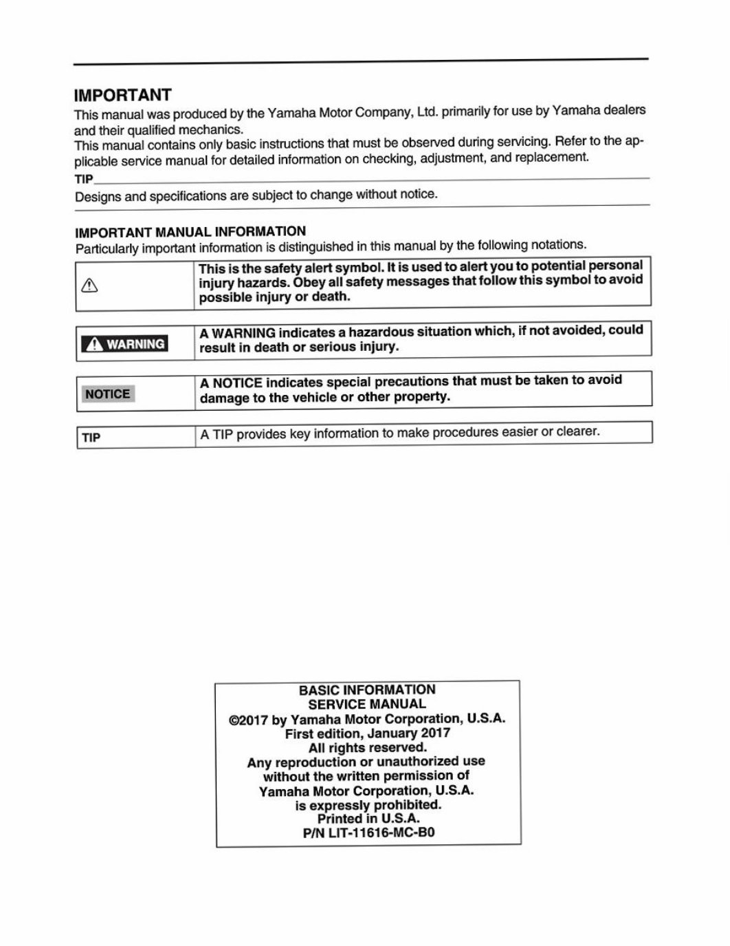
IMPORTANT
ThismanualwasproducedbytheYamahaMotorCompany,Ltd.primarilyforusebyYamahadealers
andtheirqualifiedmechanics.
Thismanualcontainsonlybasicinstructionsthatmustbeobservedduringservicing.Refertotheap-
plicableservicemanualfordetailedinformationonchecking,adjustment,andreplacement.
TIP.
Designsandspecificationsaresubjecttochangewithoutnotice.
IMPORTANTMANUALINFORMATION
Particularlyimportantinformationisdistinguishedinthismanualbythefollowingnotations.
Thisisthesafetyalertsymbol.Itisusedtoalertyoutopotentialpersonal
a&dinjuryhazards.Obeyallsafetymessagesthatfollowthissymboltoavoid
possibleinjuryordeath.
]AWARNINGindicatesahazardoussituationwhich,ifnotavoided,could
WATZENIT_resultindeathorseriousinjury.
‘ANOTICEindicatesspecialprecautionsthatmustbetakentoavoid
NOTICEdamagetothevehicleorotherproperty.
TIPATIPprovideskeyinformationtomakeprocedureseasierorclearer.
BASICINFORMATION
SERVICEMANUAL
©2017byYamahaMotorCorporation,U.S.A.
Firstedition,January2017
Allrightsreserved.
Anyreproductionorunauthorizeduse
withoutthewrittenpermissionof
YamahaMotorCorporation,U.S.A.
isexpresslyprohibited.
PrintedinU.S.A.
PINLIT-11616-MC-BO
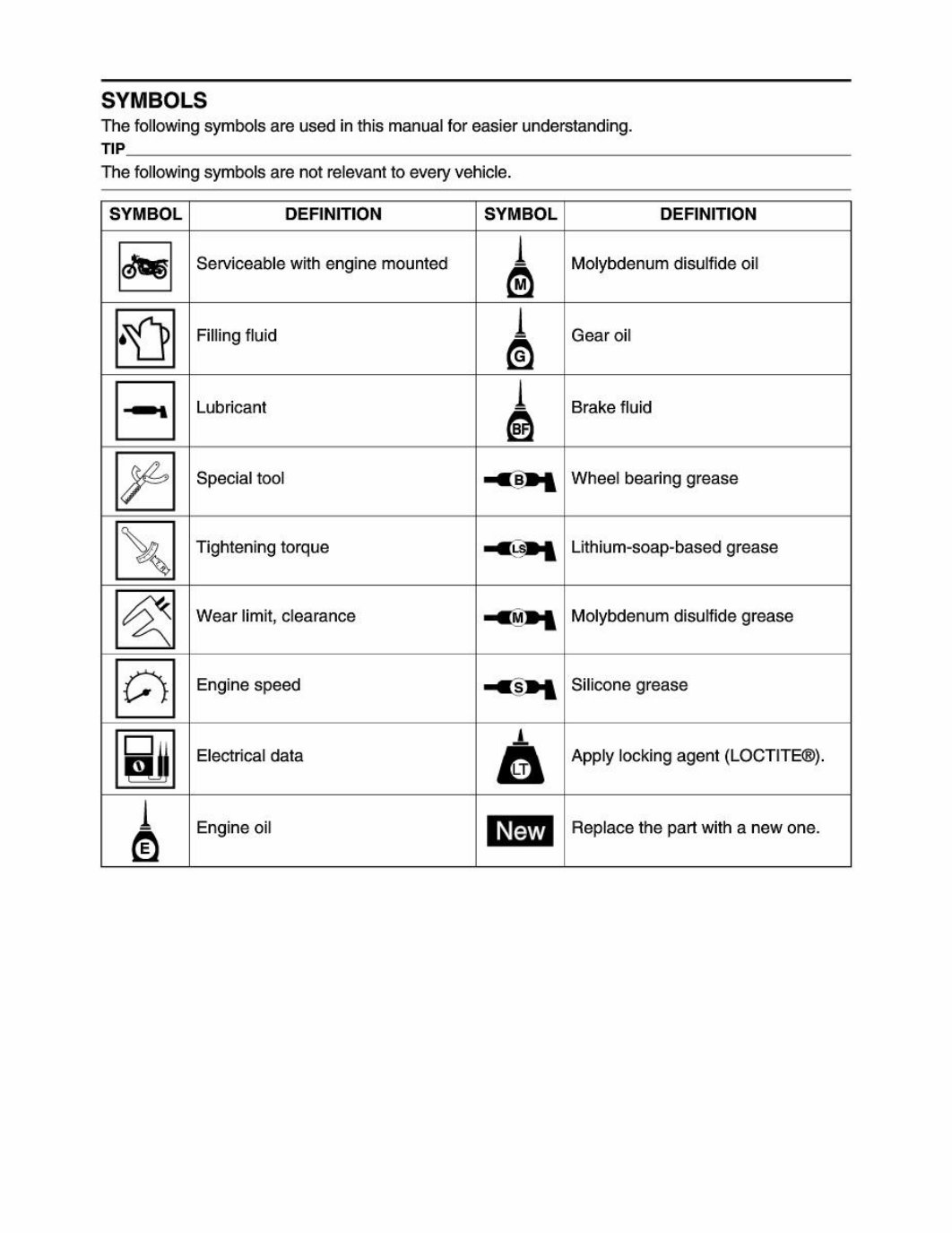
SYMBOLS
Thefollowingsymbolsareusedinthismanualforeasierunderstanding.
TIP.
Thefollowingsymbolsarenotrelevanttoeveryvehicle.
SYMBOL DEFINITION SYMBOL DEFINITION
Serviceablewithenginemounted Molybdenumdisulfideoil
p-— |© Tae _p-
FillingfluidGearoil
LubricantBrakefluid
SpecialtoolWheelbearinggrease
Tighteningtorque
<4
Lithium-soap-basedgrease
Wearlimit,clearance
«14
Molybdenumdisulfidegrease
Enginespeed
“ashy
Siliconegrease
Electricaldata Applylockingagent(LOCTITE®).
(HS |p] SJL Ica a
Engineoil Replacethepartwithanewone.
CONTENTS
IMPORTANTINFORMATION...
PREPARATIONFORREMOVALANDDISASSEMBLY.
REPLACEMENTPARTS...
GASKETS,OILSEALSANDO-RINGS ..
LOCKWASHERS/PLATESANDCOTTERPINS
BEARINGSANDOILSEALS...
CIRCLIPS....
REASSEMBLYOFPARTSUSINGLOCKINGAGENT(LOCTITE®)
RUBBERPARTS..
BASICSERVICEINFORMATION.
QUICKFASTENERS..
ELECTRICALSYSTEM
GENERALTIGHTENINGTORQUESPECIFICATIONS.
ADJUSTINGTHEWHEELSTATICBALANCE
CHECKINGTHESWITCHES....
CHECKINGTHEBULBSANDBULBSOCKETS.
CHECKINGANDCHARGINGTHEBATTERY...
TROUBLESHOOTING...
GENERALINFORMATION.
TROUBLESHOOTINGOFENGINE(faultcodenotdetected)
TROUBLESHOOTINGOFCLUTCH...
TROUBLESHOOTINGOFTRANSMISSION
TROUBLESHOOTINGOFCOOLINGSYSTEM.
TROUBLESHOOTINGOFBRAKE...32
TROUBLESHOOTINGATABSWARNINGLIGHT.33
TROUBLESHOOTINGOFSUSPENSION ..34
TROUBLESHOOTINGOFSTEERING/HANDLING36
TROUBLESHOOTINGOFCHARGINGSYSTEM.
TROUBLESHOOTINGOFLIGHTINGSYSTEM.
TROUBLESHOOTINGOFSIGNALINGSYSTEM.
IMPORTANTINFORMATION
IMPORTANTINFORMATION
PREPARATIONFORREMOVALAND
DISASSEMBLY
1.Beforeremovalanddisassembly,removeall
dirt,mud,dustandforeignmaterial.
2.Useonlythepropertoolsandcleaningequip-
ment.
Referto“SPECIALTOOLS?’intheapplicable
servicemanual.
3.Whendisassembling,alwayskeepmated
partstogether.Thisincludesgears,cylinders,
pistonsandotherpartsthathavebeen“mat-
ed”throughnormalwear.Matedpartsmust
alwaysbereusedorreplacedasanassem-
bly.
4.Duringdisassembly,cleanallofthepartsand
placethemintraysintheorderofdisassem-
bly.Thiswillspeedupassemblyandallowfor
thecorrectinstallationofallparts.
5.Keepallpartsawayfromanysourceoffire.
REPLACEMENTPARTS
UseonlygenuineYamahapartsforallreplace-
ments.Useoilandgreaserecommendedby
Yamahaforalllubricationjobs.Otherbrands
maybesimilarinfunctionandappearance,but
inferiorinquality.
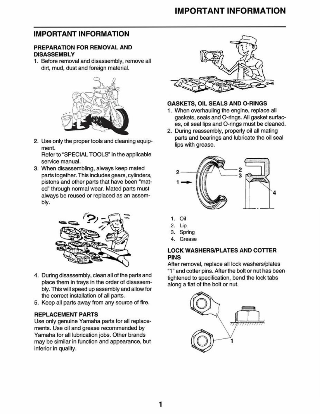
GASKETS,OILSEALSANDO-RINGS
1.Whenoverhaulingtheengine,replaceall
gaskets,sealsandO-rings.Allgasketsurfac-
es,oilseallipsandO-ringsmustbecleaned.
2.Duringreassembly,properlyoilallmating
partsandbearingsandlubricatetheoilseal
lipswithgrease.
1.Oil
2.Lip
3.Spring
4,Grease
LOCKWASHERS/PLATESANDCOTTER
PINS
Afterremoval,replacealllockwashers/plates
“1”andcotterpins.Aftertheboltornuthasbeen
tightenedtospecification,bendthelocktabs
alongaflatoftheboltornut.
IMPORTANTINFORMATION
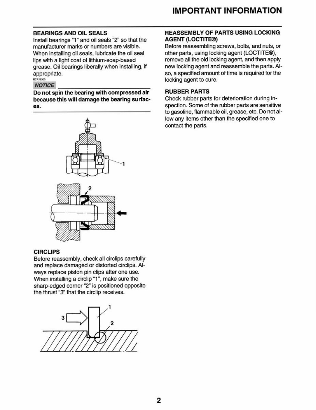
BEARINGSANDOILSEALS
Installbearings“1”andoilseals“2”sothatthe
manufacturermarksornumbersarevisible.
Wheninstallingoilseals,lubricatetheoilseal
lipswithalightcoatoflithium-soap-based
grease.Oilbearingsliberallywheninstalling,if
appropriate.
NOTICE
Donotspinthebearingwithcompressedair
becausethiswilldamagethebearingsurfac-
es.
CIRCLIPS
Beforereassembly,checkallcirclipscarefully
andreplacedamagedordistortedcirclips.Al-
waysreplacepistonpinclipsafteroneuse.
Wheninstallingacirclip“1”,makesurethe
sharp-edgedcomer“2”ispositionedopposite
thethrust“3”thatthecirclipreceives.
REASSEMBLYOFPARTSUSINGLOCKING
AGENT(LOCTITE®)
Beforereassemblingscrews,bolts,andnuts,or
otherparts,usinglockingagent(LOCTITE®),
removealltheoldlockingagent,andthenapply
newlockingagentandreassembletheparts.Al-
0,aspecifiedamountoftimeisrequiredforthe
lockingagenttocure.
RUBBERPARTS
Checkrubberpartsfordeteriorationduringin-
spection.Someoftherubberpartsaresensitive
togasoline,flammableoil,grease,etc.Donotal-
lowanyitemsotherthanthespecifiedoneto
contacttheparts.
BASICSERVICEINFORMATION
BASICSERVICEINFORMATION
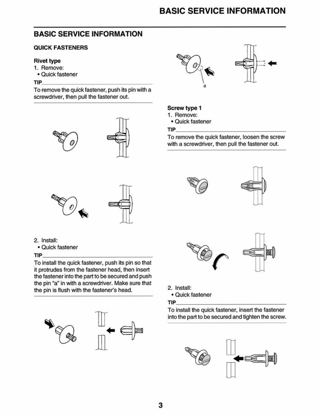
QUICKFASTENERS
Rivettype
1.Remove:
*Quickfastener
TIP.
Toremovethequickfastener,pushitspinwitha
‘screwdriver,thenpullthefastenerout.
3a
2.Install:
*Quickfastener
TIP.
Toinstallthequickfastener,pushitspinsothat
itprotrudesfromthefastenerhead,theninsert
thefastenerintotheparttobesecuredandpush
thepin“a”inwithascrewdriver.Makesurethat
thepinisflushwiththefastener’shead.
*93-Gz
We
\ALL
a
Screwtype1
1.Remove:
*Quickfastener
TIP.
Toremovethequickfastener,loosenthescrew
withascrewdriver,thenpullthefastenerout.
eo6
er
2.Install:
*Quickfastener
TIP.
Toinstallthequickfastener,insertthefastener
intotheparttobesecuredandtightenthescrew.
UD,
Ye=
You're Reading a Preview
What's Included?
Fast Download Speeds
Online & Offline Access
Access PDF Contents & Bookmarks
Full Search Facility
Print one or all pages of your manual
$57.99
Viewed 37 Times Today


Secure transaction
What's Included?
Fast Download Speeds
Online & Offline Access
Access PDF Contents & Bookmarks
Full Search Facility
Print one or all pages of your manual
$57.99
The Yamaha Tracer 9 GT Service & Repair Manual is a comprehensive guide designed for both professional mechanics and DIY enthusiasts. This manual provides detailed instructions on troubleshooting, repair, and maintenance procedures for the motorcycle.
- This manual covers a wide range of topics, including technical specifications, diagrams, and step-by-step guides for various tasks
- It is an essential resource for anyone looking to understand and maintain their Yamaha Tracer 9 GT
- Suitable for both amateur and professional mechanics
- This manual provides in-depth information on the motorcycle's inner workings, allowing users to diagnose and repair issues with confidence
- A valuable resource for anyone looking to work on their own vehicle or equipment


