

Yamaha Rx135 Parts Catalog
What's Included?
Fast Download Speeds
Online & Offline Access
Access PDF Contents & Bookmarks
Full Search Facility
Print one or all pages of your manual
4TL1/2
Parts & Accessories
RX 135 INDIA

RX 135 (4TL1/2)
PARTS CATALOGUE
All rights reserved.
Any reprinting or unauthorized use
without the written permission of
is expressly prohibited.
Printed in INDIA
INDIA YAMAHA MOTOR PVT. LTD.
INDIA YAMAHA MOTOR PVT. LTD.

This Parts Catalogue is related to the parts in use for the YAMAHA - RX 135 (4TL1)
When you are ordering replacement parts for RX 135 (4TL1) refer to this Parts
Catalogue and quote both part numbers and part names correctly.
1. Modifications or additions which have been made after issue of the Parts
Catalogue will be announced in the Service Actions. It is advisible that according
to the Service Action you make necessary corrections tothe Parts Catalogue on
hand to keep it up-to-date.
2. Indication of No. of constituent parts for assembly.
The numeral appearing to the right of each constituent part under the description
indicates the quantity of such parts for each individual assembly unit.
EXAMPLE
Part No. Description Qty
2YA-XE1400-00 CRANK SHAFT ASSY. 1
36L-H2110-01 BATTERY ASSY 1
4TL-E1111-10 CYLINDER HEAD 1
3. Applicable Serial No. and Color Code
NOTICE
The description and illustration in this Parts Catalogue may not necessarily match
with the physical appearance of the parts.
INDIA YAMAHA MOTOR PVT. LTD. reserves the right to carry out modifications on the
vehicle, parts or accessories, as may be considered necessary, without being
obliged to update this Parts Catalogue immediately.
No part of this Publication may be reproduced without written permission of
INDIA YAMAHA MOTOR PVT. LTD.
FOREWORD
Colour Code Colour Name Abbreviate
01H9 YAMAHA BLACK YB
01H6 MAROON CNM
019V BLUE BL
1

ENGINE
CYLINDER ....................................................... 2
CRANKSHAFT/PISTON ..................................... 3
OIL PUMP ........................................................ 4
INTAKE ............................................................ 5
CARBURETTOR ................................................ 7
EXHAUST ......................................................... 9
CRANKCASE .................................................. 10
CRANKCASE COVER 1 ..................................... 11
STARTER . ......................................................... 12
CLUTCH ......................................................... 13
TRANSMISSION ............................................. 14
SHIFT CAM FORK .......................................... 15
SHIFT SHAFT .................................................. 16
CHASSIS
FRAME ............................................................ 17
FENDER .......................................................... 18
SIDE COVER .................................................. 19
OIL TANK ........................................................... 20
REAR ARM. & SUSPENSION ............................ 21
STEERING ...................................................... 22
FRONT FORK ................................................. 23
FUEL TANK ..................................................... 25
DOUBLE SEAT..................................................... 27
FRONT WHEEL ... .............................................. 28
REAR WHEEL ... ................................................ 30
HANDLE & CABLE ............................................. 32
STAND FOOTREST ... ........................................ 33
GENERATOR .................................................. 35
FLASHER LIGHT ............................................. 36
METER ........................................................... 37
HEAD LIGHT ................................................... 38
TAIL LIGHT ....................................................... 39
HANDLE SWITCH & LEVER .............................. 40
ELECTRICAL 1 ............................................... 41
ELECTRICAL 2 ............................................... 42
OPTIONAL PARTS ............................................. 43
NUMERICAL INDEX
CONTENTS
4TL1
REF.
NO.
EXISTING
PART NO.
PART NAME
REMARKS
2
SUPERSEDED
PART NO.
ESCORT
12 DIGIT
9 DIGIT
PART NO.
NOTE :-
1) Requested to create the parts order in existing part no. i.e in 12 digit
2) Part numbers having no symbol in remarks column indicates its serviceability
A) Part nos with symbol (Δ) are serviceable till stock
B) Part nos with symbol (#) are not serviceable due to constraints
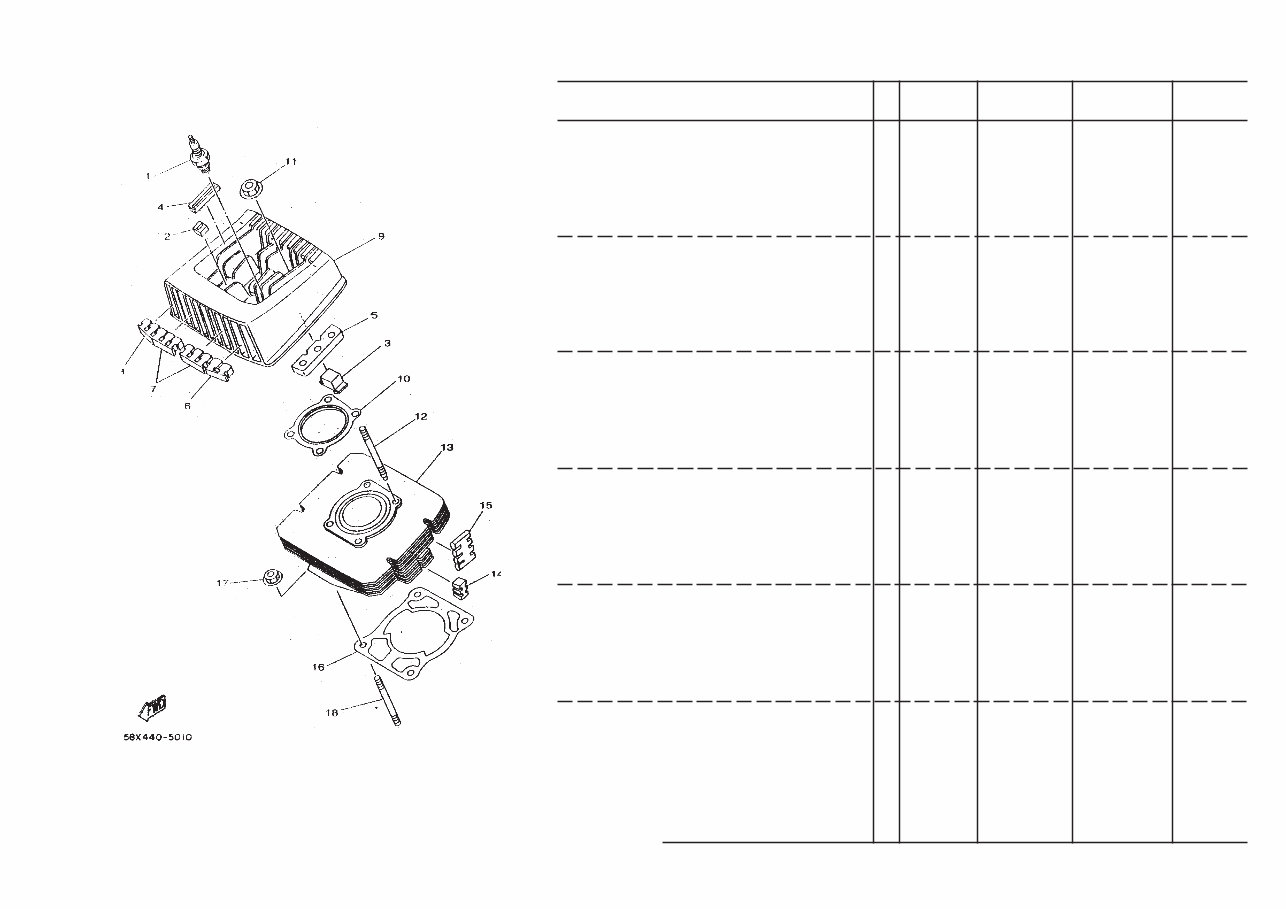
FIG. 1 CYLINDER
1 947030083000 SPARK PLUG-NGK-BPR7HS 1 000024204 947000022700
2 36LE11270000 ABSORBER-3 6 1L1520006
3 4TLE11280000 ABSORBER-4 2 1L5520007
4 4TLE11270000 ABSORBER-4 2 1L5520003
5 4TLE11281000 ABSORBER-6 2 1L5520004
6 4TLE11620000 ABSORBER-2 1 1L5520006
7 2YAE11290000 ABSORBER-5 4 1M1520005
8 4TLE11610000 ABSORBER-1 1 1L5520005
9 4TLE11111000 CYLINDER HEAD 1 1L5520002 1L5520002X00 #
10 4TLE11810000 GASKET CYL. HEAD 1 1 1L5520001
11 901790841000 NUT 4 000004309
12 901160839300 BOLT STUD 4 1L1520011
13 4TLE13110000 BODY CYL.RXG/Z 1 1L5520100 #
14 36LE11610000 ABSORBER-1 4 1L1520104
15 4TLE11611000 ABSORBER-9 4 1L5520009
16 36LE13510000 GASKET CYLINDER 1 1L1520003
17 901791081200 NUT 4 1L1520008
18 901161027800 BOLT STUD 4 1L1520010
4TL1
REF.
NO.
EXISTING
PART NO.
PART NAME
REMARKS
3
SUPERSEDED
PART NO.
ESCORT
12 DIGIT
9 DIGIT
PART NO.
NOTE :-
1) Requested to create the parts order in existing part no. i.e in 12 digit
2) Part numbers having no symbol in remarks column indicates its serviceability
A) Part nos with symbol (Δ) are serviceable till stock
B) Part nos with symbol (#) are not serviceable due to constraints
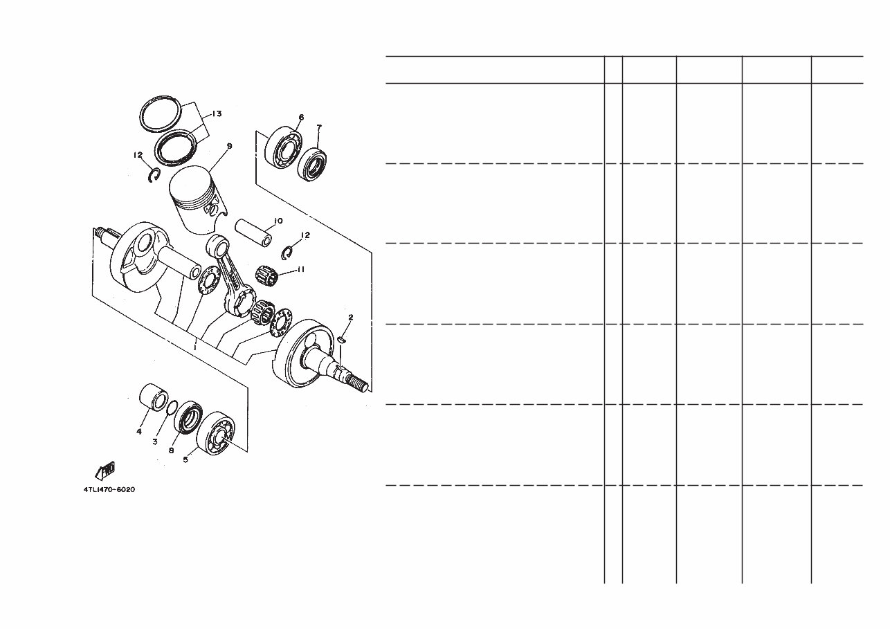
FIG.2 CRANKSHAFT,PISTON
1 2YAXE1400000 CRANK ASSY 1 1M1540100
2 902800301700 KEY WOODRUFF 1 1L1540001
3 932101802300 O RING 1 1L1540002
4 90387205E900 COLLAR 1 1L1540003
5 93306304Y200 BEARING 1 1L1540005
6 93306205Y000 BEARING 1 1L1540004
7 931022580700 OIL SEAL 1 1L1540006
8 931032880000 OIL SEAL 1 1L1540007
9 4TLE16310000 PISTON STD 1 1L5540100 #
4TL116350000 PISTON O/S(.25 MM) 1 1L5540200 #
4TL116360000 PISTON O/S(.0.50 MM ) 1 1L5540300 #
10 2YAE16330000 PIN PISTON 1 1M1540001
11 93310216J200 BEARING CYLINDERICAL 1 1M1541200
12 934501712900 CIRCLIP 2 1L5540004
13 4TLE16030000 PISTON RING SET (STD) 2 1L5540400
4TLE16040000 PISTON RING SET (0.25MM O-S) 1 1L5540500
4TLE16050000 PISTON RING SET (0.50MM O-S) 1 1L5540600
4TL1
REF.
NO.
EXISTING
PART NO.
PART NAME
REMARKS
4
SUPERSEDED
PART NO.
ESCORT
12 DIGIT
9 DIGIT
PART NO.
NOTE :-
1) Requested to create the parts order in existing part no. i.e in 12 digit
2) Part numbers having no symbol in remarks column indicates its serviceability
A) Part nos with symbol (Δ) are serviceable till stock
B) Part nos with symbol (#) are not serviceable due to constraints
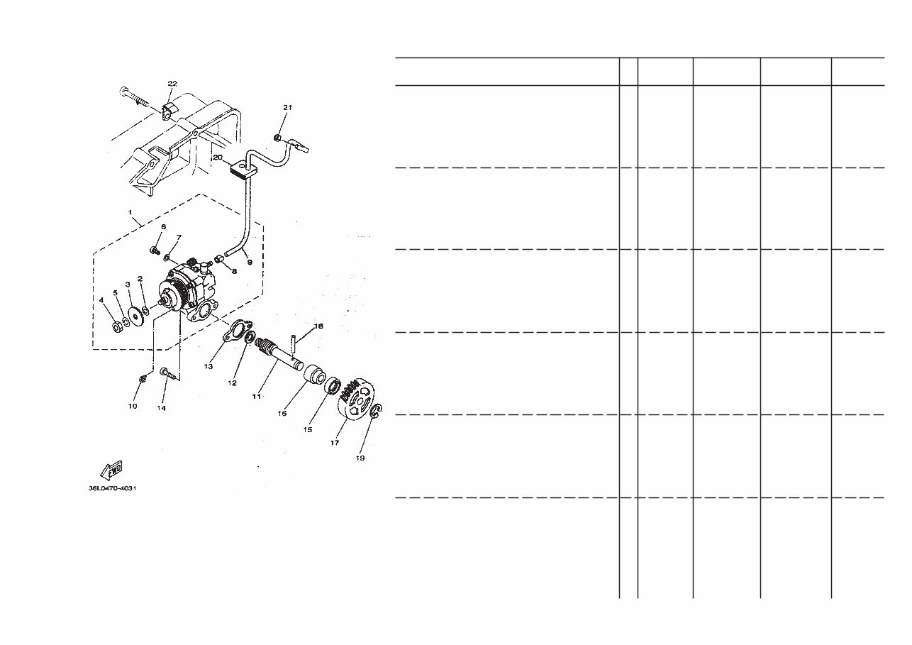
1 4TLE31001000 OIL PUMP ASSY 1 1L5630100 1L5630100X00 #
2 36LE31370005 SHIM PLUNGER 1 1A1630115 Δ
36LE31370005 SHIM PLUNGER 1 1A1630116 Δ
36LE31370010 SHIM PLUNGER 1 1A1630117 Δ
3 PLATE,ADJUSTING 1 #
4 9530M0560000 NUT HEX 1 000004105 Δ
5 9290N0510000 SPRING WASHER 5.5 1 000005110
6 9890N0400800 SCREW BIND 1 000034207 Δ
7 904300400400 GASKET 1 1A1630104
8 904680203300 CLIP 1 1A1630008
9 904452155200 HOSE 1 1L5630101
10 2YAE31330000 CLIP 1 1M1630001 #
11 36LE31750100 SHAFT WORM 1 1L1630002
12 902010862400 WASHER PLATE 1 1A1630002
13 36LE31160000 GASKET PUMP 1 1A1630006
14 9850N0501400 CRPH SCREW 2 000032265 985800501400 Δ
15 931011080600 OIL SEAL 1 1A1630005
16 36LE31760000 BUSH SPACING 1 1A1630004
17 36LE31780000 GEAR DRIVE 1 1L1630003
18 936032280500 PIN DOWEL 1 1A1590013
19 934300881000 CIRCLIP 1 000016311
20 36LE31740000 HOLDER OIL PIPE 1 1L1630004
21 904680203300 CLIP 1 1A1630008
22 904611007100 CLAMP 1 1L163005
FIG.3 OIL PUMP

4TL1
REF.
NO.
EXISTING
PART NO.
PART NAME
REMARKS
5
SUPERSEDED
PART NO.
ESCORT
12 DIGIT
9 DIGIT
PART NO.
NOTE :-
1) Requested to create the parts order in existing part no. i.e in 12 digit
2) Part numbers having no symbol in remarks column indicates its serviceability
A) Part nos with symbol (Δ) are serviceable till stock
B) Part nos with symbol (#) are not serviceable due to constraints
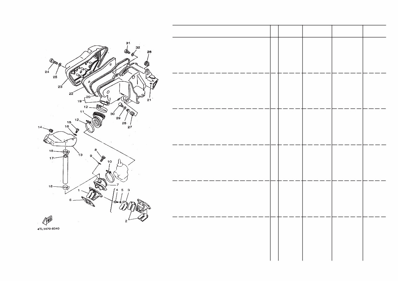
1 2YAE36100000 REED VALVE ASSY 1 1M1140300
2 2YAE36131000 REED, VALVE 2 1M1140301 #
3 36LE36160000 STOPPER, REED VALVE 2 1A1520202 #
4 985070300800 SCREW PAN HEAD 4 000034206 #
5 929060310000 SPRING WASHER 4 000005101 #
6 36LE36210000 GASKET REED VALVE 1 1A1520005
7 2YAE35650000 JOINT CARBURETTOR 1 1M1140200
8 970170602500 BOLT HEXAGON 4 000202107
9 929070660000 WASHER 4 000006204
10 904604305300 CLAMP ASSY 1 1A1520600
11 36LE44530000 JOINT 1 1 1L1140002
12 904604905800 CLAMP HOSE 2 1L1140700
13 2YAE35810000 AIR CHAMBER 1 1M1140001
14 904801205300 GROMMET 1 1L1140003
15 9850N0601600 PAN HEAD SCREW (C) 1 000034222 985070601600
16 902010655700 WASHER 1 000006407
17 904452155200 HOSE 1 1M1140003
18 904672005000 CLIP 2 1M1140004
19 36LE44012000 AIR FILTER CASE ASSY 1 1L2140300
20 36LE44760100 SEAL 1 1L1140401 36LE44760000
21 36LE44240000 CLIP 1 1L1140402
22 36LE44510100 FILTER ELEMENT 1 1 1L5140101 4TLE44510000
23 36LE44020000 CAP CASE ASSY 1 1L1140600
24 9850N0604000 SCREW CHEESE HEAD 3 000034227 985070604000
25 929070620000 WASHER 3 000006304
26 904801205300 GROMMET 1 1L1140003
27 904801410200 GROMMET 1 1L1140004
28 903870739000 COLLAR 1 1L1140001
FIG. 4 INTAKE
4TL1
REF.
NO.
EXISTING
PART NO.
PART NAME
REMARKS
6
SUPERSEDED
PART NO.
ESCORT
12 DIGIT
9 DIGIT
PART NO.
NOTE :-
1) Requested to create the parts order in existing part no. i.e in 12 digit
2) Part numbers having no symbol in remarks column indicates its serviceability
A) Part nos with symbol (Δ) are serviceable till stock
B) Part nos with symbol (#) are not serviceable due to constraints
FIG. 4 INTAKE
29 902010655700 WASHER 1 000006407
30 970170602500 BOLT HEXAGON 1 000002107
31 9850N0601600 PAN HEAD SCREW (C) 1 000034222 985070601600
32 902010655700 WASHER 1 000006407
4TL1
REF.
NO.
EXISTING
PART NO.
PART NAME
REMARKS
7
SUPERSEDED
PART NO.
ESCORT
12 DIGIT
9 DIGIT
PART NO.
NOTE :-
1) Requested to create the parts order in existing part no. i.e in 12 digit
2) Part numbers having no symbol in remarks column indicates its serviceability
A) Part nos with symbol (Δ) are serviceable till stock
B) Part nos with symbol (#) are not serviceable due to constraints
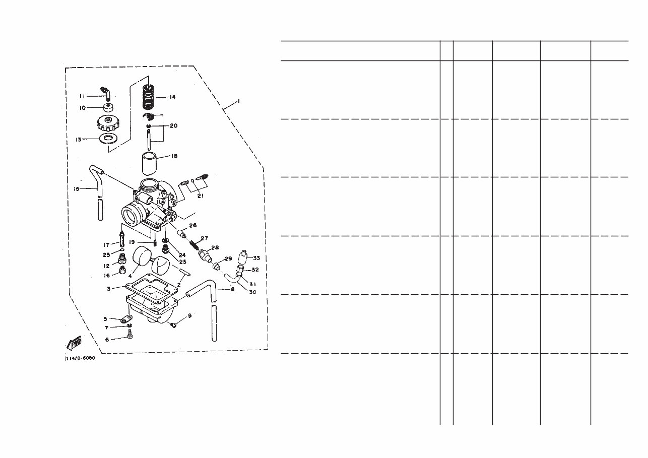
1 4TL141010100 CAR BORETTOR ASSY. 1 1L5650000 #
2 127141860000 PIN FLOAT 1 1L1560001 127141860000 #
3 1L1560002X00 GASKET FLOAT CHAMBER 1 1L1560002 1L1560002X00 Δ
4 1L1560300X00 FLOAT 1 1L1560300 1L1560300X00 Δ
5 1L1560004X00 PLATE 1 1L1560004 1L1560004X00 #
6 9760N0411600 CRP HD SCREW W / WASHER 4 000034211 #
7 929900410000 SPRING WASHER 4 000005102 #
8 1V3141960000 PIPE 1 1L1560006 #
9 12R141910000 PLUG, DRAIN 1 1L1560007 #
10 1M1141690000 CAP 1 1L5560001 #
11 1L5662500X00 CABLE ADJ.SCREW SET 1 1L5662500 1L5662500X00 #
12 1L1560009X00 HOLDER 1 1L1560009 1L1560009X00 #
13 1L1560010X00 PACKING 1 1L1560010 1L1560010X00 Δ
14 4TL141310000 SPRING THROTTLE VALVE 1 1L5560002 #
15 3L7141970000 PIPE 1 1L5560003 #
16 1L5560006X00 JET MAIN 1 1L5560006 1L5560006X00 #
17 4TL141412800 NOZZLE MAIN 1 1L5560004 #
18 304141122000 VALVE, THROTTLE 1 1 1L1560015 #
19 1L5560005X00 JET PILOT20 1 1L5560005 1L5560005X00 #
20 4TL149030000 NEEDLE SET 1 1L5662600 #
21 3MB141040000 AIR SCREW SET 1 1L5662700 #
22 1L5662400X00 THROTTLE SCREW SET 1 1L5662400 1L5662400X00 #
23 31J141072000 NEEDLE VALVE SET 1 1L1560500 #
24 36LE41950000 WASHER VALVE SEAT 1 1L1560020 Δ
25 214141470000 O.RING 1 1L1560024
26 1L5650003X00 PLUNGER STARTER 1 1L5650003 1L5650003X00 #
27 509141350000 PLUNGER SPRING 1 1L5650004 1L5650004X00 #
FIG. 5 CARBURETOR
You're Reading a Preview
What's Included?
Fast Download Speeds
Online & Offline Access
Access PDF Contents & Bookmarks
Full Search Facility
Print one or all pages of your manual
$27.99
Viewed 31 Times Today


Secure transaction
What's Included?
Fast Download Speeds
Online & Offline Access
Access PDF Contents & Bookmarks
Full Search Facility
Print one or all pages of your manual
$27.99
If you are in need of a comprehensive parts catalog for the Yamaha RX135, our digital manual is an invaluable resource. Whether you are a professional mechanic or a DIY enthusiast, this manual provides detailed information on every part of the Yamaha RX135. With clear diagrams and precise descriptions, it enables you to identify, locate, and understand the various components of the motorcycle. This manual is available in .PDF format, making it easily accessible for reference whenever necessary. It is an essential tool for anyone involved in the maintenance, repair, or restoration of the Yamaha RX135.


