


RT100A
174
~ .......... · .. .
LIT-11616-07 -35
RT 100A
SERVICE MANUAL
© 1990 by Yamaha Motor Corporation, U.S.A.
1st Edition, January 1990
All rights reserved. Any reprinting or
unauthorized use without the written
permission of Yamaha Motor Corporation,
U.S.A. is expressly prohibited.
Printed in U.S.A.
P/N: LIT-11616-07-35
NOTICE
This manual was by the Yamaha Motor Company primary for use by Yamaha dealers and their
qualified mechanics. It is not possible to put an entire mechanic's education into one manual, so
it is assumed that person using this book to perform maintenance and repairs on Yamaha ma-
chines have a basic understanding of the mechanical concepts and procedures inherent in ma-
chine repair technology. Without such knowledge, attempt repairs or service to this model may
render it unfit to use and/or unsafe.
Yamaha Motor Company, Ltd. is continually striving to improve all models manufactured by
Yamaha. Modifications and significant changes in specifications or procedures will be forwarded
to all Authorized Yamaha dealers and will, there applicable, appear in future editions of this
manual.
TECHNICAL PUBLICATIONS
SERVICE DIVISION
MOTORCYCLE GROUP
YAMAHA MOTOR CO.,L TO.
PARTICULARLY IMPORT ANT INFORMATION
This material is distinguished by the following notation.
A WARNING
CAUTIO,.:
NOTE:
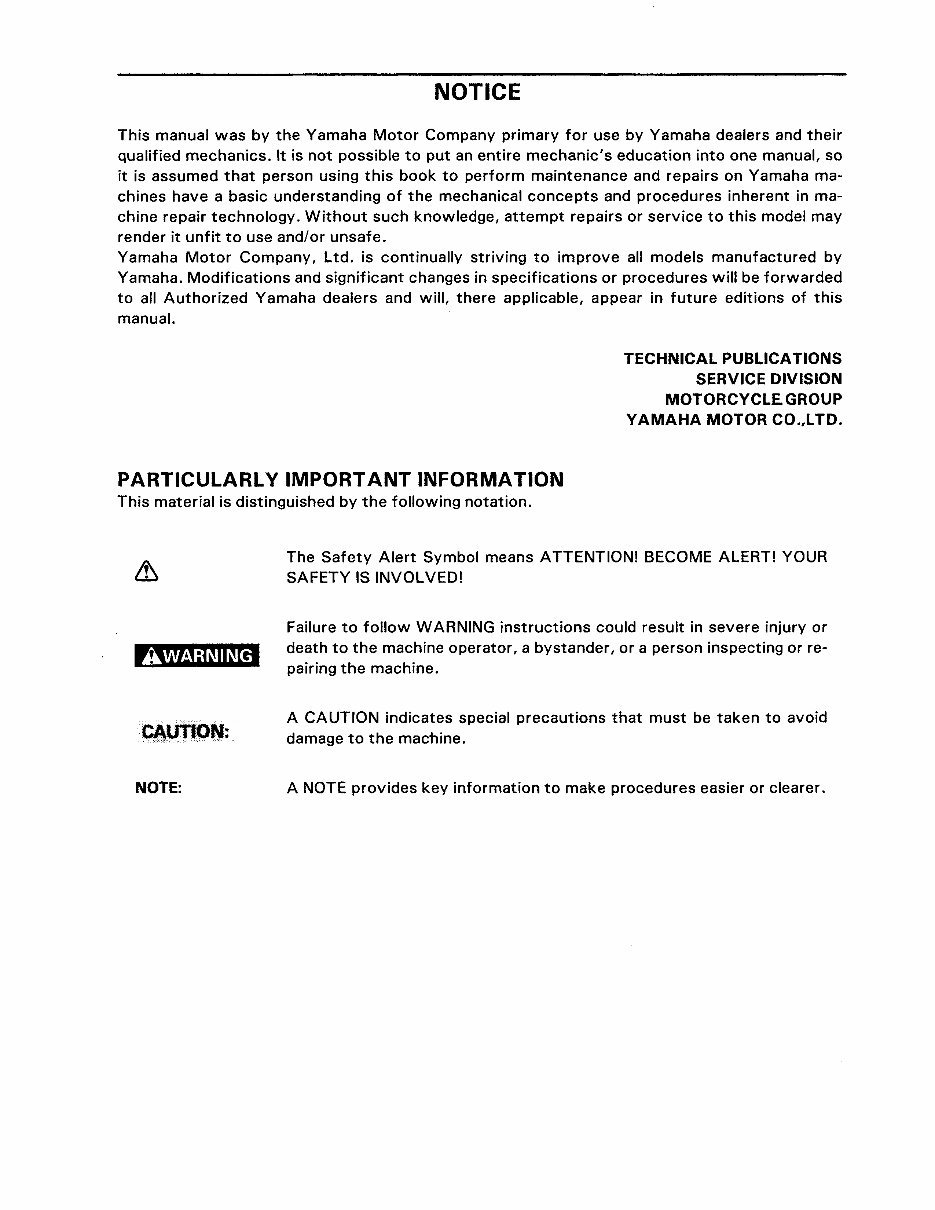
The Safety Alert Symbol means ATTENTION! BECOME ALERT! YOUR
SAFETY IS INVOLVED!
Failure to follow WARNING instructions could result in severe injury or
death to the machine operator, a bystander, or a person inspecting or re-
pairing the machine.
A CAUTION indicates special precautions that must be taken to avoid
damage to the machine.
A NOTE provides key information to make procedures easier or clearer.
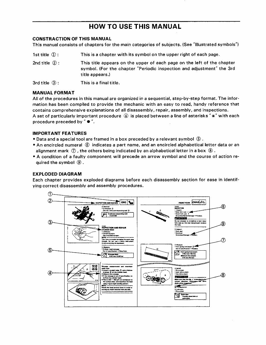
HOW TO USE THIS MANUAL
CONSTRACTION OF THIS MANUAL
This manual consists of chapters for the main categories of subjects. (See "Illustrated symbols")
1st title CD :
2nd title ®:
This is a chapter with its symbol on the upper right of each page.
This title appears on the upper of each page on the left of the chapter
symbol. (For the chapter "Periodic inspection and adjustment" the 3rd
title appears.)
3rd title @: This is a final title.
MANUAL FORMAT
All of the procedures in this manual are organized in a sequential, step-by-step format. The infor-
mation has been compiled to provide the mechanic with an easy to read, handy reference that
contains comprehensive explanations of all disassembly, repair, assembly, and inspections.
A set of particularly important procedure C!> is placed between a line of asterisks .. * .. with each
procedure preceded by " • ...
IMPORTANT FEATURES
• Data and a special tool are framed in a box preceded by a relevant symbol ® .
• An encircled numeral ® indicates a part name, and an encircled alphabetical letter data or an
alignment mark (j) , the others being indicated by an alphabetical letter in a box ® .
• A condition of a faulty component will precede an arrow symbol and the course of action re-
quired the symbol ® .
EXPLODED DIAGRAM
Each chapter provides exploded diagrams before each disassembly section for ease in identif-
ying correct disassembly and assembly procedures.
2.,__.,
•Crlftkt:Mtc <D
liM theC:f .. IIU:-NHf'4Kinetool ~-
li:1 Cr~:-----t--
iNSPECTION AND REPAIR
=--
1.EIImlnM•:
•Cwtlof!MPOM•
liMifOUI'Idllcl~...-r-
..,.,..,..:..:.;::..:.;..:~--
T•• c.,, 10 evoictl.......,.. tl'le "*k-..
ttlfNdi.Donot-· ...... -lnltt~.
AvoiciKYMdlinoW~
w .. ,... _....... - ,_._
-.. .... :
•An.c:t~eeulillll'l,.. (i) Mdltl'llckM-
r--4-~~~~~~•==!:~~-
." m. - ..... ill out of ...ofC.Ciofl, , ..
.-1-thloc.,..,.........,..,
'-----'-----!::.1 •'*-•400-eiOOtritw.t ..... ,on
~~~~:.
___ --::-:::--;,.- ..... ,
,.-:; I '
(~,' • 1 ol
' I
j
-"'
$.1....tlrii:Me:
•Dri¥ec:hlin
CD
®
1~~~~1~1
lsPEcl pf I
@ @
l~g~lnl
I ENG I \,·1
@
®
lcooLI :1: I
lcARslfl
Q)
@
I CHASI r#Y01
1 ELEcl a 1
®
®
~
I~:W~I
?
I
•
@
~
©
~
@
1~1
@
~
®
[8]
®
~
@
® ®
1
1
l
m
m
G)
®
@
@
~E.-
~E.-
~£.-_
@
'
a
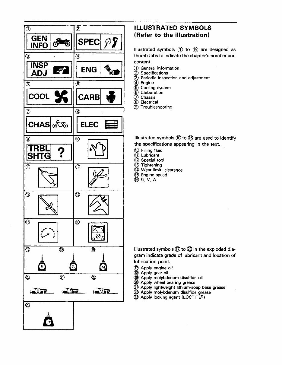
ILLUSTRATED SYMBOLS
(Refer to the illustration)
Illustrated symbols G) to ® are designed as
thumb tabs to indicate the chapter's number and
content.
CD General information
® Specifications
I
Periodic inspection and adjustment
Engine
Cooling system
Carburetion
Q) Chassis
@ Electrical
®Troubleshooting
Illustrated symbols ® to ® are used to identify
the specifications appearing in the text.
I
Filling fluid
Lubricant
Special tool
@ Tightening
@ Wear limit, clearance
® Engine speed
@ fl, V, A
Illustrated symbols @to @ in the exploded dia-
gram indicate grade of lubricant and location of
lubrication point.
@ Apply engine oil
® Apply gear oil
® Apply molybdenum disulfide oil
® Apply wheel bearing grease
® Apply lightweight lithium-soap base grease
@ Apply molybdenum disulfide grease
@Apply locking agent (LOCTITE®)
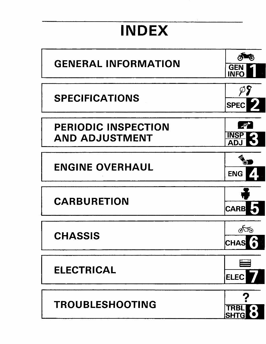
INDEX
GENERAL INFORMATION
SPECIFICATIONS
PERIODIC INSPECTION
AND ADJUSTMENT
ENGINE OVERHAUL
CARBURETION
CHASSIS
ELECTRICAL
TROUBLESHOOTING
SPEC
0
ENG
4
•
?
•
CONTENTS
CHAPTER 1.
GENERAL INFORMATION
MACHINE IDENTIFICATION ............................................ 1-1
VEHICLE IDENTIFICATION NUMBER ................................... 1-1
ENGINE SERIAL NUMBER ........................................... 1-1
IMPORTANT INFORMATION ........................................... 1-2
PREPARATION FOR REMOVAL AND DISASSEMBLY ...................... 1-2
ALL REPLACEMENT PARTS .......................................... 1-3
GASKETS, OIL SEALS, AND 0-RINGS .................................. 1-3
LOCK WASHERS/PLATE AND COTIER PINS ............................ 1-3
BEARINGS AND OIL SEALS .......................................... 1-3
CIRCLIPS ......................................................... 1-4
SPECIAL TOOLS ..................................................... 1-4
FOR TUNE UP ..................................................... 1-4
FOR ENGINE SERVICE .............................................. 1-5
FOR CHASSIS SERVICE ............................................. 1-6
FOR ELECTRICAL COMPONENTS ..................................... 1-6
CHAPTER2.
SPECIFICATIONS
GENERAL SPECIFICATIONS ........................................... 2-1
MAINTENANCE SPECIFICATIONS ...................................... 2-4
ENGINE .......................................................... 2-4
CHASSIS .................................... ; .................... 2-8
ELECTRICAL ..................................................... 2-11
GENERAL TORQUE SPECIFICATIONS .................................. 2-12
DEFINITION OF UNITS ............................................... 2-12
LUBRICATION POINTS AND LUBRICANT TYPE .......................... 2-13
ENGINE ......................................................... 2-13
CHASSIS ........................................................ 2-13
CABLE ROUTING .................................................... 2-14
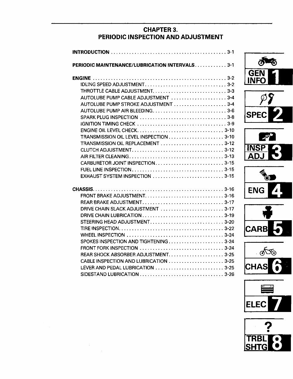
CHAPTER3.
PERIODIC INSPECTION AND ADJUSTMENT
INTRODUCTION ............................................ 3-1
PERIODIC MAINTENANCE/LUBRICATION INTERVALS . ........... 3-1
ENGINE ................................................... 3-2
IDLING SPEED ADJUSTMENT ............................... 3-2
THROTTLE CABLE ADJUSTMENT ............................ 3-3
AUTOLUBE PUMP CABLE ADJUSTMENT ..................... 3-4
AUTOLUBE PUMP STROKE ADJUSTMENT .................... 3-4
AUTOLUBE PUMP AIR BLEEDING ............................ 3-6
SPARK PLUG INSPECTION ................................. 3-8
IGNITION TIMING CHECK .................................. 3-9
ENGINE OIL LEVEL CHECK ................................. 3-10
TRANSMISSION OIL LEVEL INSPECTION ..................... 3-10
TRANSMISSION OIL REPLACEMENT ........................ 3-12
CLUTCH ADJUSTMENT ................................... 3-12
AIR FILTER CLEANING .................................... 3-13
CARBURETOR JOINT INSPECTION .......................... 3-15
FUEL LINE INSPECTION ................................... 3-15
EXHAUST SYSTEM INSPECTION ........................... 3-15
CHASSIS. ................................................. 3-16
FRONT BRAKE ADJUSTMENT .............................. 3-16
REAR BRAKE ADJUSTMENT ............................... 3-17
DRIVE CHAIN SLACK ADJUSTMENT ........................ 3-17
DRIVE CHAIN LUBRICATION ............................... 3-19
STEERING HEAD ADJUSTMENT ............................ 3-20
TIRE INSPECTION ........................................ 3-22
WHEEL INSPECTION ........................... , ......... 3-24
SPOKES INSPECTION AND TIGHTENING ..................... 3-24
FRONT FORK INSPECTION ................................ 3-24
REAR SHOCK ABSORBER ADJUSTMENT ..................... 3-25
CABLE INSPECTION AND LUBRICATION ..................... 3-25
LEVER AND PEDAL LUBRICATION .......................... 3-25
SIDESTAND LUBRICATION ................................ 3-26
~
GEN
INFO
••
SPEC
ENG
ELEC
?
•
2
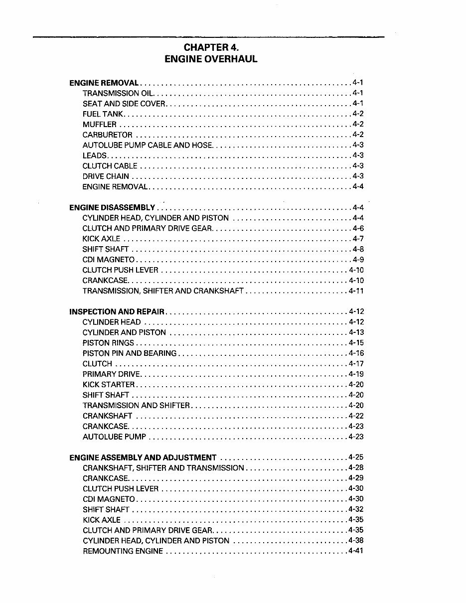
CHAPTER4.
ENGINE OVERHAUL
ENGINE REMOVAL . .................................................. 4-1
TRANSMISSION OIL ............................................... 4-1
SEAT AND SIDE COVER ............................................. 4-1
FUEL TANK ....................................................... 4-2
MUFFLER ........................................................ 4-2
CARBURETOR ................................................... • 4-2
AUTOLUBE PUMP CABLE AND HOSE .................................. 4-3
LEADS ........................................................... 4-3
CLUTCH CABLE ................................................... 4-3
DRIVE CHAIN ..................................................... 4-3
ENGINE REMOVAL. ................................................ 4-4
ENGINE DISASSEMBLY ............................................... 4-4
CYLINDER HEAD, CYLINDER AND PISTON ............................. 4-4
CLUTCH AND PRIMARY DRIVE GEAR. ................................. 4-6
KICK AXLE ....................................................... 4-7
SHIFT SHAFT ..................................................... 4-8
COl MAGNETO .................................................... 4-9
CLUTCH PUSH LEVER ............................................. 4-10
CRANKCASE ..................................................... 4-10
TRANSMISSION, SHIFTER AND CRANKSHAFT ......................... 4-11
INSPECTION AND REPAIR ............................................ 4-12
CYLINDER HEAD ................................................. 4-12
CYLINDER AND PISTON ........................................... 4-13
PISTON RINGS ................................................... 4-15
PISTON PIN AND BEARING ......................................... 4-16
CLUTCH ........................................................ 4-17
PRIMARY DRIVE .................................................. 4-19
KICK STARTER ................................................... 4-20
SHIFT SHAFT .................................................... 4-20
TRANSMISSION AND SHIFTER ...................................... 4-20
CRANKSHAFT ................................................... 4-22
CRANKCASE ..................................................... 4-23
AUTOLUBE PUMP ................................................ 4-23
ENGINE ASSEMBLY AND ADJUSTMENT ............................... 4-25
CRANKSHAFT, SHIFTER AND TRANSMISSION ......................... 4-28
CRANKCASE ..................................................... 4-29
CLUTCH PUSH LEVER ............................................. 4-30
COl MAGNETO ................................................... 4-30
SHIFT SHAFT .................................................... 4-32
KICK AXLE ...................................................... 4-35
CLUTCH AND PRIMARY DRIVE GEAR ................................. 4-35
CYLINDER HEAD, CYLINDER AND PISTON ............................ 4-38
REMOUNTING ENGINE ............................................ 4-41
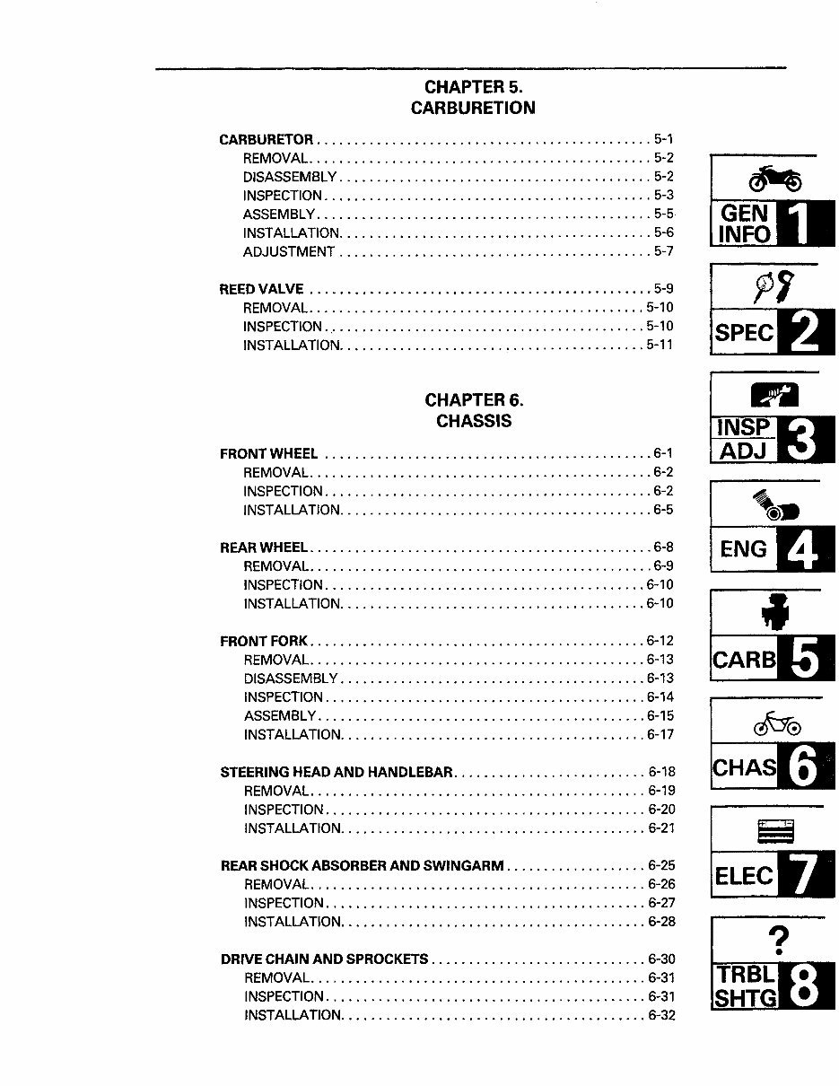
CHAPTERS.
CARBURETION
CARBURETOR . ............................................ 5-1
REMOVAL .............................................. 5-2
DISASSEMBLY .......................................... 5-2
INSPECTION ............................................ 5-3
ASSEMBLY ............................................. 5-5
INSTALLATION .......................................... 5-6
ADJUSTMENT .......................................... 5-7
REED VALVE .............................................. 5-9
REMOVAL ............................................. 5-10
INSPECTION ..· ......................................... 5-10
INSTALLATION ......................................... 5-11
SPEC
CHAPTERS.
CHASSIS
FRONT WHEEL ............................................ 6-1
REMOVAL .............................................. 6-2
INSPECTION ............................................ 6-2
INSTALLATION .......................................... 6-5
0
REAR WHEEL . ............................................. 6-8
REMOVAL .............................................. 6-9 4
ENG
INSPECTION ........................................... 6-10
INSTALLATION ......................................... 6-10
FRONT FORK . ............................................ 6-12
REMOVAL ............................................. 6-13
DISASSEMBLY ......................................... 6-13
INSPECTION ........................................... 6-14
ASSEMBLY ............................................ 6-15
INSTALLATION ......................................... 6-17
STEERING HEAD AND HANDLEBAR .......................... 6-18
REMOVAL ............................................. 6-19
INSPECTION ........................................... 6-20
INSTALLATION ......................................... 6-21
REAR SHOCK ABSORBER AND SWINGARM . .................. 6-25
REMOVAL ............................................. 6-26
INSPECTION ........................................... 6-27
INSTALLATION ......................................... 6-28
?
DRIVE CHAIN AND SPROCKETS ............................. 6-30
•
REMOVAL ............................................. 6-31
INSPECTION ........................................... 6-31
INSTALLATION ......................................... 6-32
You're Reading a Preview
What's Included?
 Lifetime Access
Fast Download Speeds
Online & Offline Access
Access PDF Contents & Bookmarks
Full Search Facility
Print one or all pages of your manual
$39.99
1990-2000 Yamaha RT100 Motorcycle Service & Repair Manual
Viewed 17 Times Today

What's Included?
Lifetime Access
Fast Download Speeds
Online & Offline Access
Access PDF Contents & Bookmarks
Full Search Facility
Print one or all pages of your manual
$39.99

Secure transaction
What's Included?
Lifetime Access
Fast Download Speeds
Online & Offline Access
Access PDF Contents & Bookmarks
Full Search Facility
Print one or all pages of your manual
Description
- This full service and repair manual for the Yamaha RT100 Motorcycle from 1990-2000 is a comprehensive factory workshop manual.
- It is instantly accessible on your computer, tablet, or smartphone without any additional fees or expiration dates.
- Professionally written, it covers all repair, servicing, and troubleshooting procedures with detailed photos and diagrams.
- Used by professional mechanics and technicians, it includes step-by-step instructions and highly detailed exploded diagrams and pictures.
- Yes, you can print out a single page or the entire manual as per your requirement.
- This manual can be used on multiple computers without any limitations or trial periods.
- There are no expiration dates or renewal fees; you can use this manual for life.
- It is fully compatible with Windows and MAC computers.
For more information, please click the button below.


