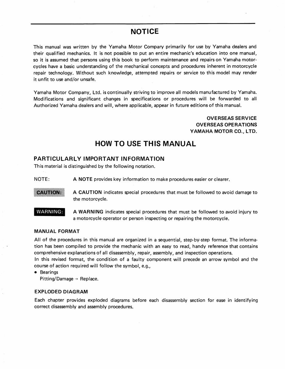
NOTICE This manual was written by the Yamaha Motor Compary primarily for use by Yamaha dealers and their qualified mechanics. It is not possible to put an entire mechanic's education into one manual, so it is assumed that persons using this book to perform maintenance and repairs on Yamaha motor- cycles have a basic understanding of the mechanical concepts and procedures inherent in motorcycle repair technology. Without such knowledge, attempted repairs or service to this model may render it unfit to use and/or unsafe. Yamaha Motor Company, Ltd. is continually striving to improve all models manufactured by Yamaha. Modifications and significant changes in specifications or procedures will be forwarded to all Authorized Yamaha dealers and will, where applicable, appear in future editions of this manual. OVERSEAS SERVI CE OVERSEAS OPERATI ONS Y A M A H A MOTOR CO., LTD. HOW TO USE THIS MANUAL PARTICULARLY IMPORTANT INFORMATION This material is distinguished by the following notation. NOTE: A NOTE provides key information to make procedures easier or clearer. CAUTION: A CAUTION indicates special procedures that must be followed to avoid damage to the motorcycle. ^^^^^^m A WARNING indicates special procedures that must be followed to avoid injury to a motorcycle operator or person inspecting or repairing the motorcycle. MANUAL FORMAT All of the procedures in this manual are organized in a sequential, step-by-step format. The informa- tion has been compiled to provide the mechanic with an easy to read, handy reference that contains comprehensive explanations of all disassembly, repair, assembly, and inspection operations. In this revised format, the condition of a faulty component will precede an arrow symbol and the course of action required will follow the symbol, e.g., • Bearings Pitting/Damage -> Replace. EXPLODED D IA GR A M Each chapter provides exploded diagrams before each disassembly section for ease in identifying correct disassembly and assembly procedures.
INDEX GENERAL INFORMATION 1 PERIODIC INSPECTIONS 1 | AND ADJUSTMENTS ENGINE OVERHAUL CARBURETION CHASSIS ELECTRICAL APPENDICES
CHAPTER 1 . GENERAL I NFORMATION SCOOTER IDENTIFICATION 1-1 VEHICLE IDENTIFICATION NUMBER 1-1 ENGINE SERIAL NUMBER 1-1 IMPORTANT INFORMATION 1-2 ALL REPLACEMENT PARTS 1-2 GASKETS, OIL SEALS, AND O-RINGS 1-2 LOCK WASHERS/PLATES AND COTTER PINS. . 1-2 BEARINGS AND OILSEALS 1-2 CIRCLIPS 1-3 SPECIAL TOOLS 1-3 FOR TUNE-UP 1-3 FOR ENGINE SERVICE 1-4 FOR CHASSIS SERVICE 1-6 FOR ELECTRICAL COMPONENTS 1-6
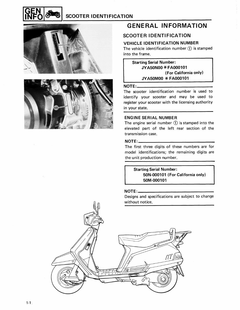
SCOOTER IDENTIFICATION GENERAL INFORMATION SCOOTER IDENTIFICATION VEHI CLE IDEN T IFI C A T ION NUMBER The vehicle identification number 0 is stamped into the frame. Starting Serial Number: JYA50 N00 *F A 000 1 0 1 (For Cali forni a only) JYA50M00 * FA000 1 0 1 NOTE: The scooter identification number is used to identify your scooter and may be used to register your scooter with the licensing authority in your state. ENGINE SERIAL NUMBER The engine serial number 0 is stamped into the elevated part of the left rear section of the transmission case. NOTE: The first three digits of these numbers are for model identifications; the remaining digits are the unit production number. Starting Serial Number: 50N-000101 (For California only) 50M- 000101 NOTE: — Designs and specifications are subject to change without notice.
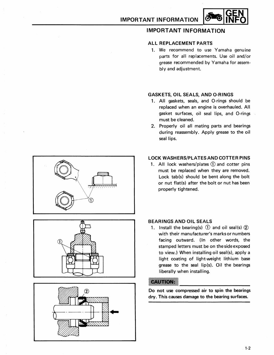
IMPORTANT INFORMATION IMPORTANT INFORMATION ALL REPLACEMENT PARTS 1. We recommend to use Yamaha genuine parts for all replacements. Use oil and/or grease recommended by Yamaha for assem- bly and adjustment. GASKETS, OIL SEALS, AND O-RINGS 1 . All gaskets, seals, and O-rings should be replaced when an engine is overhauled. All gasket surfaces, oil seal lips, and O-rings must be cleaned. 2. Properly oil all mating parts and bearings during reassembly. Apply grease to the oil seal lips. LOCK WASHERS/ PLATES AND COTTER PINS 1. All lock washers/plates ® and cotter pins must be replaced when they are removed. Lock tab(s) should be bent along the bolt or nut flat(s) after the bolt or nut has been properly tightened. BEARINGS AND OIL SEALS 1 . Install the bearing(s) ® and oil seal(s) (2) with their manufacturer's marks or numbers facing outward. (In other words, the stamped letters must be on the side exposed to view.) When installing oil seal(s), apply a light coating of light-weight lithium base grease to the seal lip(s). Oil the bearings liberally when installing. mntmt Do not us e compressed air t o spin the bearings dry. This c aus e s damage t o the bearing surfaces. 1-2
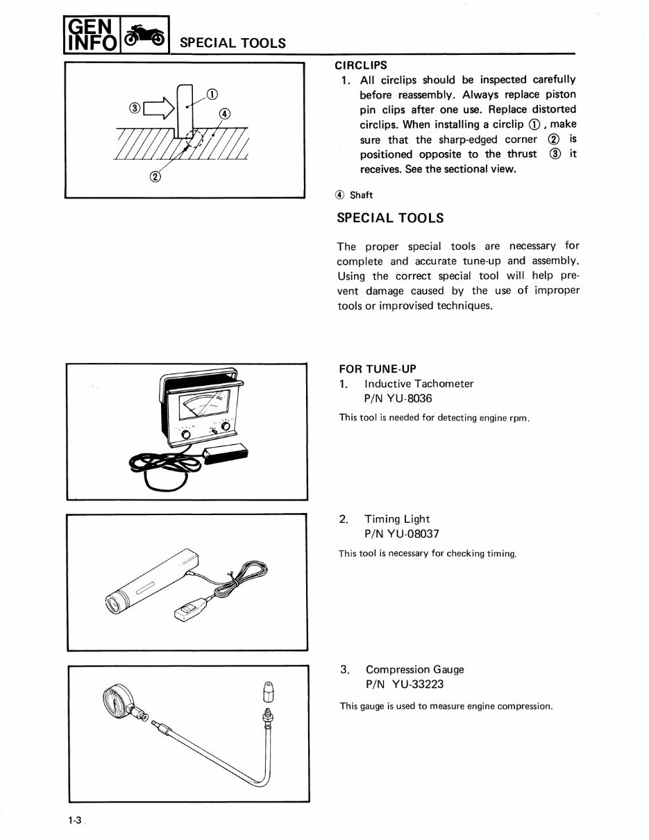
SPECIAL TOOLS CIRCLIPS 1 . All circlips should be inspected carefully before reassembly. Always replace piston pin clips after one use. Replace distorted circlips. When installing a circlip ® , make sure that the sharp-edged corner (2) i s positioned opposite t o the thrust (3) it receives. See the sectional view. ® Shaft SPECI AL TOOLS The proper special tools are necessary for complete and accurate tune-up and assembly. Using the correct special tool will help pre- vent damage caused by the use of improper tools or improvised techniques. FOR TUNE- UP 1. Inductive Tachometer P/N YU-8036 This tool is needed for detecting engine rpm. 2. Timing Light P/N YU-08037 This tool is necessary for checking timing. 3. Compression Gauge P/N YU-33223 This gauge is used to measure engine compression. 1-3
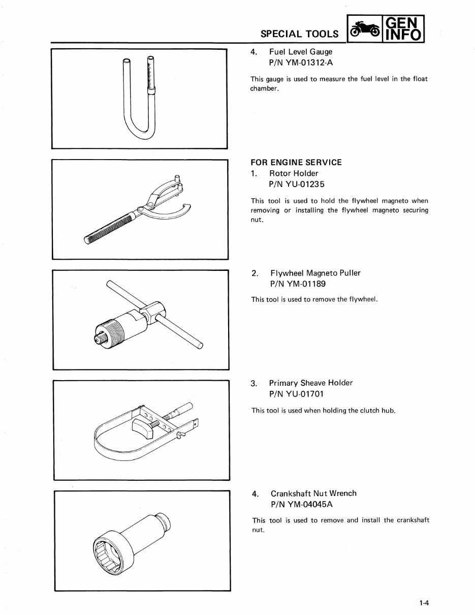
SPECIAL TOOLS 4. Fuel Level Gauge P/N YM- 01312-A This gauge is used to measure the fuel level in the float chamber. FOR ENGINE SERVI CE 1. Rot or Holder P/N YU- 01 23 5 This tool is used to hold the flywheel magneto when removing or installing the flywheel magneto securing nut. 2. Flywheel Magneto Puller P/N YM-01189 This tool is used to remove the flywheel. 3. Primary Sheave Holder P/N YU-01701 This tool is used when holding the clutch hub. 4. Crankshaft Nut Wrench P/N YM-04045A This tool is used to remove and install the crankshaft nut. 1-4
This comprehensive service manual is designed for the Riva XC125 models manufactured between 1985 and 2001. It is a valuable resource for both professional mechanics and DIY enthusiasts, covering a wide range of repair topics including general information, periodic maintenance, fuel system, cooling system, engine top end, engine lubrication system, engine removal/installation, crankshaft/crankcase, transmission, wheels/tires, final drive, brakes, suspension, steering, frame, and electrical system.
The manual includes detailed diagrams, illustrations, photos, exploded views, and step-by-step instructions for diagnostics and similar topics. With all pages being printable, it offers convenience and cost savings on postage and packaging. This manual empowers DIY mechanics to handle maintenance tasks themselves, reducing reliance on dealer labor and associated costs.