EAS00001 YP400 2004-2009 SERVICE MANUAL Yamaha Motor Corporation, U.S.A. First edition, June 2004 All rights reserved. Any reproduction or unauthorized use without the written permission of Yamaha Motor Corporation, U.S.A. is expressly prohibited. Printed in U.S.A.
EAS00003 NOTICE This manual was produced by the Yamaha Motor Company, Ltd. primarily for use by Yamaha deal- ers and their qualified mechanics. It is not possible to include all the knowledge of a mechanic in one manual. Therefore, anyone who uses this book to perform maintenance and repairs on Yamaha vehicles should have a basic understanding of mechanics and the techniques to repair these types of vehicles. Repair and maintenance work attempted by anyone without this knowledge is likely to render the vehicle unsafe and unfit for use. This model has been designed and manufactured to perform within certain specifications in regard to performance and emissions. Proper service with the correct tools is necessary to ensure that the vehicle will operate as designed. If there is any question about a service procedure, it is imperative that you contact a Yamaha dealer for any service information changes that apply to this model. This policy is intended to provide the customer with the most satisfaction from his vehicle and to conform to federal environmental quality objectives. Yamaha Motor Company, Ltd. is continually striving to improve all of its models. Modifications and significant changes in specifications or procedures will be forwarded to all authorized Yamaha deal- ers and will appear in future editions of this manual where applicable. NOTE: _ • This Service Manual contains information regarding periodic maintenance to the emission control system. Please read this material carefully. • Designs and specifications are subject to change without notice. EAS00005 IMPORTANT MANUAL INFORMATION Particularly important information is distinguished in this manual by the following. The Safety Alert Symbol means ATTENTION! BECOME ALERT! YOUR SAFETY IS INVOLVED! Failure to follow WARNING instructions could result in severe injury or death to the scooter operator, a bystander or a person checking or repairing the scooter. A CAUTION indicates special precautions that must be taken to avoid damage to the scooter. A NOTE provides key information to make procedures easier or clearer. WARNING CAUTION: NOTE:
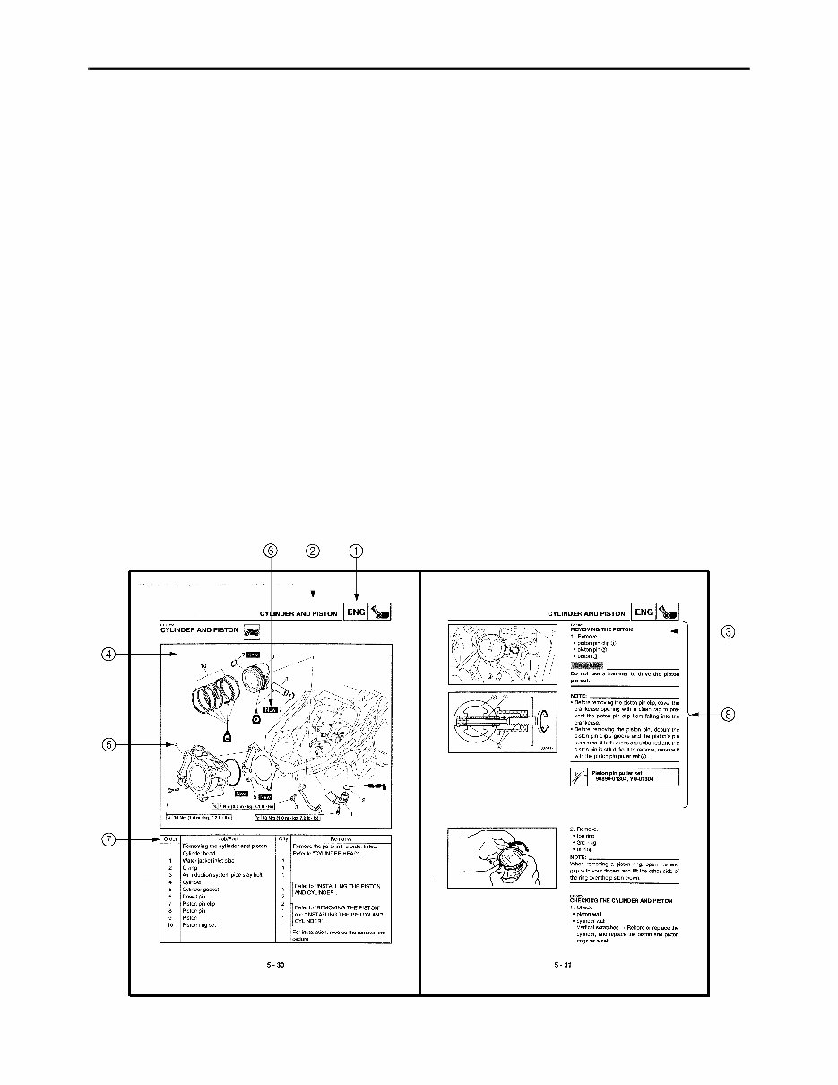
EAS00007 HOW TO USE THIS MANUAL This manual is intended as a handy, easy-to-read reference book for the mechanic. Comprehensive explanations of all installation, removal, disassembly, assembly, repair and check procedures are laid out with the individual steps in sequential order. 1 The manual is divided into chapters. An abbreviation and symbol in the upper right corner of each page indicate the current chapter. Refer to “SYMBOLS”. 2 Each chapter is divided into sections. The current section title is shown at the top of each page, except in Chapter 3 (“PERIODIC CHECKS AND ADJUSTMENTS”), where the sub-section title(s) appears. 3 Sub-section titles appear in smaller print than the section title. 4 To help identify parts and clarify procedure steps, there are exploded diagrams at the start of each removal and disassembly section. 5 Numbers are given in the order of the jobs in the exploded diagram. A circled number indicates a disassembly step. 6 Symbols indicate parts to be lubricated or replaced. Refer to “SYMBOLS”. 7 A job instruction chart accompanies the exploded diagram, providing the order of jobs, names of parts, notes in jobs, etc. 8 Jobs requiring more information (such as special tools and technical data) are described sequen- tially.
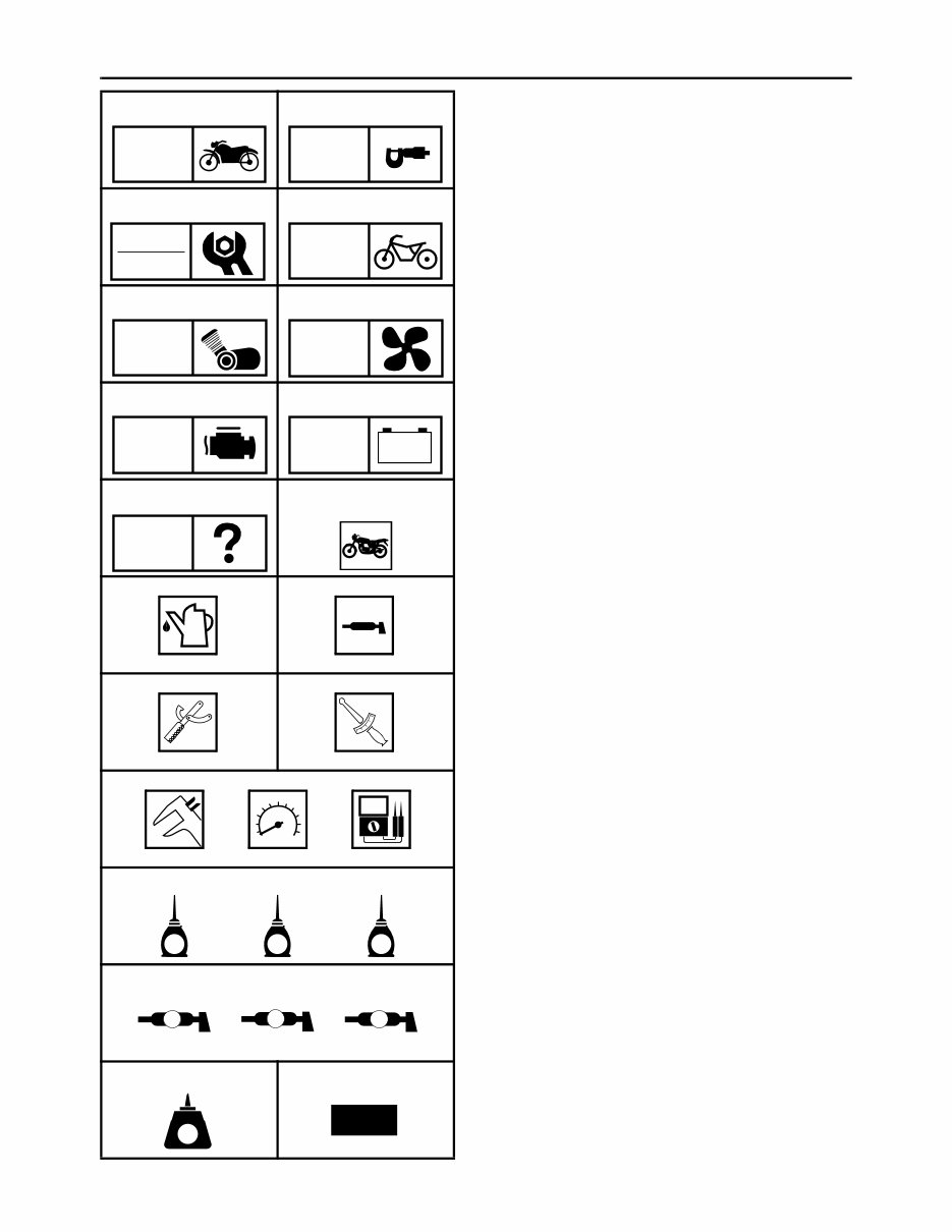
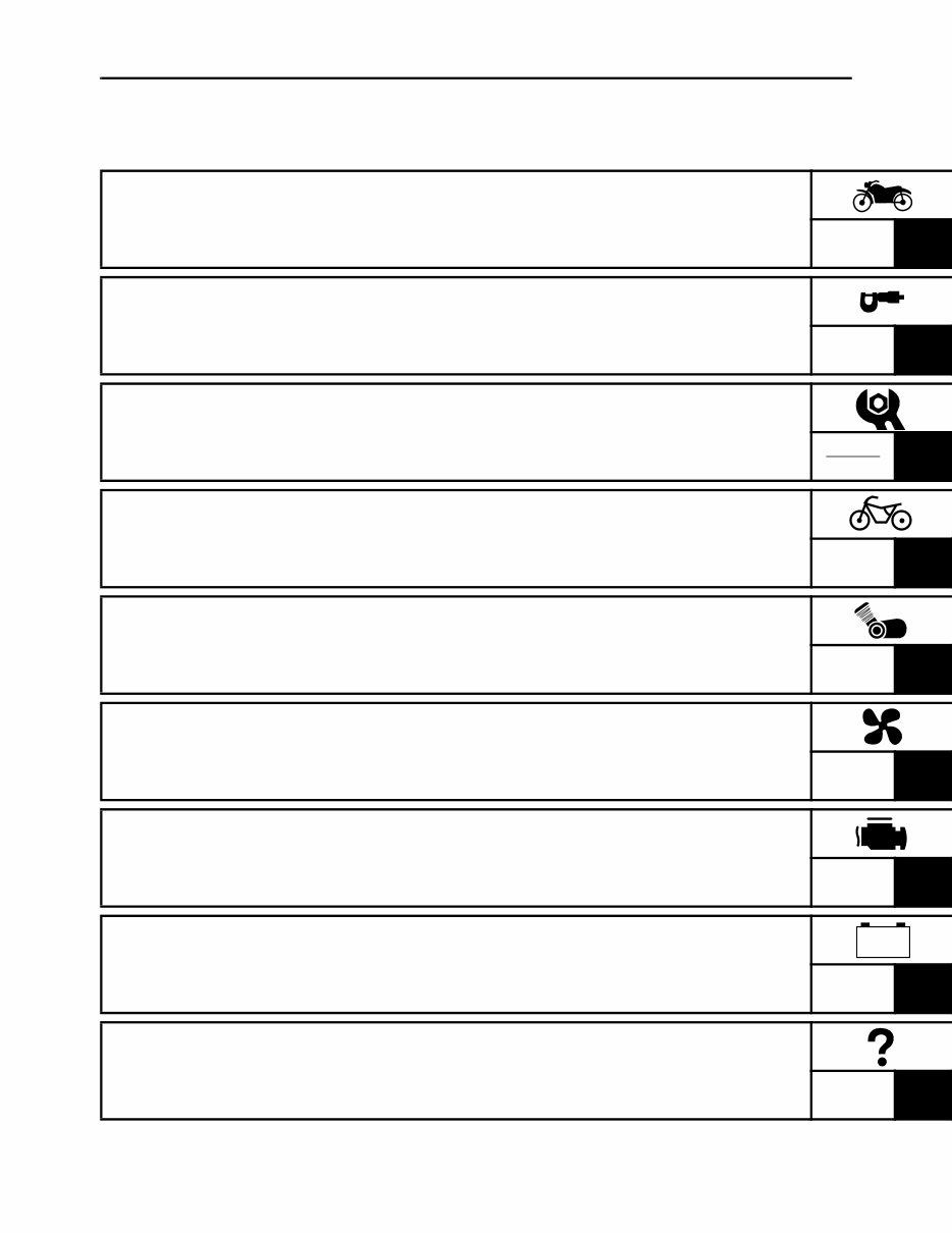
EAS00008 SYMBOLS The following symbols are not relevant to every vehicle. Symbols 1 to 9 indicate the subject of each chapter. 1 General information 2 Specifications 3 Periodic checks and adjustments 4 Chassis 5 Engine 6 Cooling system 7 Fuel injection system 8 Electrical system 9 Troubleshooting Symbols 0 to G indicate the following. 0 Serviceable with engine mounted A Filling fluid B Lubricant C Special tool D Tightening torque E Wear limit, clearance F Engine speed G Electrical data Symbols H to M in the exploded diagrams indicate the types of lubricants and lubrication points. H Engine oil I Gear oil J Molybdenum-disulfide oil K Wheel-bearing grease L Lithium-soap-based grease M Molybdenum-disulfide grease Symbols N to O in the exploded diagrams indicate the following. N Apply locking agent (LOCTITE ® ) O Replace the part 1 2 3 4 5 6 7 8 9 0 A B C D E F G H I J K L M N O GEN INFO SPEC CHK ADJ CHAS ENG COOL FI – + ELEC TRBL SHTG T R . . E G M B LS M LT New
EAS00010 TABLE OF CONTENTS GENERAL INFORMATION GEN INFO 1 SPECIFICATIONS SPEC 2 PERIODIC CHECKS AND ADJUSTMENTS CHK ADJ 3 CHASSIS CHAS 4 ENGINE ENG 5 COOLING SYSTEM COOL 6 FUEL INJECTION SYSTEM FI 7 ELECTRICAL SYSTEM ELEC 8 TROUBLESHOOTING TRBL SHTG 9 – +
CONTENTS CHAPTER 1 GENERAL INFORMATION SCOOTER IDENTIFICATION.......................................................................... 1-1 VEHICLE IDENTIFICATION NUMBER ..................................................... 1-1 MODEL LABEL.......................................................................................... 1-1 FEATURES ...................................................................................................... 1-2 OUTLINE OF THE FI SYSTEM ................................................................. 1-2 FI SYSTEM................................................................................................ 1-3 INSTRUMENT FUNCTIONS ..................................................................... 1-4 IMPORTANT INFORMATION ....................................................................... 1-10 PREPARATION FOR REMOVAL AND DISASSEMBLY......................... 1-10 REPLACEMENT PARTS......................................................................... 1-10 GASKETS, OIL SEALS AND O-RINGS .................................................. 1-10 LOCK WASHERS/PLATES AND COTTER PINS ................................... 1-11 BEARINGS AND OIL SEALS .................................................................. 1-11 CIRCLIPS ................................................................................................ 1-11 CHECKING THE CONNECTIONS ................................................................ 1-12 SPECIAL TOOLS .......................................................................................... 1-13 CHAPTER 2 SPECIFICATIONS GENERAL SPECIFICATIONS ........................................................................ 2-1 ENGINE SPECIFICATIONS ........................................................................... 2-2 CHASSIS SPECIFICATIONS ........................................................................ 2-10 ELECTRICAL SPECIFICATIONS ................................................................. 2-14 CONVERSION TABLE .................................................................................. 2-17 GENERAL TIGHTENING TORQUE SPECIFICATIONS ............................... 2-17
TIGHTENING TORQUES .............................................................................. 2-18 ENGINE TIGHTENING TORQUES ......................................................... 2-18 CHASSIS TIGHTENING TORQUES ....................................................... 2-21 LUBRICATION POINTS AND LUBRICANT TYPES .................................... 2-23 ENGINE LUBRICATION POINTS AND LUBRICANT TYPES ................ 2-23 CHASSIS LUBRICATION POINTS AND LUBRICANT TYPES ............. 2-25 COOLING SYSTEM DIAGRAMS .................................................................. 2-26 CABLE ROUTING ......................................................................................... 2-28 CHAPTER 3 PERIODIC CHECKS AND ADJUSTMENTS INTRODUCTION.............................................................................................. 3-1 PERIODIC MAINTENANCE CHART FOR THE EMISSION CONTROL SYSTEM........................................................................................ 3-1 GENERAL MAINTENANCE AND LUBRICATION CHART ............................ 3-2 COWLING AND COVERS ............................................................................... 3-4 PASSENGER SEAT AND SIDE COVERS................................................ 3-4 RIDER SEAT AND STORAGE BOX ......................................................... 3-5 SIDE COVER MOULDINGS AND FOOTREST BOARDS ........................ 3-7 FRONT COWLING .................................................................................... 3-8 AIR FILTER CASES ...................................................................................... 3-10
ENGINE ......................................................................................................... 3-11 ADJUSTING THE VALVE CLEARANCE ................................................ 3-11 ADJUSTING THE EXHAUST GAS VOLUME ......................................... 3-16 CHECKING THE ENGINE IDLING SPEED ............................................ 3-17 ADJUSTING THE THROTTLE CABLE FREE PLAY .............................. 3-18 CHECKING THE SPARK PLUG ............................................................. 3-18 CHECKING THE IGNITION TIMING ....................................................... 3-20 MEASURING THE COMPRESSION PRESSURE .................................. 3-21 CHECKING THE ENGINE OIL LEVEL.................................................... 3-23 CHANGING THE ENGINE OIL ............................................................... 3-24 CHANGING THE TRANSMISSION OIL .................................................. 3-27 REPLACING THE AIR FILTER ELEMENTS ........................................... 3-28 CLEANING THE V-BELT CASE AIR FILTER ELEMENT ....................... 3-29 CHECKING THE THROTTLE BODY JOINT AND INTAKE MANIFOLD ............................................................................... 3-30 CHECKING THE FUEL HOSE ................................................................ 3-30 CHECKING THE BREATHER HOSES ................................................... 3-31 CHECKING THE EXHAUST SYSTEM.................................................... 3-32 CHECKING THE COOLANT LEVEL ....................................................... 3-32 CHECKING THE COOLING SYSTEM .................................................... 3-33 CHANGING THE COOLANT................................................................... 3-34 CHASSIS ....................................................................................................... 3-37 ADJUSTING THE REAR BRAKE LOCK LEVER CABLE ....................... 3-37 CHECKING THE BRAKE FLUID LEVEL................................................. 3-38 CHECKING THE FRONT AND REAR BRAKE PADS ............................ 3-39 CHECKING THE FRONT AND REAR BRAKE HOSES.......................... 3-39 BLEEDING THE HYDRAULIC BRAKE SYSTEM ................................... 3-40 CHECKING AND ADJUSTING THE STEERING HEAD ......................... 3-41 CHECKING THE FRONT FORK ............................................................. 3-43 CHECKING THE TIRES .......................................................................... 3-44 CHECKING THE WHEELS ..................................................................... 3-47 CHECKING AND LUBRICATING THE CABLES .................................... 3-47 LUBRICATING THE LEVERS ................................................................. 3-48 LUBRICATING THE SIDESTAND........................................................... 3-48 LUBRICATING THE CENTERSTAND .................................................... 3-48 ELECTRICAL SYSTEM................................................................................. 3-49 CHECKING AND CHARGING THE BATTERY ....................................... 3-49 CHECKING THE FUSES ........................................................................ 3-54 REPLACING THE HEADLIGHT BULBS ................................................. 3-56 ADJUSTING THE HEADLIGHT BEAMS ................................................. 3-58
CHAPTER 4 CHASSIS FRONT WHEEL AND BRAKE DISC............................................................... 4-1 REMOVING THE FRONT WHEEL............................................................ 4-3 CHECKING THE FRONT WHEEL ............................................................ 4-3 CHECKING THE BRAKE DISCS .............................................................. 4-4 INSTALLING THE FRONT WHEEL .......................................................... 4-6 ADJUSTING THE FRONT WHEEL STATIC BALANCE ........................... 4-7 REAR WHEEL AND BRAKE DISC ................................................................. 4-9 REMOVING THE REAR WHEEL ............................................................ 4-10 CHECKING THE REAR WHEEL............................................................. 4-10 ADJUSTING THE REAR WHEEL STATIC BALANCE............................ 4-10 FRONT AND REAR BRAKES....................................................................... 4-11 FRONT BRAKE PADS ............................................................................ 4-11 REAR BRAKE PADS............................................................................... 4-12 REPLACING THE FRONT BRAKE PADS .............................................. 4-13 REPLACING THE REAR BRAKE PADS................................................. 4-15 FRONT BRAKE MASTER CYLINDER .................................................... 4-18 REAR BRAKE MASTER CYLINDER ...................................................... 4-21 DISASSEMBLING THE FRONT BRAKE MASTER CYLINDER ............. 4-24 DISASSEMBLING THE REAR BRAKE MASTER CYLINDER................ 4-24 CHECKING THE FRONT AND REAR BRAKE MASTER CYLINDERS ........................................................................... 4-25 ASSEMBLING AND INSTALLING THE FRONT BRAKE MASTER CYLINDER ............................................................................. 4-26 ASSEMBLING AND INSTALLING THE REAR BRAKE MASTER CYLINDER ............................................................................. 4-28 FRONT BRAKE CALIPER....................................................................... 4-31 REAR BRAKE CALIPER ......................................................................... 4-33 DISASSEMBLING THE FRONT BRAKE CALIPER ................................ 4-36 DISASSEMBLING THE REAR BRAKE CALIPER .................................. 4-36 CHECKING THE FRONT AND REAR BRAKE CALIPERS .................... 4-37 ASSEMBLING AND INSTALLING THE FRONT BRAKE CALIPER ....... 4-39 ASSEMBLING AND INSTALLING THE REAR BRAKE CALIPER .......... 4-41 FRONT FORK................................................................................................ 4-44 REMOVING THE FRONT FORK LEGS .................................................. 4-48 DISASSEMBLING THE FRONT FORK LEGS ........................................ 4-48 CHECKING THE FRONT FORK LEGS .................................................. 4-50 ASSEMBLING THE FRONT FORK LEGS .............................................. 4-50 INSTALLING THE FRONT FORK LEGS ................................................ 4-53 HANDLEBAR ................................................................................................ 4-54 REMOVING THE HANDLEBAR .............................................................. 4-56 CHECKING THE HANDLEBAR .............................................................. 4-56 INSTALLING THE HANDLEBAR ............................................................ 4-56
This complete workshop and repair manual for the YAMAHA MAJESTY 400 YP400T YP400V YP400W covers all models for the years 2005-2007 and includes all engine types. It is a professional quality manual with in-depth service and repair information, making it useful for both professional mechanics and DIY enthusiasts.
The manual provides easy-to-follow, step-by-step instructions, pictures, and wiring diagrams for all repair areas, making every repair job easy to do. It covers all servicing and repair jobs, including routine maintenance, and is compatible with Win/MAC/Linux systems. The manual is instantly accessible upon receipt of payment, with no shipping costs or waiting for delivery.
With detailed repair procedures and comprehensive information, this manual will help users better understand all parts and repair procedures, enabling them to easily perform their own servicing, maintenance, and repairs. It is designed for easy use on PC, tablet, or laptop, and is suitable for users of all skill levels.
Full professional quality in-depth service and repair manual
Step-by-step instructions, pictures, and wiring diagrams
Covers all servicing and repair jobs, including routine maintenance
Compatible with Win/MAC/Linux systems
Instant access with no shipping costs
Easy to use on PC, tablet, or laptop
Save money by performing repairs yourself using the information and knowledge contained in this manual. It covers all aspects of service, repair, and maintenance, helping users save thousands of dollars by avoiding expensive mechanic fees. The manual is designed for easy use and is instantly accessible upon payment, making it convenient for users to start their repairs today.









 Lifetime Access




