

YAMAHA FZ6S FZ6N Bike Workshop Service Repair Manual
What's Included?
Fast Download Speeds
Offline Viewing
Access Contents & Bookmarks
Full Search Facility
Print one or all pages of your manual

The European version of the Yamaha FZ6 has running lights mounted in small 'pods'
in the corners of the headlights. For whatever reason, these pod lights never made
it into the North American version. Well, I wasn't going to be satisfied with that and
decided to install my own.
This how-to is adapted from the one published as an article in the motorcycling
section on my website (mastermind.mine.nu). Direct link to how-to:
http://mastermind.mine.nu/index.php...id=44&Itemid=80
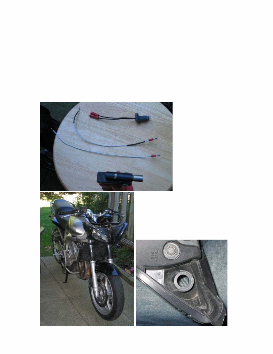
Parts you need:
• 2 x ’03 Yamaha R1 Pod Light Sockets (www.bikebandit.com part #1486440-
001, Yamaha Part # 5PW-84312-00-00)
• 2 x 194 bulbs. I used LED bulbs (readily available on e-bay).
• Wire connectors; 4 female/male pairs (so that the lights can be disconnected
easily)
• Automotive wire (I used 20ga)
• Electrical tape
Tools you need:
• Drill and/or dremel (to create holes for the light sockets)
• Soldering iron and soldering grease
• Crimping tool
• Misc tools (to remove the fairing as well as headlight assembly)
It is not necessary to remove the fairing, mirrors, or the windscreen
Step 1: Remove fairing and headlight assembly
Check your shop manual if you’re not familiar with how to do anything in this step.
• Remove the windscreen
• Remove the inner fairing panels
• Disconnect the turn signals (take note of what the turn signals are connected
to, that’s where we’ll be splicing into)
• Remove the upper fairing and headlight assembly.
Tip: If you’ve never done this, there’s one extra (undocumented?) screw that
attaches the upper fairing to the headlight assembly. You can’t get to this
screw unless you remove the headlight assembly from the bracket and tilt it
down, the screw is under the “bubble” portion of the upper fairing (See Image
1).
Image 1 (pod_mod_1.jpg): The FZ6 is almost completely stripped of its front fairing
and headlight assembly. The headlight assembly is about to be removed before
moving on top Step 2.
Step 2: Drilling holes for bulb sockets
I removed the inner pieces of the fairing--the ones you have to remove to get the
tank off. I then simply used a Uni-Bit to drill a 9/16" hole in each side for the
sockets. I also used shrink wrap on all wiring. It took less than 1 hour and looks like
a factory install. The only other thing I had to remove was the turn signalks to get
the wiring done properly (it made soldering and shrink wrapping much easier).
Do this step nice and easy as the holes should be centred in the pods and the right
size to fit your bulb sockets. I did this part by first grinding off the little nubs of
plastic that were sticking out in the middle of the back of the pod. I then drilled a
pilot hole with a drill, and used a bit to increase the hole to the desired size. There
are many ways of doing this step, just make sure you do a nice clean job. After all,
we’re going for a factory look here (See Image 2)
Image 2 (pod_mod_2.jpg): At the end of Step 2, you should have two holes roughly
this size. Rembember to leave the hole small enough so that the bulb socket is a
reasonably snug fit.
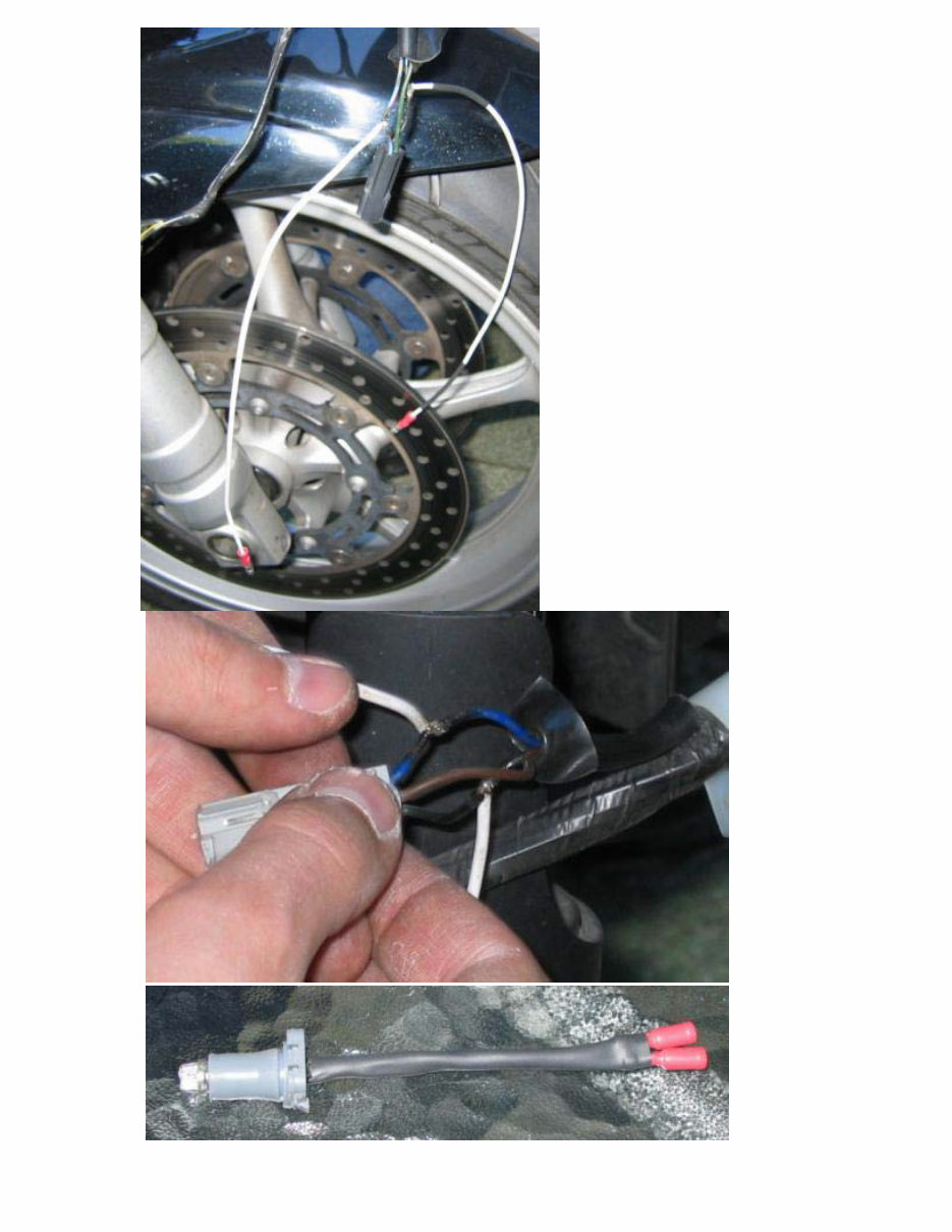
Step 3: Wiring up sockets.
• Cut off the connectors that are attached to the R1 bulb sockets. Remove
about ¼” of insulation from the ends of each wire.
• Attach and crimp a female connector to the end of each wire (See Image 3)
Image 3 (pod_mod_3.jpg): Bulb socket fully wired up. Also in this picture, two wires
ready to be spliced into the wiring harness in Step 4.
Attached Thumbnails

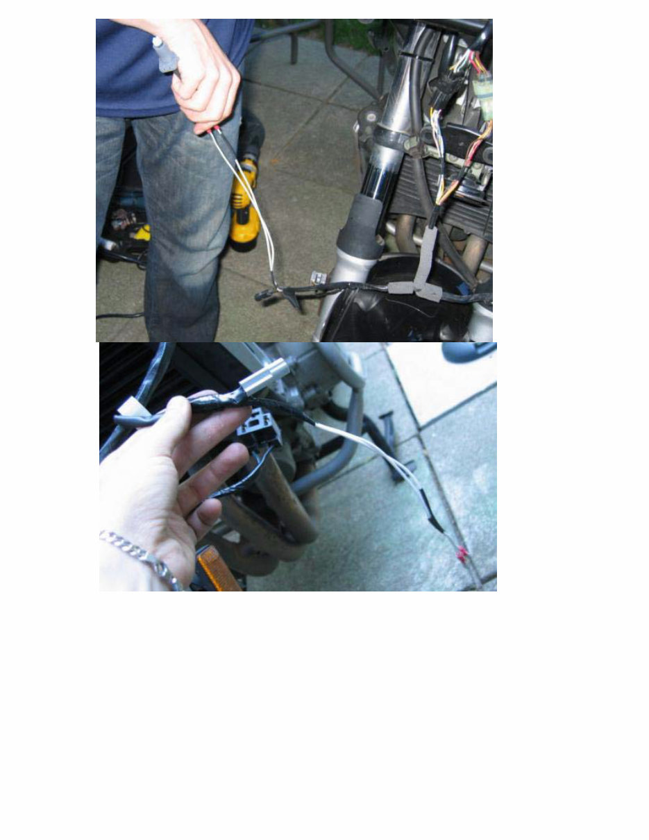
Step 4: Splicing into turn signal wiring
Since our turn signals also function as running lights, we’re going to splice into the
wiring for said turn signals. You’ll find 3 wires, black, blue, and brown. We’ll need the
black (negative) and blue (positive) wires. The brown wire is for the signal part of it,
so we’re not going to use it.
• Cut your wires to length. Each socket will need two wires (so 4 total). I used
a 5-6” length for each wire. Remove about ¼” of insulation of the ends of
each wire.
• Mark two of the wires as negative if you are using a single coloured wire. I did
this by sliding on some black tubing onto two of the wires since I was using a
white wire.
• Attach a male connector to the end of each wire. Now we have 4 wires, each
with a male connector at the end.
• Now, have a look at the wiring harness, in particular the wiring for the turn
signals. We’re going to splice into this wiring, about 1-1.5” away from the
turn signal connector. If there’s a bunch of black tubing covering the 3 wires
attached to the connector, move/cut/roll it out of the way in order to expose
the 3 wires (black/blue/brown).
• Remove some insulation from the black and blue wires, but in different spots.
What I mean by this is… you’re going to remove some insulation to expose
the bare wire. However, we don’t want those wires to touch easily (causing a
short if the bike is on), so we don’t want the exposed wire bits to line up. You
only need to expose about ¼” of wire. You should now have a short (¼”)
length of exposed wire on the black and blue wires.
• Now, take one of your new (black marked) wires with the male connector on
it, and solder it to the exposed portion of the black wire on the harness.
Repeat this step for your other new (non black) wire and the blue wire on the
harness.
• Use some electrical tape to clean up your wiring. Tape up the exposed and
soldered areas. We don’t want any wiring exposed.
• Congratulations, you should now have two wires with male connectors at the
end attached to the existing wiring for one of your turn signals.
• Repeat the above steps for the other turn signal.
Image 4 (mod_pod_4.jpg): Turn signal wiring with new wiring spliced into it. Two
new wires were soldered on in Step 4.
Image 5 (mod_pod_5.jpg): A closeup of where the new wires were soldered into the
existing wiring harness.
Image 6 (mod_pod_6.jpg): An extra litte thing I did with each bulb socket was to
use some heat sensitive tubing (the sort that shrinks when heat is applied to it) to
wrap the wires. Just helps to clean things up a bit more.
Attached Thumbnails

Step 5: A little test
• At this point, it might be worthwhile to do a quick test to make sure that
everything you’ve done so far works. Plug in your two bulb sockets (don’t
forget to put the bulbs in!) to your newly attached wiring. Turn the ignition on
(no need to start the bike) and watch your bulbs light!
• Warning: Do this test carefully, you never want the new wires you’ve just
spliced in to touch one another. This will cause a short and you’ll be replacing
fuses!
• Tip: If a bulb doesn’t light up, take the bulb out from the socket and check
the two wires sticking out from the bulb itself. Sometimes they are so snug
against the casing of the bulb that they don’t actually make contact with the
inside of the socket. If that’s so, just pull them away from the bulb casing a
little bit, and shove the bulb back into the socket. You should have a nice
contact then.
Image 7 (mod_pod_7.jpg): A successful test! It's hard to see because I used a flash
when taking this picture, but trust me, the bulb is lit up.
Image 8 (mod_pod_8.jpg): Electrical tape to the rescue! Everything is nicely taped
up and insulated.
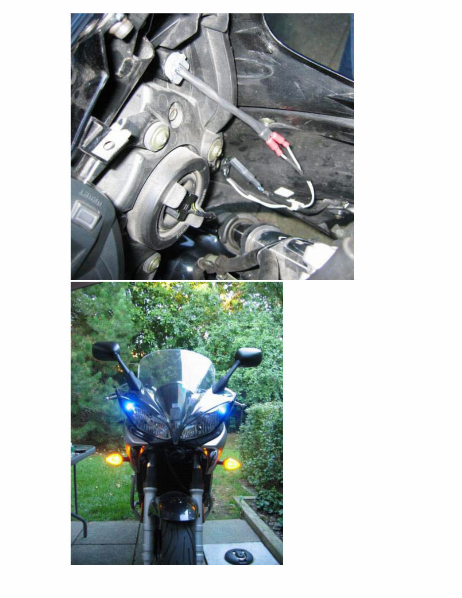
Step 6: Putting it all together.
This is definitely the most fun part of the project. We know things work so it’s just a
matter of connecting everything.
• Push the bulb sockets into the holes you’ve created in the headlight assembly.
• Replace the headlight assembly and upper fairing back onto the bike.
• Connect your new pod lights to your new wiring.
• Connect your turn signals.
• Test again just to make sure everything is working properly. Don’t forget to
make sure your turn signals are working properly still!
• Replace the inner panels and windscreen.
• Take pictures and post them on the FZ6 forums!
Image 9 (mod_pod_9.jpg): Everything is now wired up, and we're ready to replace
all the fairing bits.
Image 10 (mod_pod_10.jpg): We're done!
Special thanks to:
• The FZ6 forum community at SBN (sportbikes.net).
• greatzippy from the FZ6 forums on SBN. My mod was largely based on his
suggestion of R1 bulb sockets, 194 LEDs, and a number of tips regarding the
wiring.
• My Dad; I only hope I could one day have half the experience he's got doing
all this. Thanks for the help Pop!
Attached Thumbnails
You're Reading a Preview
What's Included?
Fast Download Speeds
Offline Viewing
Access Contents & Bookmarks
Full Search Facility
Print one or all pages of your manual
$39.99
Viewed 13 Times Today


Secure transaction
What's Included?
Fast Download Speeds
Offline Viewing
Access Contents & Bookmarks
Full Search Facility
Print one or all pages of your manual
$39.99
This workshop service repair manual is for the YAMAHA FZ6S FZ6N bike, including a parts catalogue and owner's manual. The manual covers a 600 cc 4-cylinder 4-stroke liquid-cooled DOHC engine and includes the following contents:
- General information
- Specifications
- Periodic checks
- Adjustments
- Engine system
- Camshaft
- Cylinder head
- Valve & valve spring
- Clutch & shift shaft
- Anti-lock brake system
- Immobilizer system
- Crankcase & crankshaft
- Connecting rods & pistons
- Transmission & balancers
- Cooling systems
- Fuel injection system
- Air induction system
- Electrical component
- Ignition system
- Starting system
- Charging system
- Lighting system
- Signaling system
- Wheel and brakes
- Hydraulic clutch
- Steering head/handlebars
- Swingarm/shaft drive
- Shock absorber
- Troubleshooting
- Wiring diagram
This comprehensive manual features detailed exploded views and step-by-step written procedures with pictures and diagrams. It is the same manual that technicians use for vehicle repairs and is suitable for both professional mechanics and DIY enthusiasts. The manual is fully printable, allowing for the selection of specific pages or the entire manual.


