EAS00002 NOTICE This manual was produced by the Yamaha Motor Company, Ltd. primarily for use by Yamaha deal- ers and their qualified mechanics. It is not possible to include all the knowledge of a mechanic in one manual. Therefore, anyone who uses this book to perform maintenance and repairs on Yamaha vehicles should have a basic understanding of mechanics and the techniques to repair these types of vehicles. Repair and maintenance work attempted by anyone without this knowledge is likely to render the vehicle unsafe and unfit for use. Yamaha Motor Company, Ltd. is continually striving to improve all of its models. Modifications and significant changes in specifications or procedures will be forwarded to all authorized Yamaha deal- ers and will appear in future editions of this manual where applicable. NOTE: @ Designs and specifications are subject to change without notice. EAS00004 IMPORTANT MANUAL INFORMATION Particularly important information is distinguished in this manual by the following. The Safety Alert Symbol means ATTENTION! BECOME ALERT! YOUR SAFETY IS INVOLVED! Failure to follow WARNING instructions could result in severe injury or death to the motorcycle operator, a bystander or a person checking or repairing the motorcycle. A CAUTION indicates special precautions that must be taken to avoid damage to the motorcycle. A NOTE provides key information to make procedures easier or clearer. WARNING CAUTION: NOTE:
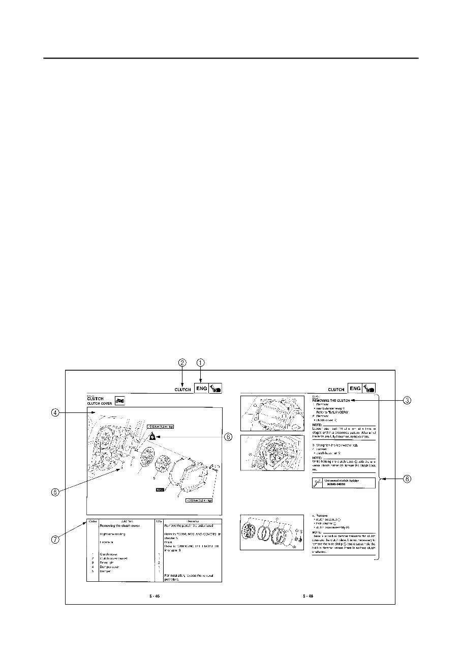
EAS00007 HOW TO USE THIS MANUAL This manual is intended as a handy, easy-to-read reference book for the mechanic. Comprehensive explanations of all installation, removal, disassembly, assembly, repair and check procedures are laid out with the individual steps in sequential order. 1 The manual is divided into chapters. An abbreviation and symbol in the upper right corner of each page indicate the current chapter. Refer to “SYMBOLS”. 2 Each chapter is divided into sections. The current section title is shown at the top of each page, except in chapter 3 (“PERIODIC CHECKS AND ADJUSTMENTS”), where the sub-section title(s) appears. 3 Sub-section titles appear in smaller print than the section title. 4 To help identify parts and clarify procedure steps, there are exploded diagrams at the start of each removal and disassembly section. 5 Numbers are given in the order of the jobs in the exploded diagram. A circled number indicates a disassembly step. 6 Symbols indicate parts to be lubricated or replaced. Refer to “SYMBOLS”. 7 A job instruction chart accompanies the exploded diagram, providing the order of jobs, names of parts, notes in jobs, etc. 8 Jobs requiring more information (such as special tools and technical data) are described sequen- tially.
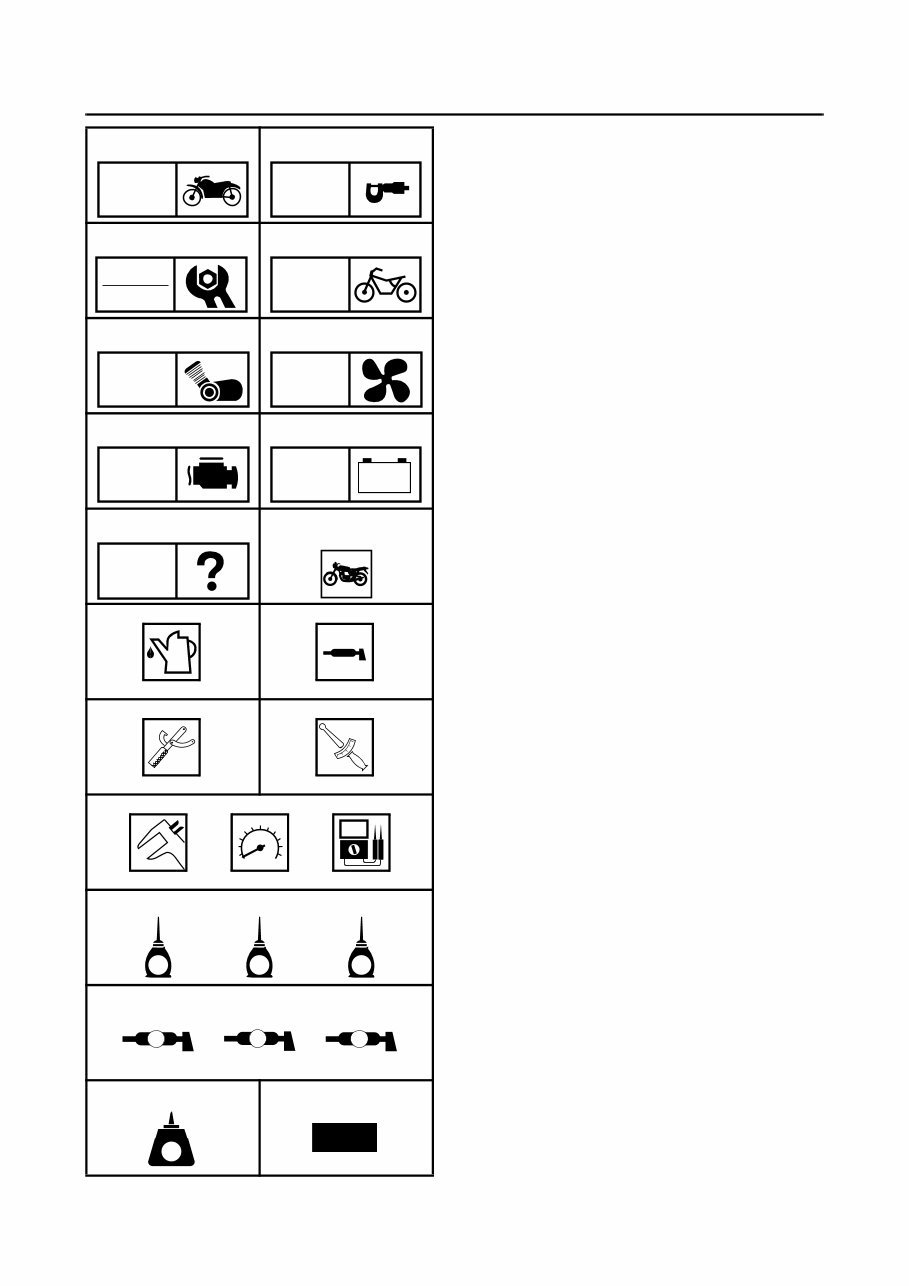
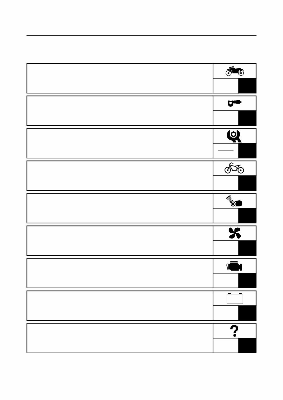
EAS00008 SYMBOLS The following symbols are not relevant to every vehicle. Symbols 1 to 9 indicate the subject of each chapter. 1 General information 2 Specifications 3 Periodic checks and adjustments 4 Chassis 5 Engine 6 Cooling system 7 Fuel injection system 8 Electrical system 9 Troubleshooting Symbols 0 to G indicate the following. 0 Serviceable with engine mounted A Filling fluid B Lubricant C Special tool D Tightening torque E Wear limit, clearance F Engine speed G Electrical data Symbols H to M in the exploded diagrams indicate the types of lubricants and lubrication points. H Engine oil I Gear oil J Molybdenum disulfide oil K Wheel bearing grease L Lithium soap base grease M Molybdenum disulfide grease Symbols N to O in the exploded diagrams indicate the following. N Apply locking agent (LOCTITE ® ) O Replace the part 1 2 3 4 5 6 7 8 9 0 A B C D E F G H I J K L M N O GEN INFO SPEC CHK ADJ CHAS ENG COOL FI – + ELEC TRBL SHTG T R . . E G M B LS M LT New
EAS00012 TABLE OF CONTENTS GENERAL INFORMATION GEN INFO 1 SPECIFICATIONS SPEC 2 PERIODIC CHECKS AND ADJUSTMENTS CHK ADJ 3 CHASSIS CHAS 4 ENGINE ENG 5 COOLING SYSTEM COOL 6 FUEL INJECTION SYSTEM FI 7 ELECTRICAL SYSTEM ELEC 8 TROUBLESHOOTING TRBL SHTG 9 – +
GEN INFO 1
GEN INFO CHAPTER 1 GENERAL INFORMATION MOTORCYCLE IDENTIFICATION .................................................................. 1-1 VEHICLE IDENTIFICATION NUMBER ..................................................... 1-1 MODEL CODE .......................................................................................... 1-1 FEATURES ...................................................................................................... 1-2 OUTLINE ................................................................................................... 1-2 FI SYSTEM................................................................................................ 1-3 COMPONENTS ......................................................................................... 1-5 FUEL INJECTION SYSTEM.................................................................... 1-17 THREE-WAY CATALYTIC CONVERTER SYSTEM ............................... 1-26 AIR INDUCTION SYSTEM ...................................................................... 1-30 COMPONENTS ....................................................................................... 1-31 IMPORTANT INFORMATION ....................................................................... 1-35 PREPARATION FOR REMOVAL AND DISASSEMBLY......................... 1-35 REPLACEMENT PARTS......................................................................... 1-35 GASKETS, OIL SEALS AND O-RINGS .................................................. 1-35 LOCK WASHERS/PLATES AND COTTER PINS ................................... 1-36 BEARINGS AND OIL SEALS .................................................................. 1-36 CIRCLIPS ................................................................................................ 1-36 CHECKING THE CONNECTIONS .......................................................... 1-37 SPECIAL TOOLS .......................................................................................... 1-38
You're Reading a Preview
What's Included?
Lifetime Access
Fast Download Speeds
Online & Offline Access
Access PDF Contents & Bookmarks
Full Search Facility
Print one or all pages of your manual
$24.99
Yamaha FJR1300(N,R) FJR 1300 N R COMPLETE OFFICIAL FACTORY Service / Repair / Workshop Manual
Get your hands on the complete official factory service, repair, and workshop manual for the Yamaha FJR1300(N,R) FJR 1300 N R. This manual is an invaluable resource for both professional mechanics and DIY enthusiasts, providing comprehensive information for the treatment and repair of the vehicle.
The manual covers the model codes 5JW1 (for Europe), 5JW2 (for F), and 5JW3 (for Oceania) for the 2001 model year, comprising a total of 617 pages. It is available in a printable .PDF format and is delivered instantly without any shipping costs or the need to wait for a CD-ROM.
For those looking to zoom in or out for detailed views, this manual supports the feature. The quality of the manual is factory standard, ensuring reliable and accurate information for all repair and service needs.
Whether you are in need of information related to carburetors, intake systems, camshafts, valve trains, ignition, fasteners, gaskets, bearings, or any other parts, this manual has got you covered. From fluid changes to brake replacements, engine repairs to electrical wiring diagrams, this comprehensive manual is a must-have for anyone working on the Yamaha FJR1300(N,R) FJR 1300 N R.
Reviews
Q&A
Recently Viewed
5,521,897Happy Clients
2,594,462eManuals
1,120,453Trusted Sellers
15Years in Business
Price:
Actual Price:
Yamaha FJR1300(N,R) FJR 1300 N R COMPLETE OFFICIAL FACTORY Service / Repair / Workshop Manual







 Lifetime Access




