
 Service Repair Maintenance Manual")
1988 Yamaha BIG Wheel (80cc) Service Repair Maintenance Manual
What's Included?
Fast Download Speeds
Online & Offline Access
Access PDF Contents & Bookmarks
Full Search Facility
Print one or all pages of your manual
OYAMAHA
LIT-11616-05-23 1 RV-28197-10
BW80S
SERVICE MANUAL
© 1985 by Yamaha Motor Corporation, U.S.A.
1st Edition, August 1985
All rights reserved. Any reprinting or
unauthorized use without the written
permission of Yamaha Motor Corporation,
U.S.A. is expressly prohibited.
Printed in U.S.A.
LIT-11616-05-23
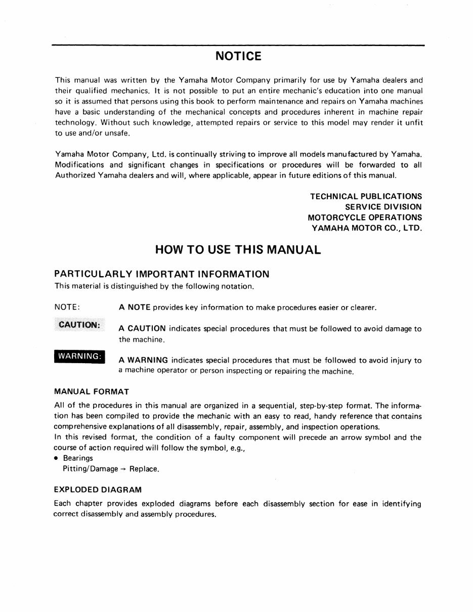
NOTICE
This manual was written by the Yamaha Motor Company primarily for use by Yamaha dealers and
their qualified mechanics. It is not possible to put an entire mechanic's education into one manual
so it is assumed that persons using this book to perform maintenance and repairs on Yamaha machines
have a basic understanding of the mechanical concepts and procedures inherent in machine repair
technology. Without such knowledge, attempted repairs or service to this model may render it unfit
to use and/or unsafe.
Yamaha Motor Company, ltd. is continually striving to improve all models manufactured by Yamaha.
Modifications and significant changes in specifications or procedures will be forwarded to all
Authorized Yamaha dealers and will, where applicable, appear in future editions of this manual.
TECHNICAL PUBL !CATIONS
SERVICE DIVISION
MOTORCYCLE OPERATIONS
YAMAHA MOTOR CO., LTO.
HOW TO USE THIS MANUAL
PARTICULARLY IMPORTANT INFORMATION
This material is distinguished by the following notation.
NOTE:
~;%11t.fiti~~i)·
WARNING:
A NOTE provides key information to make procedures easier or clearer.
A CAUTION indicates special procedures that must be followed to avoid damage to
the machine.
A WARNING indicates special procedures that must be followed to avoid injury to
a machine operator or person inspecting or repairing the machine.
MANUAL FORMAT
All of the procedures in this manual are organized in a sequential, step-by-step format. The informa-
tion has been compiled to provide the mechanic with an easy to read, handy reference that contains
comprehensive explanations of all disassembly, repair, assembly, and inspection operations.
In this revised format, the condition of a faulty component will precede an arrow symbol and the
course of action required will follow the symbol, e.g.,
• Bearings
Pitting/Damage --+ Replace.
EXPLODED DIAGRAM
Each chapter provides exploded diagrams before each disassembly section for ease in identifying
correct disassembly and assembly procedures.
CD 0
l~%l.~eal
l~&.fl§ll
0 0
I ENG l'-1
~KI
® ®
PRBifl
jcHASI cfJol
0 ®
jELECI iii I
IAPPxl~ 'I
®
~
@)
~
@
~
@
~
@
[0]
@
[mJ
@
1
@
1
@
1
-
a
-
m B
@) @)
@
~ ~ ~
@
A
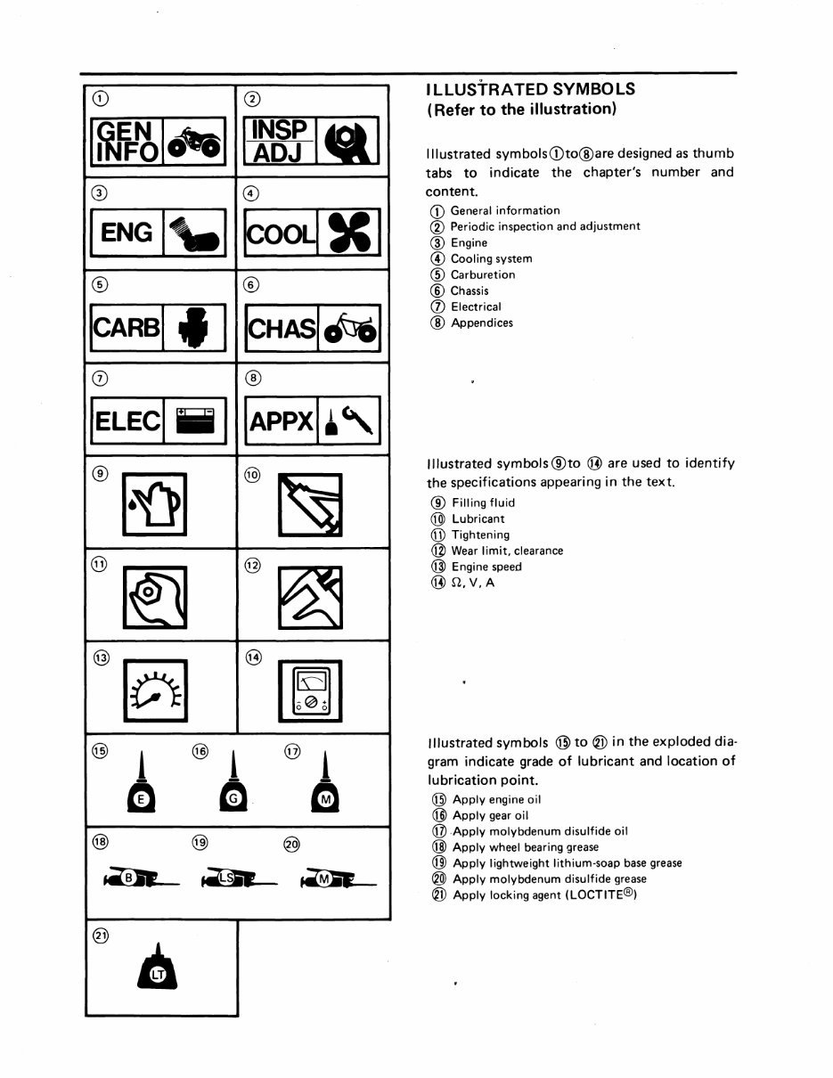
ILLUSTRATED SYMBOLS
(Refer to the illustration)
Illustrated symbolsCDto@are designed as thumb
tabs to indicate the chapter's number and
content.
CD General information
® Periodic inspection and adjustment
@Engine
@ Cooling system
@ Carburetion
®Chassis
(J) Electrical
® Appendices
Illustrated symbols ®to ® are used to identify
the specifications appearing in the text.
® Filling fluid
(j]) Lubricant
@ Tightening
@ Wear limit, clearance
@ Engine speed
@rl.,V,A
Illustrated symbols @to® in the exploded dia-
gram indicate grade of lubricant and location of
lubrication point.
@ Apply engine oil
@ Apply gear oil
@.Apply molybdenum disulfide oil
@) Apply wheel bearing grease
(j]) Apply lightweight lithium-soap base grease
® Apply molybdenum disulfide grease
@ Apply locking agent (LOCTITE®)
INDEX
GENERAL INFORMATION
PERIODIC INSPECTIONS
AND ADJUSTMENTS
ENGINE
CARBURETION
CHASSIS
ELECTRICAL
APPENDICES .
'-
ENG
Iii
ELEC
~'
APPX
CHAPTER 1.
GENERAL INFORMATION
MACHINE IDENTIFICATION .................................... 1-1
VEHICLE IDENTIFICATION NUMBER ......................... 1-1
ENGINE SERIAL NUMBER .................................. 1-1
IMPORTANT INFORMATION .................................... 1-2
ALL REPLACEMENT PARTS ................................. 1-2
GASKETS, OIL SEALS, AND 0-RINGS ........................ 1-2
LOCK WASHERS/PLATES AND COTTER PINS .................. 1-2
BEARINGS AND OIL SEALS ................................ 1-2
Cl RCLIPS ................................................. 1-3
SPECIAL TOOLS .............................................. 1-3
FOR TUNE-UP ............................................. 1-3
FOR ENGINE SERVICE ..................................... 1-4
FOR CHASSIS SERVICE ...................................... 1-4
FOR ELECTRICAL COMPONENTS ............................. 1-5
1-1
GENERAL
INFORMATION
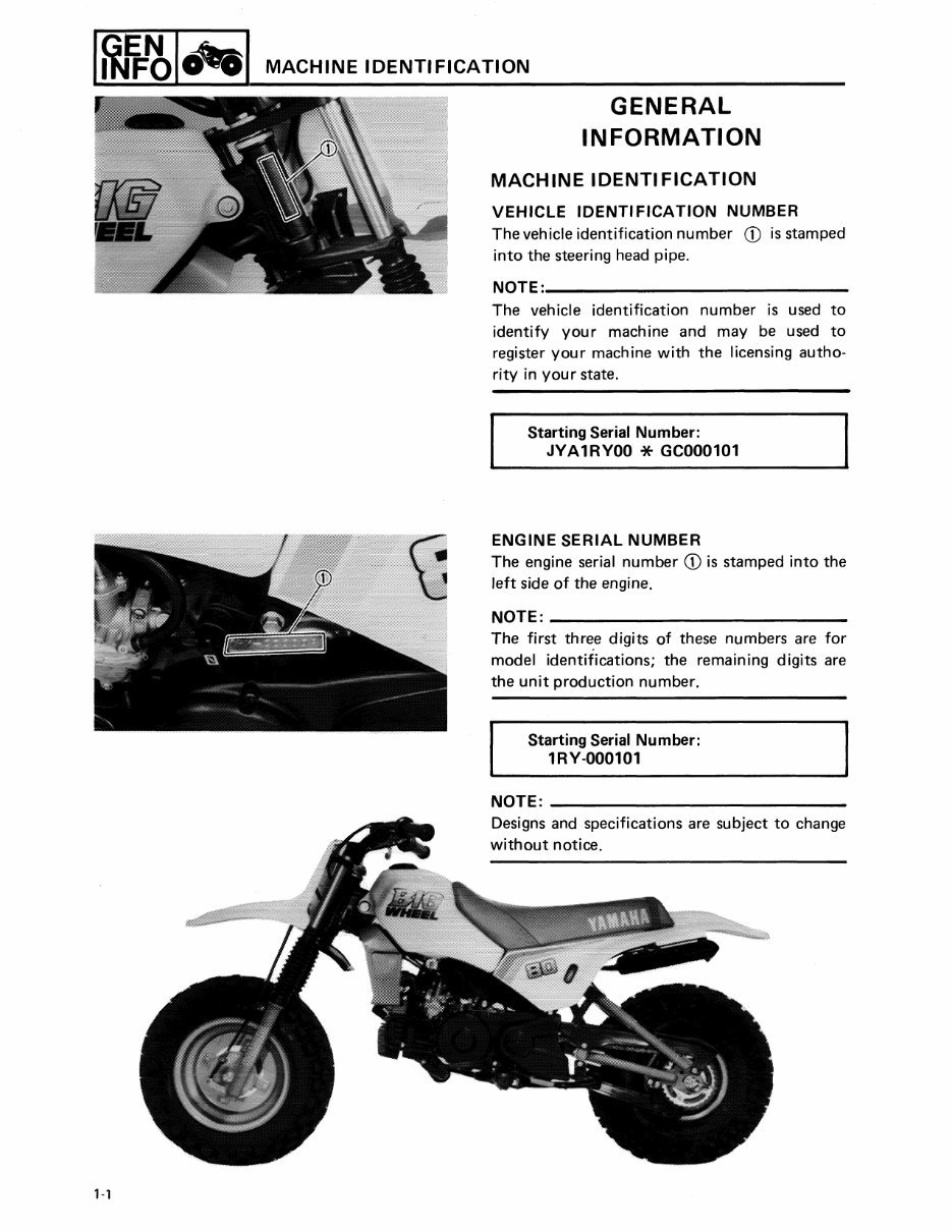
MACHINE IDENTIFICATION
VEHICLE IDENTIFICATION NUMBER
The vehicle identification number CD is stamped
into the steering head pipe.
NOTE:-------------
The vehicle identification number is used to
identify your machine and may be used to
register your machine with the licensing autho-
rity in your state.
Starting Serial Number:
JYA1RYOO * GC000101
ENGINE SERIAL NUMBER
The engine serial number CD is stamped into the
left side of the engine.
NOTE:-------------------------
The first three digits of these numbers are for
model identifications; the remaining digits are
the unit production number.
Starting Serial Number:
1RY-000101
NOTE:------------------
Designs and specifications are subject to change
without notice.
IMPORTANT INFORMATION ~~lj:.~~~~
IMPORTANT INFORMATION
All REPLACEMENT PARTS
1. We recommend to use Yamaha genuine parts
for all replacements. Use oil and/or grease
recommended by Yamaha for assembly and
adjustment.
GASKETS, OIL SEALS, AND 0-RINGS
1. All gaskets, seals, and 0-rings should be
replaced when an engine is overhauled. All
gasket surfaces, oil seal lips, and 0-rings
must be cleaned.
2. Properly oil all mating parts and bearings
during reassembly. Apply grease to the oil
seal lips.
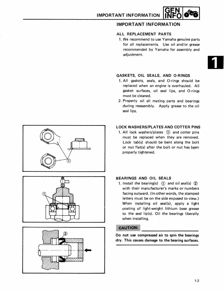
LOCK WASHERS/PLATES AND COTTER PINS
1. All lock washers/plates CD and cotter pins
must be replaced when they are removed.
Lock tab(s) should be bent along the bolt
or nut flat(s) after the bolt or nut has b{!en
properly tightened.
BEARINGS AND OIL SEALS
1. Install the bearing(s) CD and oil seal (s) ®
with their manufacturer's marks or numbers
facing outward. (In other words, the stamped
letters must be on the side exposed to view.)
When installing oil seal(s), apply a light
coating of light-weight lithium base grease
to the seal lip(s). Oil the bearings liberally
when installing.
Do not use compressed air to spin the bearings
dry. This causes damage to the bearing surfaces.
1-2
n
SPECIAL TOOLS
1-3
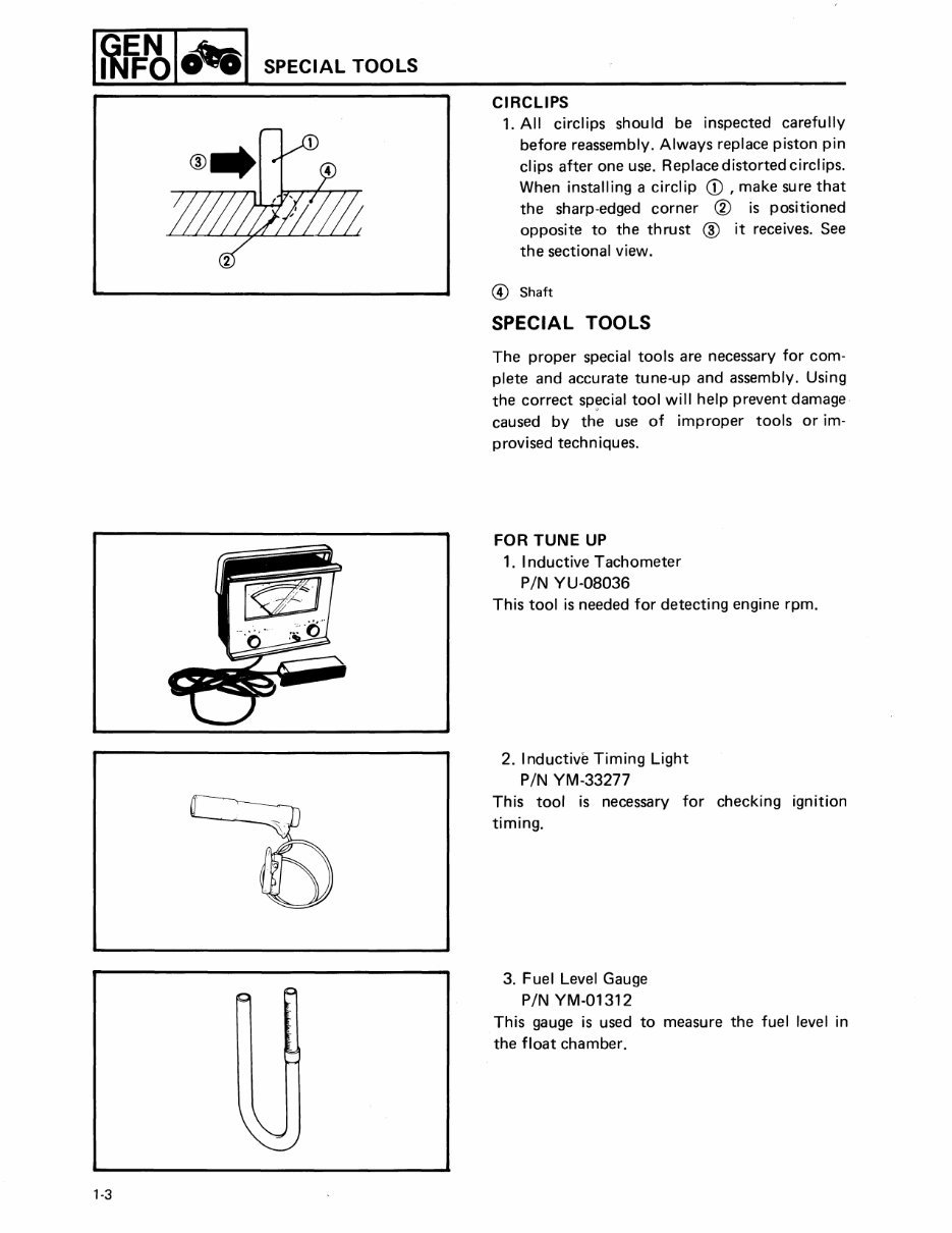
CIRCLIPS
1. All circlips should be inspected carefully
before reassembly_ Always replace piston pin
clips after one use. Replace distorted circlips.
When installing a circlip CD , make sure that
the sharp-edged corner ® is positioned
opposite to the thrust ® it receives. See
the sectional view.
@ Shaft
SPECIAL TOOLS
The proper special tools are necessary for com-
plete and accurate tune-up and assembly. Using
the correct sp~cial tool will help prevent damage
caused by the use of improper tools or im-
provised techniques.
FOR TUNE UP
1. Inductive Tachometer
P/N YU-08036
This tool is needed for detecting engine rpm.
2. Inductive Timing Light
P/N YM-33277
This tool is necessary for checking ignition
timing.
3. Fuel Level Gauge
P/N YM-01312
This gauge is used to measure the fuel level in
the float chamber.
SPECIAL TOOLS
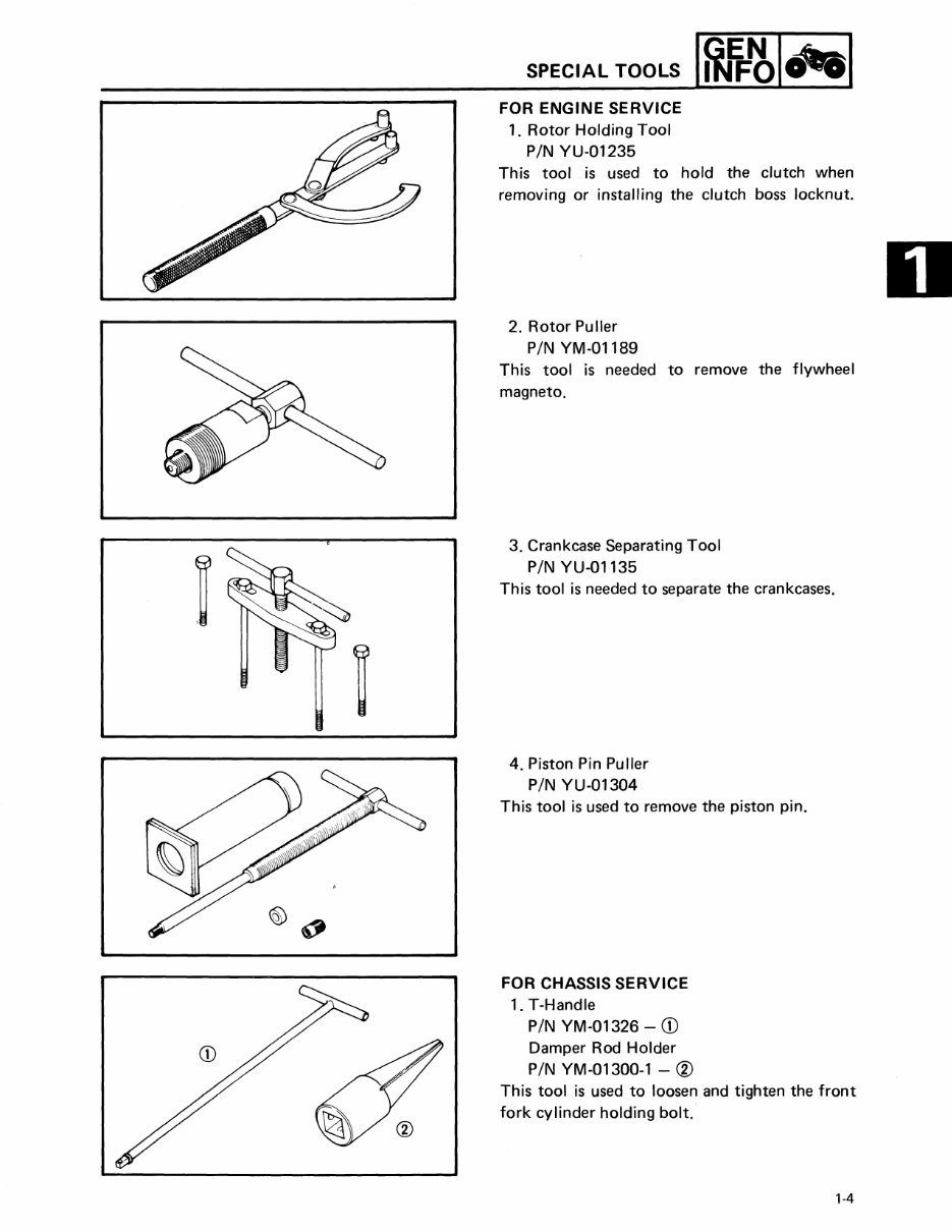
FOR ENGINE SERVICE
1. Rotor Holding Tool
P/N YU-01235
This tool is used to hold the clutch when
removing or installing the clutch boss locknut.
2. Rotor Puller
P/N YM-01189
This tool is needed to remove the flywheel
magneto.
3. Crankcase Separating Tool
P/N YU-01135
This tool is needed to separate the crankcases.
4. Piston Pin Puller
P/N YU-01304
This tool is used to remove the piston pin.
FOR CHASSIS SERVICE
1. T-Handle
P/N YM-01326- CD
Damper Rod Holder
P/N YM-01300-1- ®
This tool is used to loosen and tighten the front
fork cylinder holding bolt.
1-4
You're Reading a Preview
What's Included?
Fast Download Speeds
Online & Offline Access
Access PDF Contents & Bookmarks
Full Search Facility
Print one or all pages of your manual
$35.99
Viewed 13 Times Today


Secure transaction
What's Included?
Fast Download Speeds
Online & Offline Access
Access PDF Contents & Bookmarks
Full Search Facility
Print one or all pages of your manual
$35.99
This manual covers the 1988 Yamaha BIG WHEEL (80cc) Motorcycle Service Manual. It provides step-by-step procedures for disassembly, repair, assembly, and inspection operations. Each chapter includes exploded diagrams before the disassembly section to facilitate correct procedures. The manual is fully bookmarked and searchable, offering comprehensive explanations for all aspects of the motorcycle. It is a high-quality manual created in the computer, not a cheap scan of a paper manual. This manual is useful for both professional mechanics and DIY enthusiasts.


