


SERVICE
MANUAL
YQ50
CAUTION:
WARNING
NOTICE
This manual was written by the MBK INDUSTRIE primarily for use by YAMAHA and MBK dealers
and their qualified mechanics. It is not possible to put an entire mechanic’s education into one manual,
so it is assumed that persons using this book to perform maintenance and repairs on YAMAHA and
MBK scooters have a basic understanding of the mechanical concepts and procedures inherent in
scooter repair technology. Without such knowledge, attempted repairs or service to this model may
render it unfit to use and/or unsafe.
MBK INDUSTRIE is continually striving to improve all models manufactured. Modifications and
significant changes in specifications or procedures will be forwarded to all Authorized YAMAHA and
MBK dealers and will, where applicable, appear in future editions of this manual.
DOCUMENTATION TECHNIQUE
MBK INDUSTRIE
PARTICULARY IMPORTANT INFORMATION
This material is distinguished by the following notation :
The safety Alert Symbol means ATTENTION! BECOME ALERT! YOUR
SAFETY IS INVOLVED!
Failure to follow WARNING instructions could result in severe injury or
death to the scooter operator, a bystander, or a person inspecting or
repairing the scooter.
A CAUTION indicates special precautions that must be taken to avoid
damage to the scooter.
A NOTE provides key information to make procedures easier or clearer. NOTE:
HOW TO USE THIS MANUAL
CONSTRUCTION OF THIS MANUAL
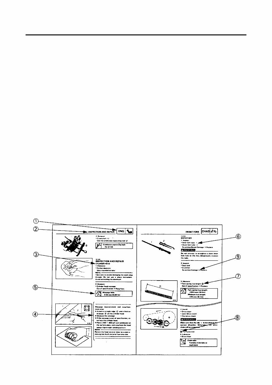
This manual consists of chapters for the main categories of subjects. (See «illustrated symbols).
1st title 1 This is a chapter with its symbol on the upper right of each page.
2nd title 2 This title appears on the upper of each page on the left of the chapter symbol. (For
the chapter «Periodic inspection and adjustment» the 3rd title appears.)
3rd title 3 This is a final title.
MANUAL FORMAT
All of the procedures in this manual are organized in a sequential, step-by-step format. The informa-
tion has been compiled to provide the mechanic with an easy to read, handy reference that contains
comprehensive explanations of all disassembly, repair, assembly, and inspections.
A set of particulary important procedure 4 is placed between a line of asterisks "
*
" with each step
preceded by "
•
".
IMPORTANT FEATURES
• Data and a special tools are framed in a box preceded by a relevant symbol 5.
• An encircled numeral 6 indicates a part name, and an encircled alphabetical letter data for an
alignement mark 7, the others being indicated by an alphabetical letter in a box 8.
• A condition of a faulty component will precede an arrow symbol and the course of action required
the symbol 9.
EXPLODED DIAGRAM
Each chapter provides exploded diagrams are before each disassembly section for ease in identifying
correct disassembly and assembly procedures.
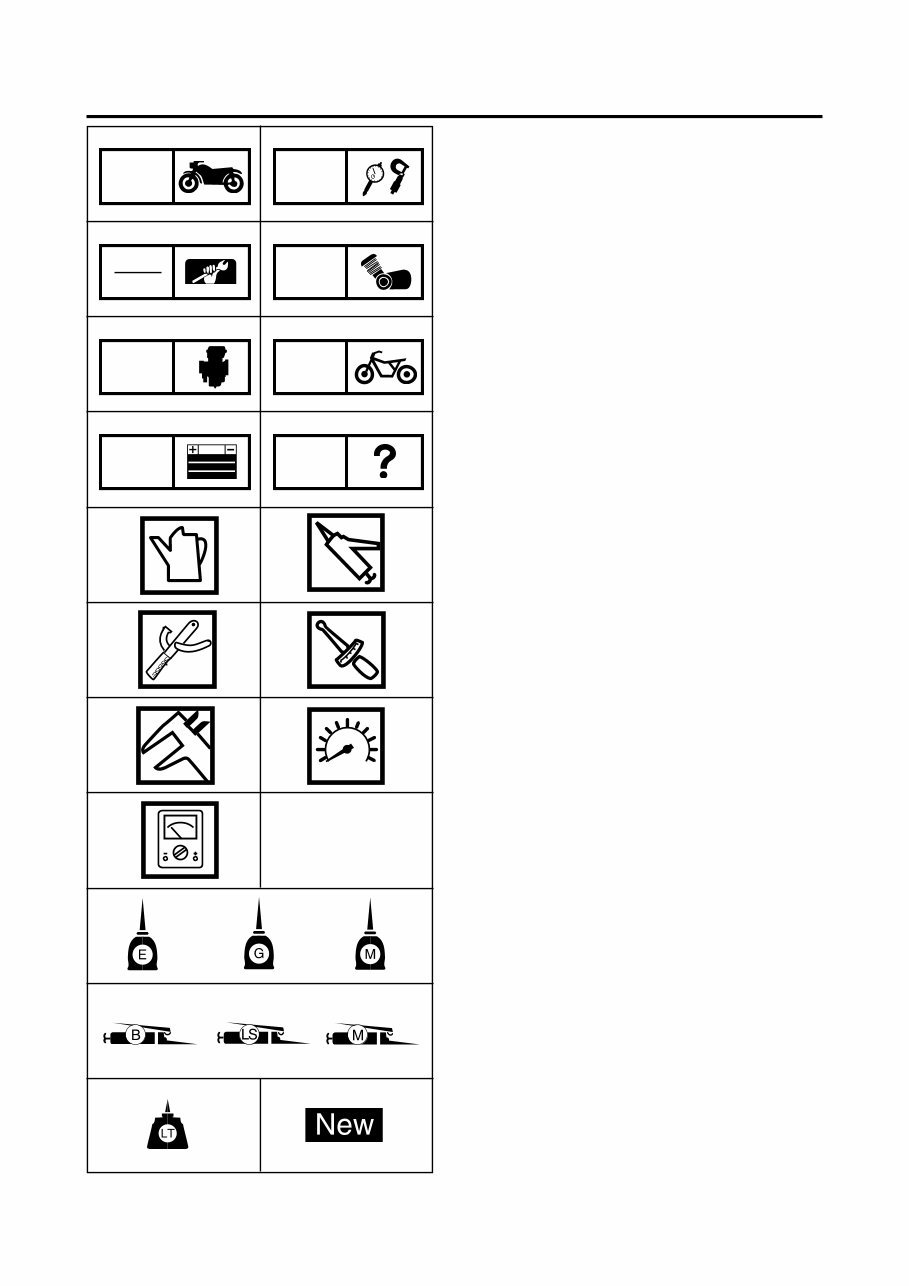
ILLUSTRATED SYMBOLS
(REFER TO THE ILLUSTRATION)
Illustrated symbols Q to W are designed as
thumb tabs to indicate the chapter’s number and
content.
Q General information
W Specifications
E Periodic inspection and adjustment
R Engine
T Carburetion
Y Chassis
U Electrical
I Troubleshooting
Illustrated symbols O to e are used to identify
the specifications appearing in the text.
O Filling fluid
P Lubricant
{ Special tool
} Tightening
q Wear limit, clearance
w Engine speed
e Ω, V, A
Illustrated symbols r to [ in the exploded
diagram indicate grade of lubricant and location
of lubrication point.
r Apply engine oil
t Apply gear oil
y Apply molybdenum disulfide oil
u Apply wheel bearing grease
i Apply lightweight lithium-soap base
grease
o Apply molybdenum disulfide grease
p Apply locking agent (THREADLOCK ®)
[ Use new one
INSP
ADJ
TRBL
SHTG
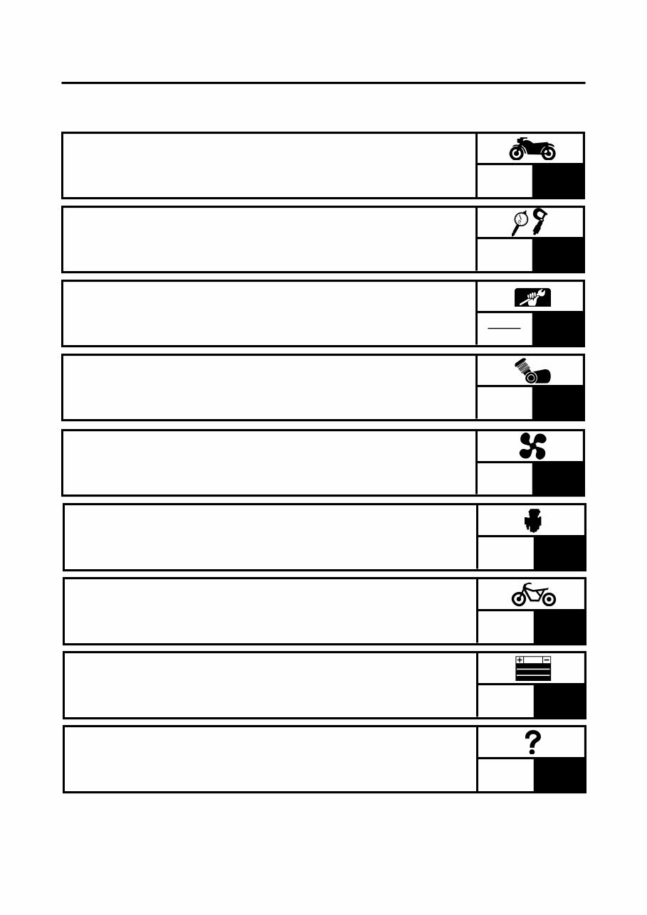
GEN
INFO
ENG
CHAS CARB
ELEC
SPEC
T.R
Q W
R E
T Y
U I
O P
{ }
q w
e
r
u
p [
t y
i o
1
2
3
4
6
7
8
9
INDEX
SPECIFICATIONS
ENGINE OVERHAUL
CARBURETION
CHASSIS
ELECTRICAL
TROUBLESHOOTING
GENERAL INFORMATION
PERIODIC INSPECTION
AND ADJUSTMENT
SPEC
ENG
CARB
CHAS
ELEC
TRBL
SHTG
GEN
INFO
INSP
ADJ
5
COOLING SYSTEM
ENG
1
GEN
INFO
GEN
INFO
CHAPTER 1.
GENERAL INFORMATION
SCOOTER IDENTIFICATION ........................................................................ 1-1
VEHICLE IDENTIFICATION NUMBER .................................................... 1-1
ENGINE SERIAL NUMBER ..................................................................... 1-1
IMPORTANT INFORMATION ....................................................................... 1-2
ALL REPLACEMENT PARTS ................................................................. 1-2
GASKETS, OIL SEALS, AND O-RINGS .................................................. 1-2
LOCK WASHERS/PLATES AND COTTER PINS .................................... 1-2
BEARINGS AND OIL SEALS ................................................................... 1-2
CIRCLIPS ................................................................................................. 1-3
SPECIAL TOOLS ........................................................................................... 1-4
GEN
INFO
1-1
GENERAL INFORMATION
SCOOTER IDENTIFICATION
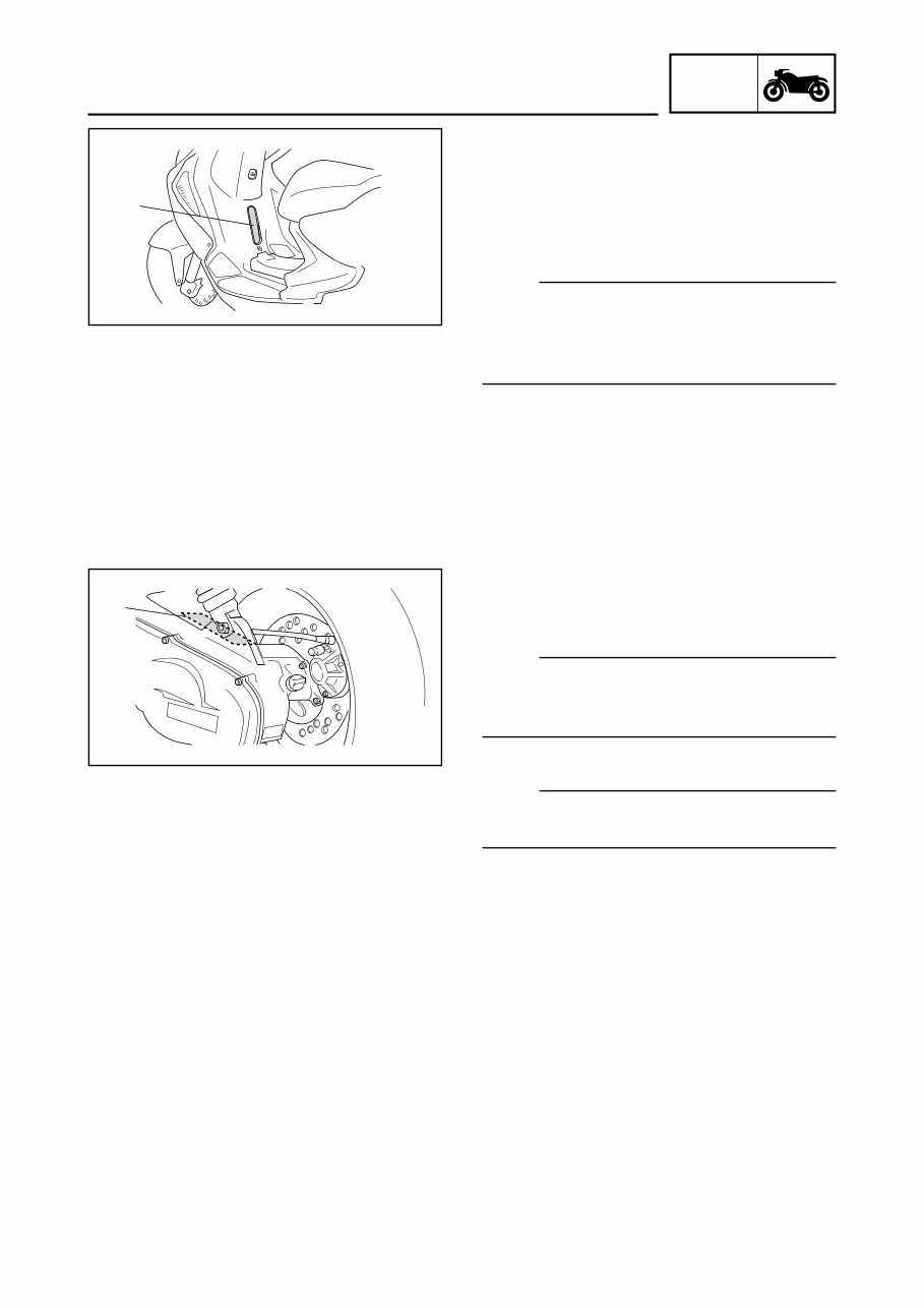
VEHICLE IDENTIFICATION NUMBER
The vehicle identification number Q is stamped
into the frame.
NOTE:
The vehicle identification number is used to
identify your scooter and may be used to register
your scooter with the licensing authority in your
state.
ENGINE SERIAL NUMBER
The engine serial number Q is stamped into the
crankcase.
NOTE:
The first three digits of these numbers are for
model identifications; the remaining digits are
the unit production number.
NOTE:
Designs and specifications are subject to change
without notice.
SCOOTER IDENTIFICATION
GEN
INFO
1-2
IMPORTANT INFORMATION
IMPORTANT INFORMATION
ALL REPLACEMENT PARTS
1.Use only genuine parts for all replacements.
Use oil and/or grease recommended by MBK/
YAMAHA for assembly and adjustment. Other
brands may be similar in function and
appearance, but inferior in quality.
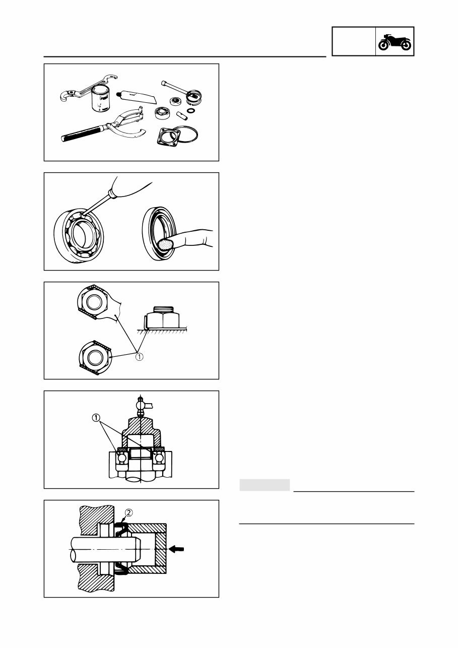
GASKETS, OIL SEALS, AND O-RINGS
1.All gaskets, seals and O-rings should be
replaced when an engine is overhauled. All
gaskets surfaces, oil seal lips and O-rings
must be cleaned.
2.Properly oil all mating parts and bearing during
reassembly. Apply grease to the oil seal lips.
LOCK WASHERS/PLATES AND COTTER
PINS
1.All lock washers/plates Q and cotter pins
must be replaced when they are removed.
Lock tab(s) should be bent along the bolt or nut
flat(s) after the bolt or nut has been properly
tightened.
BEARINGS AND OIL SEALS
1.Install the bearing(s) Q and oil seal(s) W with
their manufacturer’s marks or numbers facing
outward. (In other words, the stamped letters
must be on the side exposed to view.) When
installing oil seal(s), apply a light coating of
lightweight lithium base grease to the seal
lip(s). Oil the bearings liberally when installing.
Do not use compressed air to spin the
bearings dry. This causes damage to the
bearing surfaces.
CAUTION :
GEN
INFO
1-3
IMPORTANT INFORMATION
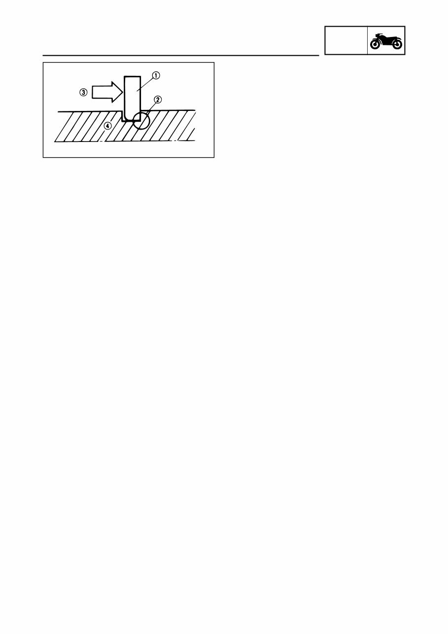
CIRCLIPS
1.All circlips should be inspected carefully before
reassembly. Always replace piston pin clips
once they have been removed. Replace bent
circlips. When installing a circlip Q make sure
that the sharp edge W is positioned opposite
to the thrust E it receives. See the sectional
view.
R Shaft
You're Reading a Preview
What's Included?
Fast Download Speeds
Online & Offline Access
Access PDF Contents & Bookmarks
Full Search Facility
Print one or all pages of your manual
$28.99
1997 Yamaha Aerox YQ50 Service Repair Manual
Viewed 52 Times Today

What's Included?
Fast Download Speeds
Online & Offline Access
Access PDF Contents & Bookmarks
Full Search Facility
Print one or all pages of your manual
$28.99

Secure transaction
What's Included?
Fast Download Speeds
Online & Offline Access
Access PDF Contents & Bookmarks
Full Search Facility
Print one or all pages of your manual
Description
A 1997 Yamaha Aerox YQ50 Service Repair Manual is available for those interested in DIY car repair. This comprehensive manual includes detailed instructions and step-by-step diagrams for all workshop procedures, making it useful for both professional mechanics and DIY enthusiasts.
Benefits of servicing and repairing your car yourself include having an excuse to avoid other household chores, the opportunity to acquire new tools, and the potential to save money. It covers the 1997 Yamaha Aerox YQ50 model and includes the following:
- General Maintenance
- Troubleshooting
- Engine Service/Repair
- Transmission Service/Repair
- Brake System
- Electrical System
- Suspension
- Wiring Diagram
- Periodic Lubrication
- Steering
- Cooling System
- Fuel Injection/Fuel System
- Emission System
- Heater/Air Conditioning
- Engine Control System
- Chassis/Body
- Restraint System
- Interior
- Differential/Drive Axle
The manual is available in PDF format and is compatible with all versions of Windows and Mac. It is written in English and requires Adobe Reader for access.


