

Year 2000
Repair Manual

TABLE OF CONTENTS
Chapter 1: General Information
1.1 URAL Specifications . . . . . . . . . . . . . . . . . . . . . . . . . . . .. . . . . . . . . . . . . . . . . . . . .
.
1
1.2 Maintenance, Lubrication and Tune-up . . . . . . . . . . . . . . . . . . . . . . . . . . . . . . . . . . . 6
1.3 Normal Operation . . . . . . . . . . . . . . . . . . . . . . . . . . . . . . . . . . . . . . . . . . . . . . . . . . . . 10
1.4 Troubleshooting . . . . . . . . . . . . . . . . . . . . . . . . . . . . . . . . . . . . . . . . . . . . . . . . . . . . . 15
1.5 General Dismantling and Repair Techniques . . . . . . . . . . . . . . . . . . . . . . . . . . . . . . 30
Chapter 2: Chassis and Running Gear
2.1 Description and General Specifications . . . . . . . . . . . . . . . . . . . . . . . . . . . . . . . . . . 36
2.2 Operating Controls . . . . . . . . . . . . . . . . . . . . . . . . . . . . . . . . . . . . . . . . . . . . . . . . . . 38
2.3 Front Fork and Suspension . . . . . . . . . . . . . . . . . . . . . . . . . . . . . . . . . . . . . . . . . . . . 44
2.4 Rear Suspension . . . . . . . . . . . . . . . . . . . . . . . . . . . . . . . . . . . . . . . . . . . . . . . . . . . . 50
2.5 Brakes . . . . . . . . . . . . . . . . . . . . . . . . . . . . . . . . . . . . . . . . . . . . . . . . . . . . . . . . . . . . 51
2.6 Wheels, Tires, Shock Absorbers and Springs . . . . . . . . . . . . . . . . . . . . . . . . . . . . . 54
2.7 Fenders . . . . . . . . . . . . . . . . . . . . . . . . . . . . . . . . . . . . . . .. . . . . . . . . . . . . . . . . . . . . 62
2.8 Bench Seats . . . . . . . . . . . . . . . . . . . . . . . . . . . . . . . . . . . . . . . . . . . . . . . . . . . . . . . . 62
2.9 Windshield and Fairing . . . . . . . . . . . . . . . . . . . . . . . . . . . . . . . . . . . . . . . . . . . . . . . 62
Chapter 3: Sidecar
3.1 Description and General Specifications . . . . . . . . . . . . . . . . . . . . . . . . . . . . . . . . . . 65
3.2 Installation and Removal . . . . . . . . . . . . . . . . . . . . . . . . . . . . . . . . . . . . . . . . . . . . . . 66
3.3 Sidecar Alignment . . . . . . . . . . . . . . . . . . . . . . . . . . . . . . . . . . . . . . . . . . . . . . . . . . . 67
3.4 Frame/Attachment . . . . . . . . . . . . . . . . . . . . . . .. . .. . . . . . . . . . . . . . . . . . . . . . . . . . 69
3.5 Suspension . . . . . . . . . . . . . . . . . . . . . . . . . . . . . . . . . . . . . . . . . . . . . . . . . . . . . . . . . 70
3.6 Sidecar body . . . . . . . . . . . . . . . . . . . . . . . . . . . . . . . . . . . . . . . . . . . . . . . . . . . . . . . 71
3.7 Handling Differences Between Single & Dual Wheel Drive . . . . . . . . . . . . . . . . . . . 72
3.8 Driven Sidecar Wheel . . . . . . . . . . . . . . . . . . . . . . . . . . . . . . . . . . . . . . . . . . . . . . . . 73
3.9 Fender . . . . . . . . . . . . . . . . . . . . . . . . . . . . . . . . . . . . . . . . . . . . . . . . . . . . . . . . . . . . 77
3.10 Upholstery . . . . . . . . . . . . . . . . . . . . . . . . . . . . . . . . . . . . . . . . . . . . . . . . . . . . . . . . 77
Chapter 4: Engine
4.1 Description and General Specifications . . . . . . . . . . . . . . . . . . . . . . . . . . . . . . . . . . 78
4.2 Repair Information and Service Limits . . . . . . . . . . . . . . . . . . . . . . . . . . . . . . . . . . . 83
4.3 Cylinder Heads and Valves . . . . . . . . . . . . . . . . . . . . . . . . . . . . . . . . . . . . . . . . . . . . 84
4.4 Cylinders and Pistons . . . . . . . . . . . . . . . . . . . . . . . . . . . . . . . . . . . . . . . . . . . . . . . . 93
4.5 Camshaft, Timing Gears, Tappets . . . . . . . . . . . . . . . . . . . . . . . . . . . . . . . . . . . . . . . 99
4.6 Oil Pump and Delivery . . . . . . . . . . . . . . . . . . . . . . . . . . . . . . . . . . . . . . . . . . . . . . . . 102
4.7 Removing and Reinstalling the Flywheel . . . . . . . . . . . . . . . . . . . . . . . . . . . . . . . . . . 105
4.8 Crankshaft and Connecting Rods . . . . . . . . . . . . . . . . . . . . . . . . . . . . . . . . . . . . . . . 106
4.9 Crankcase and Covers . . . . . . . . . . . . . . . . . . . . . . . . . . . . . . . . . . . . . . . . . . . . . . . 112

Chapter 5: Gearbox
5.1 Description and Specifications . . . . . . . . . . . . . . . . . . . . . . . . . . . . . . . . . . . . . . . . . . 113
5.2 Gearbox (Solo Motorcycle) . . . . . . . . . . . . . . . . . . . . . . . . . . . . . . . . . . . . . . . . . . . . 118
5.3 Shift Mechanism Adjustment . . . . . . . . . . . . . . . . . . . . . . . . . . . . . . . . . . . . . . . . . . . 121
5.4 Gearbox Removal and Installation . . . . . . . . . . . . . . . . . . . . . . . . . . . . . . . . . . . . . . 123
5.5 Gearbox Disassembly and Reassembly . . . . . . . . . . . . . . . . . . . . . . . . . . . . . . . . . 124
5.6 Repairing the Gearbox Assembly Units and Parts . . . . . . . . . . . . . . . . . . . . . . . . . 127
Chapter 6: Clutch
6.1 Description and Specifications . . . . . . . . . . . . . . . . . . . . . . . . . . . . . . . . . . . . . . . . . 133
6.2 Clutch Adjustment . . . . . . . . . . . . . . . . . . . . . . . . . . . . . . . . . . . . . . . . . . . . . . . . . . . 134
6.3 Removing and Reinstalling the Clutch Release Mechanism . . . . . . . . . . . . . . . . . . 134
6.4 Clutch Repairs . . . . . . . . . . . . . . . . . . . . . . . . . . . . . . . . . .. . . . . . . . . . . . . . . . . . . . 135
6.5 Clutch Reassembly . . . . . . . . . . . . . . . . . . . . . . . . . . . . . . . . . . . . . . . . . . . . . . . . . . 136
Chapter 7: Driveshaft and Final Drive
7.1 Description and Specifications . . . . . . . . . . . . . . . . . . . . . . . . . . . . . . . . . . . . . . . . . . 137
7.2 Removal and Installation of Final Drive . . . . . . . . . . . . . . . . . . . . . . . . . . . . . . . . . . . 138
7.3 Removing and Reinstalling Propellor Shaft . . . . . . . . . . . . . . . . . . . . . . . . . . . . . . . . 138
7.4 Removing and Reinstalling the Rear Swing Arm . . . . . . . . . . . .. . . . . . . . . . . . . . . . 139
7.5 Driveshaft and Universal Joint Repair . . . . . . . . . . . . . . . . . . . . . . . . . . . . . . . . . . . . 139
7.6 Final Drive Disassembly . . . . . . . . . . . . . . . . . . . . . . . . . . . . . . . . . . . . . . . . . . . . . . 141
7.7 Repairing the Final Drive . . . . . . . . . . . . . . . . . . . . . . . . . . . . . . . . . . . . . . . . . . . . . . 143
7.8 Final Drive with Driven Sidecar Wheel (Sportsman) . . . . . .. . . . . . . . . . . . . . . . . . . 145
Chapter 8: Electrical
8.1 Description and Specifications . . . . . . . . . . . . . . . . . . . . . . . . . . . . . . . . . . . . . . . . . . 147
8.2 Maintenance and Troubleshooting . . . . . . . . . . . . . . . . . . . . . . . . . . . . . . . . . . . . . . 147
8.3 Battery . . . . . . . . . . . . . . . . . . . . . . . . . . . . . . . . . . . . . . . . . . . . . . . . . . . . . . . . . . . . 149
8.4 Alternator . . . . . . . . . . . . . . . . . . . . . . . . . . . . . . . . . . . . . . . . . . . . . . . . . . . . . . . . . . 153
8.5 Ignition . . . . . . . . . . . . . . . . . . . . . . . . . . . . . . . . . . . . . . . . . . . . . . . . . . . . . . . . . . . . 155
8.6 Lights . . . . . . . . . . . . . . . . . . . . . . . . . . . . . . . . . . . . . . . . . . . . . . . . . . . . . . . . . . . . . 158
8.7 Horn . . . . . . . . . . . . . . . . . . . . . . . . . . . . . . . . . . . . . . . . . . . . . . . . . . . . . . . . . . . . . . 159
8.8 Turn Signals . . . . . . . . . . . . . . . . . . . . . . . . . . . . . . . . . . . . . . . . . . . . . . . . . . . . . . . . 159
8.9 Wiring, Switches, Fuses, Connectors . . . . . . . . . . . . . . . . . . . . . . . . . . . . . . . . . . . . 160
Chapter 9: Fuel, Carburetion, Air Intake, Exhaust
9.1 Description and Specifications . . . . . . . . . . . . . . . . . . . . . . . . . . . . . . . . . . . . . . . . . . 161
9.2 Fuel Tank, Fuel Valve . . . . . . . . . . . . . . . . . . . . . . . . . . . . . . . . . . . . . . . . . . . . . . . . 161
9.3 Carburetors . . . . . . . . . . . . . . . . . . . . . . . . . . . . . . . . . . . . . . . . . . . . . . . . . . . . . . . . 162
9.4 Air Filter. . . . . . . . . . . . . . . . . . . . . . . . . . . . . . . . . . . . . . . . . . . . . . . . . . . . . . . . . . . . 164
9.5 Exhaust pipes & Mufflers . . . . . . . . . . . . . . . . . . . . . . . . . . . . . . . . . . . . . . . . . . . . . . 165
Chapter 10: Repair Supplies
10.1 URAL Seals . . . . . . . . . . . . . . . . . . . . . . . . . . . . . . . . . . . . . . . . . . . . . . . . . . . . . . 166
10.2 Lubricants . . . . . . . . . . . . . . . . . . . . . . . . . . . . . . . . . . . . . . . . . . . . . . . . . . . . . . . . . 166

10.3 Substitute Parts . . . . . . . . . . . . . . . . . . . . . . . . . . . . . . . . . . . . . . . . . . . . . . . . . . . . 167
Chapter 11: Conversion Tables 168
Appendix
# 1 Wiring Schematics . . . . . . . . . . . . . . . . . . . . . . . . . . . . . . . . . . . . . . . . . . . . . . . . . . .
# 2 Troubleshooting Guides. . . . . . . . . . . . . . . . . . . . . . . . . . . . . . . . . . . . . . . . . . . . . . . .
169
179

This Repair Manual deals with maintenance and repair of all U.S. Specification
URAL motorcycles.
The Repair Manual provides information on setup, tune-ups, servicing, diagnosing
problems, removing and installing components (otherwise referred to as "assembly
units"), overhauling components, adjusting repaired components, and testing the
repaired motorcycle.
The increasing competition in the motorcycle market requires, more than ever, careful
attending to the customer in order to assure the owner satisfaction with one’s motorcycle and
to maintain customer confidence in the dealer and factory.
It is important to repair the client’s vehicles correctly in a well organized and clean repair shop
equipped with all necessary tools and parts. In such an environment, and having been trained
at the technical training course, a repair technician will prove to be competent and efficient.
Repairs on the engine and transmission especially, should be carried out in dust-free places.
During breaks, disassembled transmissions and openings leading to the inner engine parts or
lubrication holes should be protected from dust by clean rags.
Valves, valve springs, spring retainers, rockers, pushrods, tappets, pistons, connecting rods
and bearings should be put away in suitable boxes. Disassembled parts have to be cleaned
and thoroughly checked for the following:
Sliding and rolling surfaces for wear and freedom from scoring marks, all metal parts,
particularly castings, tempered parts and welded joints as well for cracks and corrosion,
and rubber parts for suitableness.
As a rule, all gaskets and tab washers are to replaced upon reassembling.
When disassembling parts, attention has to be paid to the arrangement of lock-washers on
screws and nuts, spacing washers, gaskets, rubber mounts and so on. If necessary, mark
mating parts in order to guarantee correct assembly.
As the reassembly has to be carried out precisely in the reverse order, it has not been
considered necessary to separately explain the assembly.
Proper service and repair is important for the safe, reliable operation of all mechanical
products. The service procedures recommended and described in this Service Manual are
effective methods for performing service operations. Some of these service operations
require the use of tools specially designed for the purpose. These special tools should be
used when and as recommended.
It is important to note that some warnings against the use of specific service methods, which
could damage the motorcycle or render it unsafe are stated in this Repair Manual. However,
please remember that these warnings are not all inclusive. Since Ural could not possibly
know, evaluate and advise the service trade of all possible ways in which service might be

done or of all the possible hazardous consequences of each way, we have not undertaken
any such broad evaluation. Accordingly, anyone who uses a service procedure or tool which
is not recommended must first thoroughly satisfy himself that neither his nor the operator’s
safety will be jeopardized by the service methods selected.
Wear eye protection while using any of these tools: hammers, arbor or hydraulic presses,
gear pullers, spring compressors, and slide hammers. Be especially cautious when using
pulling, pressing or compressing equipment. The forces involved can cause parts to “fly-out”
with considerable force and cause bodily injury.
GENERAL INFORMATION
1.1 SPECIFICATIONS
*Note: -10 Models are Deco Classics
GENERAL TOURIST / SPORTS
UTILITY/ *-10 Mdls
SOLO
Maximum speed of motorcycle 108 km/h / 65 mph
*119km/h / 74 mph
122 km/h / 77 mph
Reference fuel consumption at 85% of
maximum speed
12.5 km/l / 29 mpg
14 km/l / 32.5 mpg
16.7 km/l / 39 mpg
Dry mass of motorcycle 700 lb. / *680 lb. 460 lb.
Maximum load-carrying capacity 500 lb/485 lb/*400 lb 330 lb.
Noise level below 80db
OVERALL DIMENSIONS OF MOTORCYCLE
Length 2500 mm / 8 ft 2200 mm / 7 ft
Width 1700 mm / 5 ft 6 in 850 mm / 2 ft 8 in
Height 1100 mm / 3 ft 6 in 1060 mm / 3 ft 8 in
Road Clearance 125 mm / 5 in
Seat height 840 mm / 33 in 810 mm / 32 in
Wheel base 1470 mm / 55 in
ENGINE
Type 4 stroke, overhead valves, opposed twin-cylinder
Displacement 649 cc
Cylinder bore 78 mm / 3.07 in
Piston stroke 68 mm / 2.68 in
Compression ratio 8.5
Rated horsepower 35
Rated rotational speed 5600 RPM
Rated torque, Nm 45 Nm / 398.7 in-pound
Ignition system Contactless with electronic ignition timing
Lubrication system Dual system of forced lubrication and by splashing
Lubricant SAE 20W/50 (see Owner’s Manual Maintenance Section)
CARBURETOR
Carburetor type Keihin Seiki 32 CVK
Number of carburetors 2
Air cleaner Pleated Paper Filter
Fuel 91 octane premium unleaded gasoline
PCV Valve Internal Breather
ELECTRICAL EQUIPMENT
Ignition system 12 V
Ignition coil B204
Spark plugs NGK BP7HS or NDW20FP-1
Ignition timing Automatic spark timer
Power supplies Alternator
Storage battery (Russian supplied with new motorcycle)
Recommended replacement: Interstate #12N9-4B-1
Voltage regulator (electronic) Internal to Alternator
Horn C205B
Headlight URAL part no. UA-TB6014-017
Sylvania Incandescent 6014, 7" round sealed beam
TRANSMISSION
Clutch Dry double-disk clutch
Gearbox 4 speed box with reverse gear (no reverse for solo model) and gear
shifting foot pedal
GEAR RATIOS TOURIST / SPORTSMAN / UTILITY SOLO/CRUISER
I gear 3.6 3.6
II gear 2.28 2.28
III gear 1.7 1.7
IV gear 1.3 1.3
Reverse gear 4.2 N/A on Solo
4.2 on -10 mdls
Speedometer drive ratio 0.4 0.5
Final drive Pair of bevel gears with propeller shaft
Final drive ratio 4.62 3.89
FLUID CAPACITIES TOURIST &
-10 Models
Sportsman Solo
Gasoline tank 19 L / 5 Gal 19L / 5 Gal 18.5 L / 4.9 Gal
Reserve 2L / 0.5 gal 2L / 0.5 gal 2L- / 0.5 Gal
Engine crankcase 2 L / 2 qt. + 3.6 oz. 2.0L / 2.11 qt 2 L / 2 qt. + 3.6 oz.
Gearbox 0.9L / 1 qt 0.9L / 1 qt 0.9L / 1 qt
Final drive 110 ml / 3.85 oz. 150 ml / 5.25 oz. 110 ml / 3.85 oz.
Telescopic Forks
(-10 & solo models)
N/A on Tourist N/A on Sportsman 135 ml / 4.56 oz.
Shock Absorbers 105 ml / 3.55 105 ml / 3.55 oz 105 ml / 3.55 oz
RUNNING GEAR TOURIST / SPORTSMAN SOLO
Frame Tubular welded
Rear wheel suspension Swing arm with hydraulic spring
shock absorbers
Sidecar: same as -40
Solo: Lower spring rate
Front fork Leading link Telescopic spring
Sidecar Cushioned body (on rubber
cushions) and wheel on long-lever
suspension with hydraulic spring
shock absorber
N/A
Brakes Shoe-type with mechanical drive on front, rear and sidecar wheels,
front wheel has dual cams.
Tires 4” x 19”
Front & Side: 22 psi cold
Rear: 36 psi cold
3.5” x 18”
Solo:
Front 25 psi cold
Rear: 32 psi cold
-10’s: Front & side:
25 psi cold
Rear: 36 psi cold
CLEARANCES mm in
Valves with engine cold 0.05 0.002
Between spark plug electrodes 0.50 - 0.65 0.020 - 0.026
Between brake shoes and drum 0.3 - 0.70 0.012 - 0.028
Backlash between tooth faces of
bevel gears in final drive
0.1 - 0.3 0.004
Between rotor and ignition pickup 0.3 - 0.4 .012 - .016
FREE TRAVEL / ADJUSTMENTS mm in
Hand brake control lever 5 - 8 0.2 - 0.3
Clutch control lever 5 - 8 0.2 - 0.3
Foot brake drive pedal ¼ of full stroke of
pedal, 25 - 30 1.0 - 1.2
Toe-in throughout motorcycle center
distance (exception: Sportsman 0° toe-in) 10 N/A
Angle of motorcycle inclination to
vertical plane (camber angle of rear
wheel)
1° away from sidecar
N/A
Headlight installation (with motorcycle
laden) horizontal (high beam)
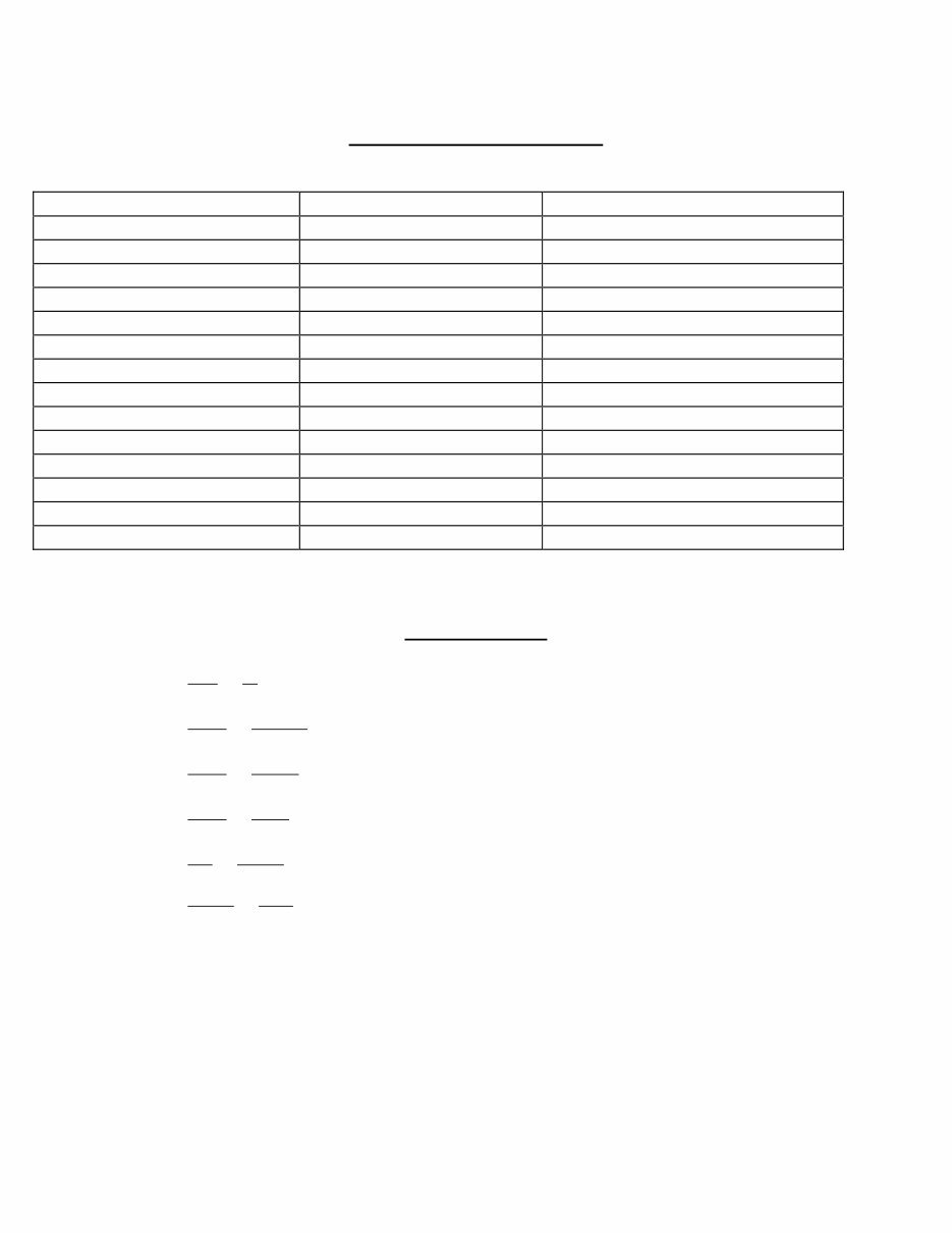
TORQUE SPECIFICATIONS
Metric (in repair manual) US Equivalent Location on Bike
29 to 33 Nm 22 ft/lb. to 30 ft/lb. cylinder heads
22 to 25 kgf-m 175 ft/lb. to 185 ft/lb. fly wheel tightening screws
3.8 to 4.2 kgf-m 30 ft/lb. to 40 ft/lb. cylinder
2.1 to 3.0 kgf-m top 14 ft/lb. to 22 ft/lb. shock absorber
3.6 to 5.0 kgf-m bottom 28 ft/lb. to 36 ft/lb. shock absorber
3.0 to 3.4 kgf-m 22 ft/lb. to 26 ft/lb. bearing nut
3.0 to 3-4 kgf-m 22 ft/lb. to 26 ft/lb. final drive to swing arm bolts
1.6 to 1.8 kgf-m 12 ft/lb. to 14 ft/lb. oil pump bolt
.8 to 1.0 kgf-m 5 ft/lb. to 8 ft/lb. engine sump
1.4 to 1.8 kgf-m 10 ft/lb. to 14 ft/lb. final drive case nuts
7 to 9 kgf-m 50 ft/lb. to 66 ft/lb. nut fastening the pinion bearing
2.2 to 2.8 kgf-m 16 ft/lb. to 20 ft/lb. reverse gear brake lever
1.8 to 2.0 kgf-m 14 ft/lb. to 16 ft/lb. generator gear nut
14.0 to 16.8 kgf-m 100 ft/lb to 120 ft/lb steering stem nut
CONVERSIONS
To convert from mm to in , divide by 25.4 (there are 25.4 mm per inch).
To convert from liters to gallons , divide by 3.785 (there are 3.78 liters per gallon).
To convert from liters to quarts , multiply by 1.056 (there are 1.056 quarts per liter).
To convert from liters to pints , multiply by 2.112 (there are 2.112 pints per liter).
To convert from km to miles , multiply by .62 (there is .62 mile per km).
To convert from km/hr to mph , multiply by .62.
To convert from Newton-meter (Nm) to inch-pound, multiply by 8.86.
To convert from cm
3
(cc) to pints, divide by 473 (there are 473 cc per pint).
To convert Celsius to Fahrenheit, F° = C° x 1.8 = 32°.
To convert Fahrenheit to Celsius,C ° = (F° - 32° ) divided by 1.8
You're Reading a Preview
What's Included?
Fast Download Speeds
Online & Offline Access
Access PDF Contents & Bookmarks
Full Search Facility
Print one or all pages of your manual
$40.99
Ural Tourist 649cc Motorcycle Service Repair Shop Manual
Viewed 24 Times Today

What's Included?
Fast Download Speeds
Online & Offline Access
Access PDF Contents & Bookmarks
Full Search Facility
Print one or all pages of your manual
$40.99

Secure transaction
What's Included?
Fast Download Speeds
Online & Offline Access
Access PDF Contents & Bookmarks
Full Search Facility
Print one or all pages of your manual
Description
The Ural Tourist 649cc Motorcycle Service Repair Shop Manual is a comprehensive guide designed for both professional mechanics and DIY enthusiasts. It provides detailed instructions, wiring diagrams, and pictures to facilitate easy repair jobs. The manual covers all servicing and repair tasks, including routine maintenance.
The manual is available in English and is compatible with Win/MAC/Linux systems. It can be instantly accessed without any shipping costs, making it convenient for immediate use on PC, tablet, or laptop.
Frequently Asked Questions:
- Why should I purchase this manual?
This manual features an easy-to-follow layout covering repair procedures in great detail, enhancing your understanding of parts and repair processes. It empowers you to perform your own servicing, maintenance, and repairs. - What models are covered in this manual?
All models for the specified years and engine types are included. - What type of information is covered?
The manual encompasses all aspects of service, repair, and maintenance. - How long for delivery?
Instant delivery upon payment via Credit/Debit/Paypal Account, eliminating the need for shipping. Start your repair today! - How much money will I save?
This manual can potentially save you thousands of dollars by enabling you to undertake tasks yourself, preventing overcharging by professionals for simple jobs. - Is this Manual hard to use?
No, it is user-friendly and compatible with any PC/MAC computer.


