

2007-2011 Triumph Tiger 1050 Service & Repair Manual
What's Included?
Fast Download Speeds
Online & Offline Access
Access PDF Contents & Bookmarks
Full Search Facility
Print one or all pages of your manual

U H Mp
TIGER
TIGER (ABS)
Part Number 385736S Issue 1, 11.2006
UMW
Service. Manual - Tiger
Table of Contents
pT1IIIIbiIl
Service Manual - Tiger iii
t1 rTii i.iii
Table oof Contents
Howto use this manual ......................................................................iv
Warnings, Cautions and Notes ................................................................. iv
Tamperingwith Noise Control System Prohibited ................................................ v
References................................................................................. v
Dimensions...........................................................................v
Re
p
airsand
Replacements.. . .. . . .. ... ....... .............. ............................v
Force••••••••••• ♦••••...••••.•••••••..•.••••.••.•.•.••.. ..••••.•••••••••••••••••••••••V
Edges• ............................................................................. v
Tighteningprocedures .................................................................v
TRJUMPON
Service Manual - Tiger V
1 1
rrr .i
This manual is designed primarily for use by trained
technicians in a properly equipped workshop. However, it
contains enough detail and basic information to make it
useful to the owner who desires to perform his own basic
maintenance and repair work. The work can only be
carried out if the owner has the necessa ry hand and
special service tools to complete the job.
A basic knowledge of mechanics, including the proper use
of tools and workshop procedures is necessa ry in order to
carry out maintenance and repair work satisfactorily.
Whenever the owner has insufficient experience or doubts
his ability to do the work, an authorised Triumph dealer
must undertake all adjustments, maintenance, and repair
work.
In order to perform the work efficiently and to avoid costly
mistakes, read the text and thoroughly familiarise yourself
with procedures before starting work.
All work should be performed with great care and in a
clean working area with adequate lighting.
Always use the correct special service tools or equipment
specified. Under no circumstances use makeshift tools or
equipment since the use of substitutes may adversely
affect safe operation.
Where accurate measurements are required, they can
only be made using calibrated, precision instruments.
For the duration of the warranty period, an authorised
Triumph dealer must perform all repairs and scheduled
maintenance.
To maximise the life of your Motorcycle:
• Accurately follow the maintenance
requirements of the periodic maintenance
chart in the service manual.
• Do not allow problems to develop.
Investigate unusual noises and changes in the
riding characteristics of the motorcy cl e.
Rectify all problems as soon as possible
(i mmediately if safety related).
• Use only genuine Triumph parts as listed in
the parts catalogue/parts microfiche.
• Follow the procedures in this manual
carefully and completely. Do not take short
cuts.
• Keep complete records of all maintenance
and repairs with dates and any new parts
installed.
• Use only approved lub ri cants, as specified in
the owner's handbook, in the maintenance of
the motorcycle.
To assist in the use of this manual, the section title is given
at the top.
Each major section starts with a contents page, listing the
information contained in the section.
The individual steps comprising repair operations are to
be followed in the sequence in which they appear.
Adjustment and repair operations include reference to
service tool numbers and the associated illustration depicts
the tool.
Where usage is not obvious, the tool is shown in use.
Adjustment and repair operations also in cl ude reference
to wear limits, relevant data, torque figures, specialist
information and useful assembly details.
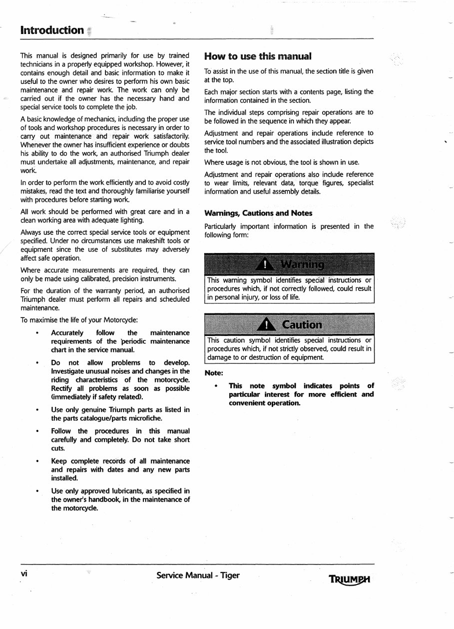
Warnings, Cautions and Notes
Particularly important information is presented in the
following form:
This warning symbol identifies special instructions or
procedures which, if not correctly followed, could result
in personal inju ry, or loss of life.
t.^ ^..^.v ; ^1.X';.;r. :1s.: ..X ,a::i{: .,'` :',:.Y.•<:,.
n:W ^ ,+'^ i:;++'h d:4fwc::? ?f .'i:t 1
::
;
A
^ , ;
}
: a3: },' ^i
^:? s^+ ru .w,q
:{:., 'r. ^.: ^ ^.^ , .} n.. .+y, : n
t:
•
v: '
•
v.: a •. i
fi...
V:
, '" t•
•
:•^;.tia.s'szr{::,v^; •?'• ` `
^{,}^: £^... ' : . t t' ^ +X.
^.:' $$ is
:.3T.% ^ `., it ^: `' : J +
ifi.
Y!
§ £x. :fi•,.. to >X ^:n..,•,a V ^w. • :3;'+'+ J: ,.
N
.^.
f
^.^<'^t`, 2G' ^"
^
^.:;^.4..., ^ ^^r, a.a:. «,,t:#...ah: ''t :.4......,. '^... ^', :1§.
: +5 r.., ^ay^fi•.. ..::^,
>
^^ n +a
This caution symbol identifies special instructions or
procedures which, if not strictly observed, could result in
damage to or destruction of equipment.
Note:
• This note symbol indicates points of
particular interest for more efficient and
convenient operation.
vi
Service Manual - Tiger •
Tampering with Noise Control
system Prohibited
Owners are warned that the law may prohibit:
Edges
Watch for sharp edges,
disassembly and assembly.
industrial quality gloves.
especially during engine
Protect the hands with
a) The removal or rendering inoperative by any
person other than for purposes of maintenance,
repair or replacement, of any device or element of
design incorporated into any new vehicle for the
purpose of noise control prior to its sale or delivery
to the ultimate purchaser or while it is in use; and
b) the use of the vehicle after such device or element
ofdesign has been removed or rendered
inoperative by any person.
References to the left-hand or right-hand side given in this
manual are made when viewing the motorcycle from the
rear.
Operations covered in this manual do not always include
reference to testing the motorcycle after repair. It is
essential that work is inspected and tested after
completion and if necessary a road test of the motorcycle
is carried out particularly where safety related items are
concerned.
The dimensions quoted are to design engineering
specification with service limits where applicable.
During the period of running-in from new, certain
adjustments may vary from the specification figures given
in this manual. These will be reset by the dealer at the
500 mile/800 km service, and thereafter should be
maintained at the figures specified in this manual.
Repairs and Replacements
Before removal and disassembly, thoroughly clean the
motorcycle. Any dirt entering the engine or other parts
will work as an abrasive and shorten the life of the
motorcycle. Particular attention should be paid when
installing a new part, that any dust or metal filings are
cleared from the immediate area.
Force
Common sense should dictate how much force is
necessary in assembly and disassembly. If a part seems
especially difficult to remove or install, stop and examine
what may be causing the problem. Never lever a
component as this will cause damage both to the
component itself and to the surface being levered against.
Whenever tapping to aid removal of an item is necessary,
tap lightly using a hide or plastic faced mallet.
When replacement parts are required, it is essential that
only genuine Triumph parts are used.
Safety features and corrosion prevention treatments
embodied in the motorcycle may be impaired if other
than genuine Triumph parts are fitted. In certain territories,
legislation prohibits the fitting of parts not to the
manufacturer's specification.
Tightening Procedures
Generally, when installing a part with several bolts, nuts or
screws, they should all be started in their holes and
tightened to a snug fit, evenly and in a cross pattern. This
is to avoid distortion of the part and/or causing gas or oil
leakage. Conversely, bolts, nuts, or screws, should all be
loosened (in sequence if specified) by about a quarter of a
turn and then removed.
Where there is a tightening sequence specified in this
Service Manual, the bolts, nuts, or screws must be
tightened in the order and by the method indicated.
Torque wrench setting figures given in this Manual must
be observed. The torque tools used must be of accurate
calibration.
Locking devices, where specified, must be fitted. If the
efficiency of a locking device is impaired during removal it
must be renewed. This applies particularly to micro-
encapsulated fixings which must always be replaced if
disturbed. Where necessary, the text in this manual will
indicate where such a fixing is used.
Twumm
Service Manual - Tiger VI'

fl h.Ii
This page intentionally left blank
V
ile
Service Manual - Tiger
UP
[Lci ir i I TI11MI'I1i
^^ .^ P':
^
X11 ^ ^
Y
'w
IgnitionSystem Safety Precautions ........................................................... 1.3
DangerousSubstances ..................................................................... 1.3
Fluoroelastomers.......................................................................... 1.3
Oils..................................................................................... 1.3
Health Protection Precautions ............................................................... 1.3
EnvironmentalProtection Precautions ........................................................ 1.4
Brakes................................................................................... 1.4
Safet
yInstructions
......................................................................... 1.5
Jacking and Lifting .................................................................... 1.5
Precautionsagainst Damage ........................................................... 1.5
Coolant .............................................. 0 .......................... 0 ... 1.5
Cleaningcomponents ................................................................. 1.6
Lubrication........................................... 0 ..................... 0 ........ 1.6
Joints and Joint Faces ..................................... 0 ........................... 1.6
Gaskets, O- ri ngs ................................................. 0 ................... 0 1.6
Liquidgasket, Non-permanent Locking Agent ............................................ 1.6
ScrewThreads ........................................................0.............. 1.6
Locking Devices ...................................................................... 1.7
Fittin
g
a
Split Pin ..................................................................... 1.7
Circlips, Retaining Rings .......................................... 0 .............. 0 ..... 1.7
Self Locking Nuts ...............................................0..................... 1.7
Encapsulated Bolt ..................................................................... 1.7
Oil and Grease Seals . . . . . . . . . . . . . . . . . . . . . . . . . . . . . . . . . . . . . . . . . . . . . . . . . . . . . . . . . . . . . . . . . .
1
1.7
Press. . . . . . . . . . . . . . . . . . . . . . . . . . . . . . . . . . . . .-... . . . . . . . . . . . . . . . . . . . . . . . . . . . . . . . . . . . . . . . . . 7
BallBearing .......................................... 0 ............................... 1.7
FuelHandling Precautions .................................................................. 1.7
General.. ............................................................................ 1.7
Petrol - Gasoline ...........................................0.......................... 1.8
FuelTank Removal .......... ...... ... .... ... .................................. .... .... 1.8
Chassis Repairs .... . . . . .. . . . 1.8 0 ........................ 1.8
Electrical Precautions ...................................................................... 1.9
BatteryDisconnecting ................................................................. 1.9
Disciplines..................................................................... 0 ..... 1.9
Electrical Wires ................................................... 0 .................. 1.10
Manual Service M l -Ti9er
1.1
uP
General Information
ElectricalTesting ......................................................................... 1.10
BasicElectrical Circuits ......................... . ......................................1.10
CircuitDiagrams ......................................................................... 1.11
Glossaryof Circuit Diagram Symbols ........................................................ 1.11
TracingCircuits .......................................................................... 1.12
ToCheck Continuity :................................................................. 1.13
ToMeasure Voltage :................................................................. 1.13
CAN(Controller Area Networking) ......................................................... 1.14
Alternator/Charging System ............................................................... 1.15
StartingCircuit .......................................................................... 1.16
GeneralFault Finding - Starter Motor and Rela .............................................. 1.16
Inspection......... . ... . . . ........ .................................................. 1.18
Replacement Parts . . 1.18 1.18
ServiceData ........................................................................ 1.18
Specification........................................................................ 1.18
ServiceTools and Garage Equipment ......................... ................................ 1.19
SpecialService Tools ................................................................. 1.19
Full Specification.. 1.24 1.24
TorqueWrench Settings .................................................................... 1.31
CylinderHead Area .................................................................. 1.31
Clutch
..
.
,
1.31
Balancer, Crankshaft and Crankcase .................................................... 1.31
EngineCovers ...................................................................... 1.3 2
Transmission........................................................................ 1.32
LubricationSystem .................................................................. 1.32
FinalDrive .......................................................................... 1.33
CoolingSystem ..................................................................... 1.33
FuelSystem,
Suspension..... .........
System and Airbox ................................................
34 1
1.33
Rear . . . . . . . . . . . . . . . . . . . . . . . . . . . . . . . . . . . . . . . .. . . . . . . . . . . . . . . . . . . . . . . . .-. . . .
FrontSuspension .................................................................... 1.34
Wheels............................................. ...............0000....,..000.6 1.34
FrontBrakes ........................................................................ 1.35
RearBrakes ...............................................I......................... 1.35
ABS System ........................................................................ 1.35
Footrests, Control Plates and Engine Mountings ............ . ............................. 1.36
Electrical............... . ......................................................... . . 1.36
Bodywork.......................................................................... 1.36
ThrottleCable Routing ............................. ..............................0 0 0 0 ...... 1.37
ClutchCable Routing...... ................................................................. 1.38
Fuel Tank Breather Hose Routing - Models without Evaporative Emissions ........................ 1.39
Fuel Tank Breather Hose Routing - Models without Evaporative Emissions ........................ 1.40
Mainwiring Harness Routing .............................................................. 1.41
FrontBrake Hose Routing - Models without ABS Brakes ........................................ 1.42
Rear Brake Hose Routing - Models without ABS Brakes ........................................ 1.43
BrakeHose Routing - Models with ABS Brakes ................................................ 1.44
1.2
Service Manual - Tiger .
uM
jiiiIi'i ii Th
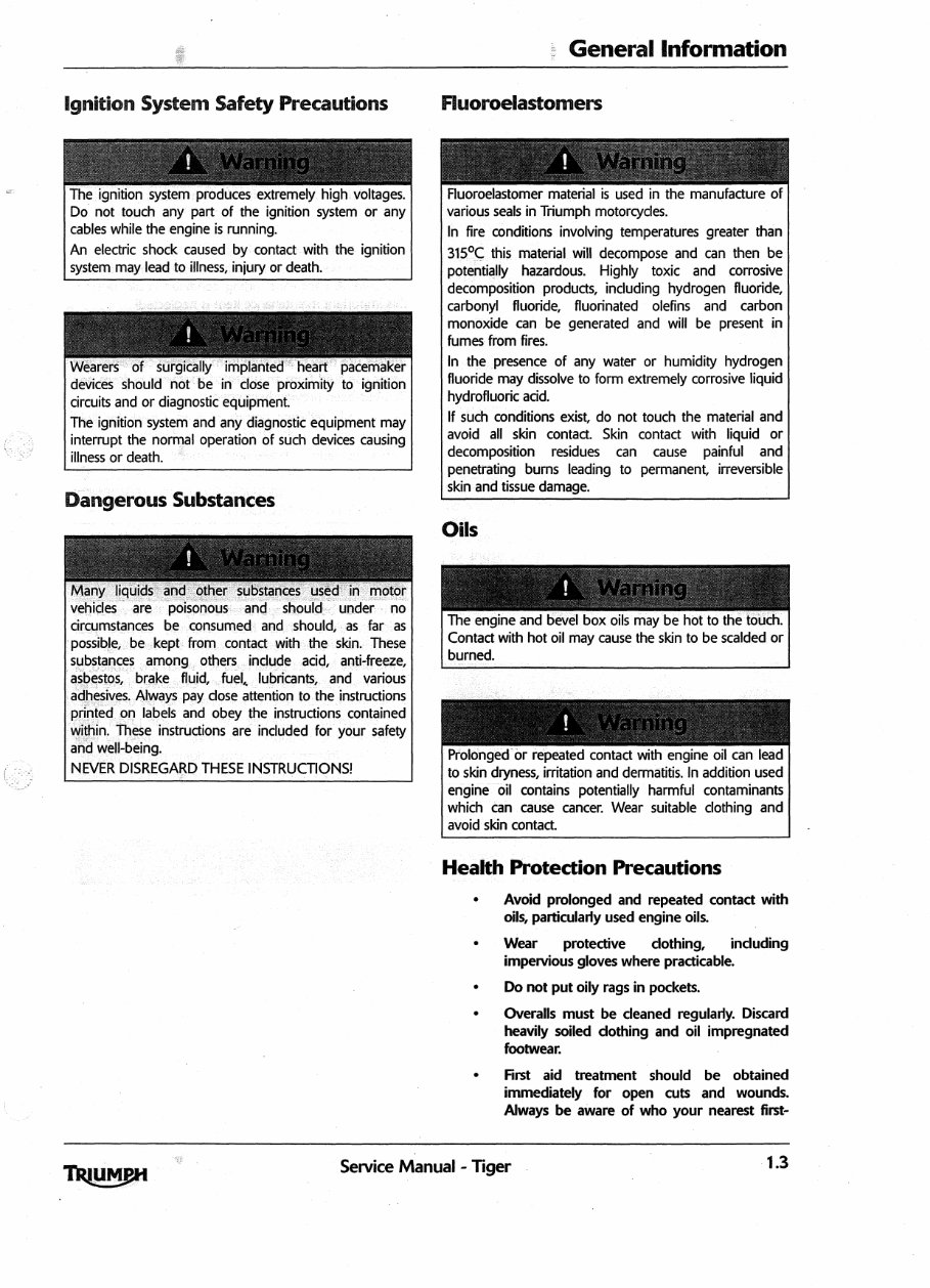
^gf l i ci © ^n System safety Precautions
The ignition system produces extremely high. voltages.
Do not touch any part of the ignition system or any
cables while the engine is running.
An electric shock caused by contact with the ignition
system may lead to illness, inju ry or death.
Wearers of surgically implanted heart pacemaker
devices should not be in close proximity to ignition
circuits and or diagnostic equipment.
The ignition system and any diagnostic equipment may
interrupt the normal operation of such devices causing
illness or death.
Many liquids and other substances used in motor
vehicles are poisonous and should under no
circumstances be consumed and should, as far as
. possible, be kept from contact with the skin. These
substances among others include acid, anti-freeze,
asbestos, brake fluid, fuel., lubricants, and various
adhesives. Always pay dose attention to the instructions
printed on labels and obey the instructions contained
within. These instructions are included for your safety
and well-being.
NEVER DISREGARD THESE INSTRUCTIONS!
Health Protection Precautions
• Avoid p rolonged and re peated contact with
oils, particularly used engine oils..
• Wear protective cl othing, including
i mpervious gloves where practicable.
• Do not put oily rags in pockets.
• Overalls must be cl eaned regularly. Discard
heavily soiled clothing and oil impregnated
footwear.
• Fi rst aid treatment should be obtained
i mmediately for open cuts and wounds.
Always be aware of who your nearest first-
Prolonged or repeated contact with engine oil can lead
to skin dryness, irritation and dermatitis. In addition used
engine oil contains potentially harmful contaminants
which can cause cancer. Wear suitable clothing and
avoid skin contact.
U
Service Manual - Tiger 1.3
You're Reading a Preview
What's Included?
Fast Download Speeds
Online & Offline Access
Access PDF Contents & Bookmarks
Full Search Facility
Print one or all pages of your manual
$28.99
$37.99
Viewed 49 Times Today


Secure transaction
What's Included?
Fast Download Speeds
Online & Offline Access
Access PDF Contents & Bookmarks
Full Search Facility
Print one or all pages of your manual
$28.99
$37.99
Get access to a comprehensive repair manual for the Triumph Tiger 1050 manufactured between 2007 and 2011. Our manuals contain all the necessary and up-to-date information required for the repair and maintenance of this vehicle. Whether you are a professional mechanic or a DIY enthusiast, these manuals are an invaluable resource for keeping your Triumph Tiger 1050 in top condition.


