

SERVICE MANUAL
FORWARD
HOW TO USE THIS
MANUAL
CONTENTS

FORWARD
This service manual contains the technical data of each component inspection
and repair for the Sanyang JOYRIDE 125/150/200 motorcycle. The manual is
shown with illustrations and focused on “Service Procedures”, “Operation Key
Points”, and “Inspection Adjustment” so that provides technician with service
guidelines.
If the style and construction of the motorcycle, JOYRIDE 125/150/200, are
different from that of the photos, pictures shown in this manual, the actual
vehicle shall prevail. Specifications are subject to change without notice.
Service Department
Sanyang Industry Co., LTD.
Homepage Contents

How to Use This Manual
This service manual describes basic information of different system parts and
system inspection & service for Sanyang JOYRIDE 125/150/200 motorcycles.
In addition, please refer to the manual contents in detailed for the model you
serviced in inspection and adjustment.
The first chapter covers general information and trouble diagnosis.
The second chapter covers service maintenance information.
Th third to the tenth chapters cover engine and driving systems.
The eleventh to the fourteenth is contained the parts set of assembly body.
The fifteenth chapter is electrical equipment.
The sixteenth chapter is emission control system.
The seventeenth chapter is wiring diagram
Please see index of content for quick having the special parts and system
information.
There are link devices in the “H9A CONTENTS” file. Just only click on the
icon and it will link to the article what you want to see.
All information, illustration, directions and specifications included in this manual
are current as at the time of publication. Sanyang reserves the rights to make
changes at any time without prior notice and without incurring any obligation
whatever. Without written consent by Sangang can not copy any part of this
manual.
Homepage Contents
CONTENTS
Page Content Index
1-1 ~ 1-16 GENERAL INFORMATION 1
2-1 ~ 2-12 MAINTENANCE INFORMATION 2
3-1 ~ 3-6 LUBRICATION SYSTEM 3
4-1 ~ 4-9 FUEL SYSTEM 4
5-1 ~ 5-6 ENGINE REMOVAL 5
6-1 ~ 6-14 CYLINDER HEAD/VALVE 6
7-1 ~ 7-8 CYLINDER/PISTON 7
8-1 ~ 8-14 V-BELT DRIVING SYSTEM/FOOT STARTER 8
9-1 ~ 9-8 FINAL DRIVING MECHANISM 9
10-1 ~ 10-6 ALTERNATOR/STARTING CLUTCH 10
11-1 ~ 11-8 CRANKSHAFT/CRANKCASE 11
12-1 ~ 12-11 COOLING SYSTEM 12
13-1 ~ 13-13 BODY COVERS 13
14-1 ~ 14-10 BRAKE 14
15-1 ~ 15-12 STEERING/FRONT WHEEL/FRONT BRAKE/
FRONT CUSHION
15
16-1 ~ 16-5 REAR WHEEL/REAR BRAKE/REAR CUSHION 16
17-1 ~ 17-18 ELECTRICAL SYSTEM 17
18-1 ~ 18-10 SPECIL TOOLS 18
19-1 ~ 19-2 WIRING DIAGRAM 18
Homepage Contents
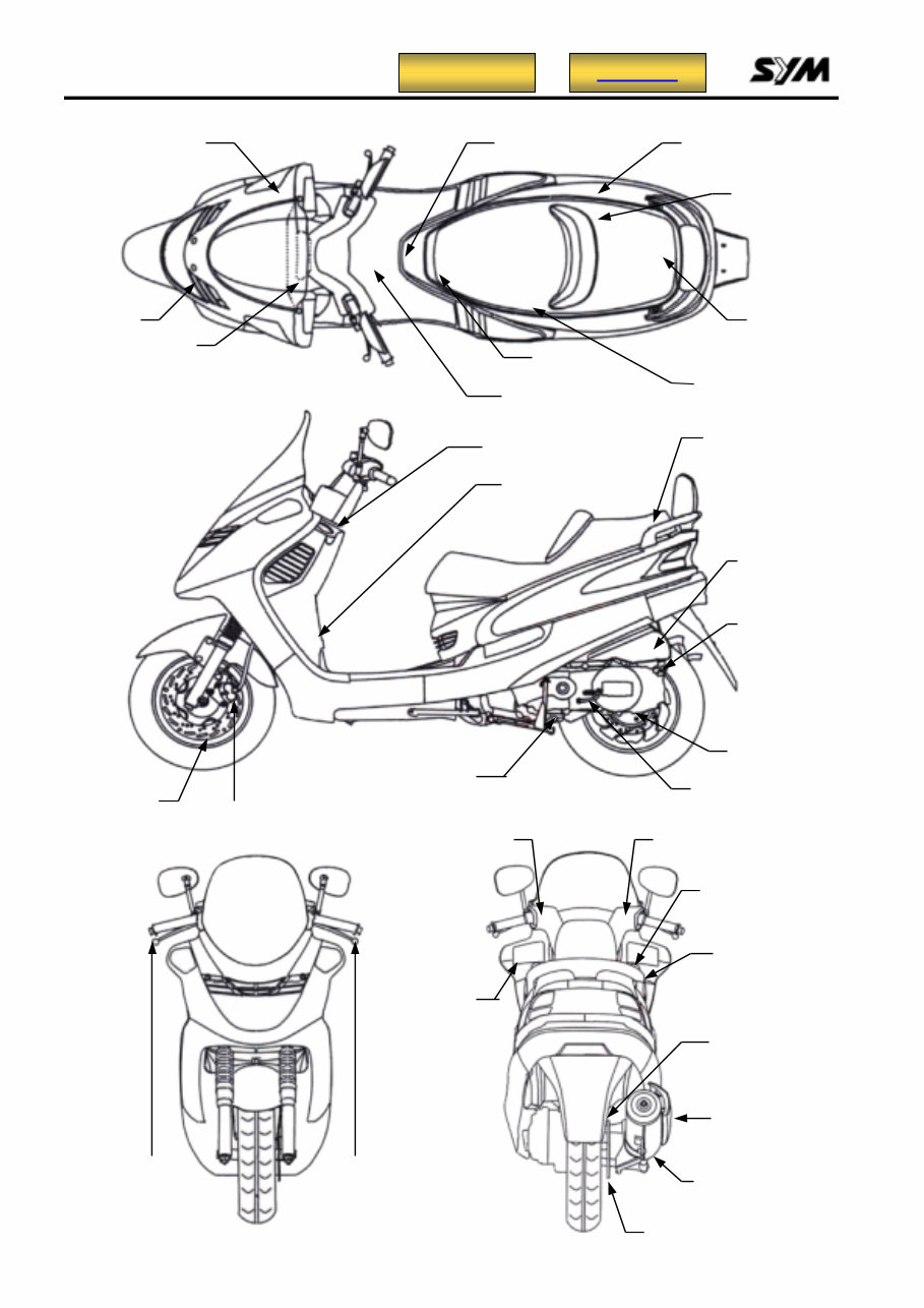
MODEL ILLUSTRATION
Winker relay
Radiator
Fuel tank cap
Spark plug
Front brake disk
Engine number
ENG. Oil drain plug
Kick starter pedal
Engine stop /Light /
Starter switch
High & Low beam /
Passing / Turn signal /
Horn switch
Muffler
Reserved tank
cap
Coolant filler
cap
Ignition / Seat open
switch
Fuses / C.D.I.
Gear oil
drain plug
REG/REC.
Start MAG. switch
Battery
IG. coil
Horn
Fuel tank
Fuel pump
Frame number
Oil level
Oil strainer
Water pump
Seat catch A
Seat catch B
Front brake
caliper
Rear brake
disk
Rear brake
caliper
Front brake Rear brake
Homepage Contents
1. GENERAL INFORMATION
1-1
Symbols and marks………………….1-1 Torque values……………………….1-8
General safety…………………………1-2 Cables and harness routing………1-10
Service precautions………………….1-3 Troubleshooting…………………….1-11
Specifications…………………………1-5 Lubrication points…………………..1-15
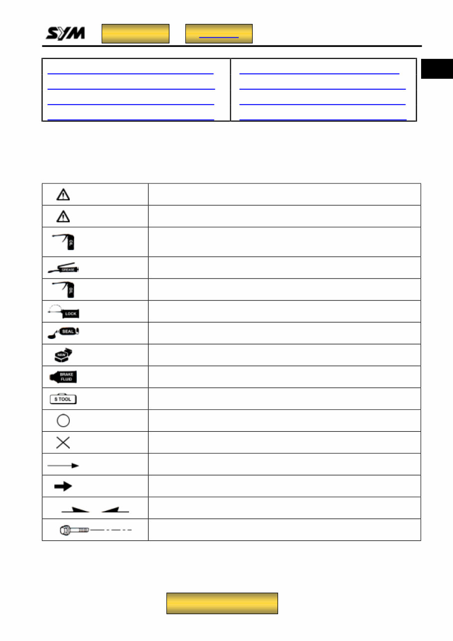
Symbols and Marks
Symbols and marks are used in this manual to indicate what and where the special service are
needed, in case supplemental information is procedures needed for these symbols and marks,
explanations will be added to the text instead of using the symbols or marks.
Warning
Means that serious injury or even death may result if procedures are not
followed.
Caution
Means that equipment damages may result if procedures are not
followed.
Engine oil
Limits to use SAE 20 JASO FC class oil. Warranty will not cover the
damage that caused by not apply with the limited engine oil.
(Recommended oil: MAX-2 serial oils)
Grease King Mate G-3 is recommended.
Gear oil
King Mate gear oil serials are recommended. (Bramax HYPOID GEAR
OIL # 140)
Locking sealant
Apply sealant, medium strength sealant should be used unless
otherwise specified.
Oil seal Apply with lubricant.
Renew Replace with a new part before installation.
Brake fluid Use recommended brake fluid DOT3 or WELLRUN brake fluid.
Special tools Special tools.
correct Meaning correct installation.
wrong Meaning wrong installation.
Indication Indication of components.
directions Indicates position and operation directions.
Components assembly directions each other.
Indicates where the bolt installation direction, --- means that bolt cross
through the component (invisibility).
1
Homepage Contents
To this chapter contents
1. GENERAL INFORMATION
1-2
General safety
Carbon monoxide
If you must run your engine, ensure the place is
well ventilated. Never run your engine in a
closed area. Run your engine in an open area, if
you have to run your engine in a closed area, be
sure to use an extractor.
Caution
Gasoline
Gasoline is a low ignition point and explosive
material. Work in a well-ventilated place, no
flame or spark should be allowed in the work
place or where gasoline is being stored.
Caution
Used engine oil
Caution
Hot components
Caution
Battery
Caution
Brake shoe
Do not use an air hose or a dry brush to clean
components of the brake system, use a vacuum
cleaner or the equivalent to avoid dust flying.
Caution
Brake fluid
Caution
Exhaust contains toxic gas which may cause
one to lose consciousness and even result in
death.
•Battery emits explosive gases; flame is
strictly prohibited. Keep the place well
ventilated when charging the battery.
•Battery contains sulfuric acid (electrolyte)
which can cause serious burns so be
careful do not be spray on your eyes or
skin. If you get battery acid on your skin,
flush it off immediately with water. If you
get battery acid in your eyes, flush it off
immediately with water and then go to
hospital to see an ophthalmologist.
•If you swallow it by mistake, drink a lot of
water or milk, and take some laxative such
as castor oil or vegetable oil and then go to
see a doctor.
•Keep electrolyte beyond reach of children.
Gasoline is highly flammable, and may
explode under some conditions, keep it away
from children.
Prolonged contact with used engine oil (or
transmission oil) may cause skin cancer
although it might not be verified.
We recommend that you wash your hands
with soap and water right after contacting.
Keep the used oil beyond reach of children.
Inhaling brake shoe or pad ash may cause
disorders and cancer of the breathing system.
Spilling brake fluid on painted, plastic, or
rubber parts may cause damage to the parts.
Place a clean towel on the above-mentioned
parts for protection when servicing the brake
system. Keep the brake fluid beyond reach of
children.
Components of the engine and exhaust
system can become extremely hot after
engine running. They remain very hot even
after the engine has been stopped for some
time. When performing service work on these
parts, wear insulated gloves and wait until
cooling off.
To this chapter contents
1. GENERAL INFORMATION
1-3
Service Precautions
Always use with Sanyang genuine parts and
recommended oils. Using non-designed parts
for Sanyang motorcycle may damage the
motorcycle.
Special tools are designed for remove and
install of components without damaging the
parts being worked on. Using wrong tools
may result in parts damaged.
When servicing this motorcycle, use only
metric tools. Metric bolts, nuts, and screws
are not interchangeable with the English
system, using wrong tools and fasteners may
damage this vehicle.
Clean the outside of the parts or the cover
before removing it from the motorcycle.
Otherwise, dirt and deposit accumulated on
the part's surface may fall into the engine,
chassis, or brake system to cause a damage.
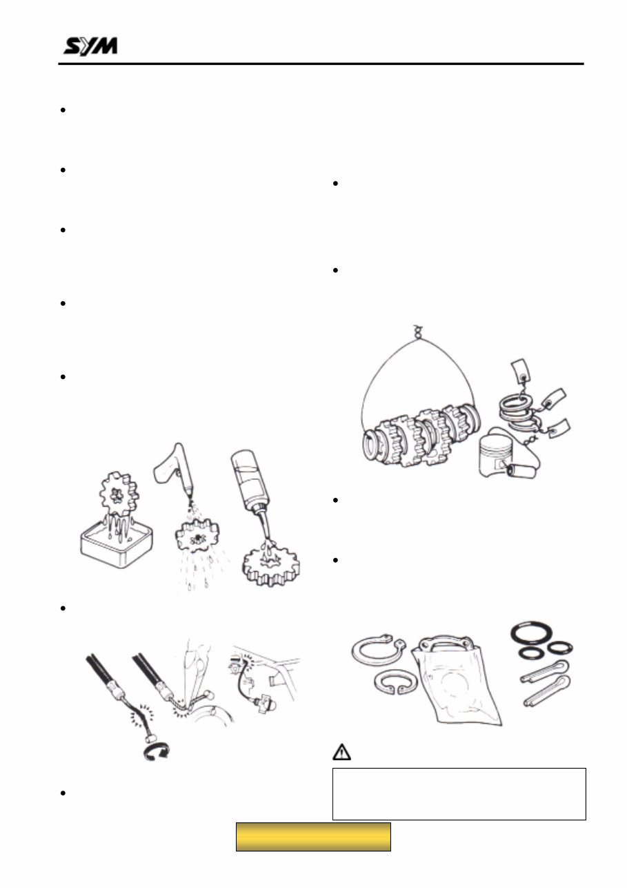
Wash and clean parts with high ignition point
solvent, and blow dry with compressed air.
Pay special attention to O-rings or oil seals
because most cleaning agents have an
adverse effect on them.
Never bend or twist a control cable to prevent
unsmooth control and premature worn out.
Rubber parts may become deteriorated when
old, and prone to be damaged by solvent and
oil. Check these parts before installation to
make sure that they are in good condition,
replace if necessary.
When loosening a component which has
different sized fasteners, operate with a
diagonal pattern and work from inside out.
Loosen the small fasteners first. If the bigger
ones are loosen first, small fasteners may
receive too much stress.
Store complex components such as
transmission parts in the proper assemble
order and tie them together with a wire for
ease of installation later.
Note the reassemble position of the important
components before disassembling them to
ensure they will be reassembled in correct
dimensions (depth, distance or position).
Components not to be reused should be
replaced when disassembled including
gaskets metal seal rings, O-rings, oil seals,
snap rings, and split pins.
Caution
In addition to damaging paint finish, brake oil
can also damage the structural integration of
plastic or rubber parts.
To this chapter contents
1. GENERAL INFORMATION
1-4
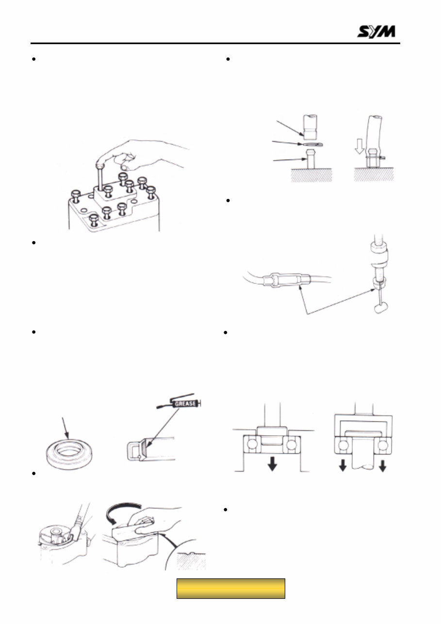
The length of bolts and screws for assemblies,
cover plates or boxes is different from one
another, be sure they are correctly installed.
In case of confusion, Insert the bolt into the
hole to compare its length with other bolts, if
its length out side the hole is the same with
other bolts, it is a correct bolt. Bolts for the
same assembly should have the same length.
Tighten assemblies with different dimension
fasteners as follows: Tighten all the fasteners
with fingers, then tighten the big ones with
special tool first diagonally from inside toward
outside, important components should be
tightened 2 to 3 times with appropriate
increments to avoid warp unless otherwise
indicated. Bolts and fasteners should be kept
clean and dry. Do not apply oil to the threads.
When oil seal is installed, fill the groove with
grease, install the oil seal with the name of
the manufacturer facing outside, check the
shaft on which the oil seal is to be installed for
smoothness and for burrs that may damage
the oil seal.
Remove residues of the old gasket or sealant
before reinstallation, grind with a grindstone if
the contact surface has any damage.
The ends of rubber hoses (for fuel, vacuum,
or coolant) should be pushed as far as they
can go to their connections so that there is
enough room below the enlarged ends for
tightening the clamps.
Rubber and plastic boots should be properly
reinstalled to the original correct positions as
designed.
The tool should be pressed against two (inner
and outer) bearing races when removing a
ball bearing. Damage may result if the tool is
pressed against only one race (either inner
race or outer race). In this case, the bearing
should be replaced. To avoid damaging the
bearing, use equal force on both races.
Both of these examples can result in bearing damage.
Lubricate the rotation face as assembling.
Check if positions and operation for installed
parts is in correct and properly.
Manufacturer's
name
Groove
Clamp
Connection
Boots
To this chapter contents
1. GENERAL INFORMATION
1-5
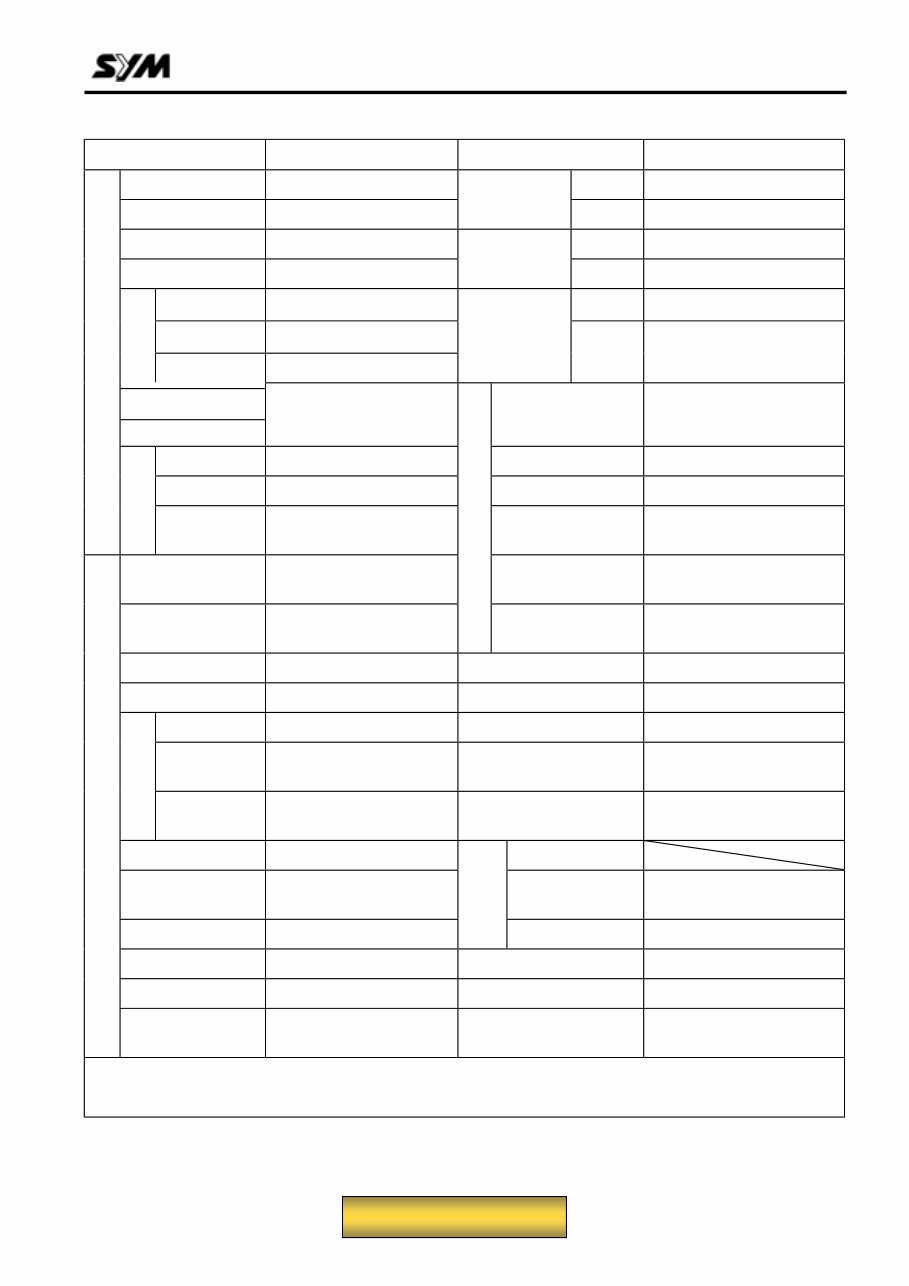
Specifications
Make SANYANG MODEL LA12W
Overall Length 2010 mm Front TELESCOPIC FORK
Overall Width 760 mm
Suspension
System
Rear UnlT SWING
Overall Height 1155 mm Front 110 / 80-12 61L
Wheel Base 1440 mm
Tire
Specifications
Rear 130 / 70-12 64L
Front 55 kg Front DlSK (ψ273mm)
Rear 89 kg
Brake System
Rear DlSK (ψ200mm)
Curb
Weight
Total 144 kg
Passengers/
Weight
Two /110 kg Max. Speed 99 km/hr Above
Front 79 kg Climb Ability 28° above
Rear 175 kg Primary Reduction BELT
WEIGHT DIMENSION
Total Weight
Total 254 kg
Secondary
Reduction
GEAR
Type Gasoline Clutch
3-piece centrifugal, dry
type
Position and
arrangement
Horizontal, below center,
CYL incline 80°
PERFORMANCE
Transmission C.V.T.
Fuel Used >92 Unleaded gasoline Speed meter 0 ~ 140 km/hr
Cycle/Cooling 4-stroke/water cooled Horn 93 – 112 dB/A
Bore Ø 57 mm Muffler Expansion & Pulse Type
Stroke 48.8 mm
Exhaust Pipe Position
and Direction
Right side, and Backward
Cylinder
Number/Arra
ngement
Single Cylinder Lubrication System
Forced pressure and wet
sump
Displacement 124.5 cc Solid Particulate
Compression
Ratio
10.5 : 1 CO 3.5 % ↓
Max. HP 11.4 / 8500 ps/rpm
Exhaust
Concentration
HC Below 2000 ppm
Max. Torque 1.01 / 7000 kg-m/rpm E.E.C. Non-equipped
Ignition C.D.I. P.C.V. Equipped
ENGINE
Starting System Power & Foot
Catalytic reaction
control system
Non-equipped
Remark:
To this chapter contents
You're Reading a Preview
What's Included?
Fast Download Speeds
Online & Offline Access
Access PDF Contents & Bookmarks
Full Search Facility
Print one or all pages of your manual
$31.99
SYM Joyride 125 150 200 Service & Repair Manual
Viewed 35 Times Today

What's Included?
Fast Download Speeds
Online & Offline Access
Access PDF Contents & Bookmarks
Full Search Facility
Print one or all pages of your manual
$31.99

Secure transaction
What's Included?
Fast Download Speeds
Online & Offline Access
Access PDF Contents & Bookmarks
Full Search Facility
Print one or all pages of your manual
Description
- This complete factory service repair workshop manual is available for instant access on your computer, tablet, or smartphone.
- It covers all repairs, servicing, and troubleshooting procedures with detailed photos and diagrams.
- Professional mechanics and technicians use this manual, which contains step-by-step instructions and highly detailed exploded diagrams and pictures.
- You have the option to print out a single page or the entire manual.
- This manual can be used on multiple computers without any limitations or trial periods.
- There is no expiry date or renewal fee; you can use this manual for life.
- It is fully compatible with Windows and MAC computers.
For more information, please click the button below.


