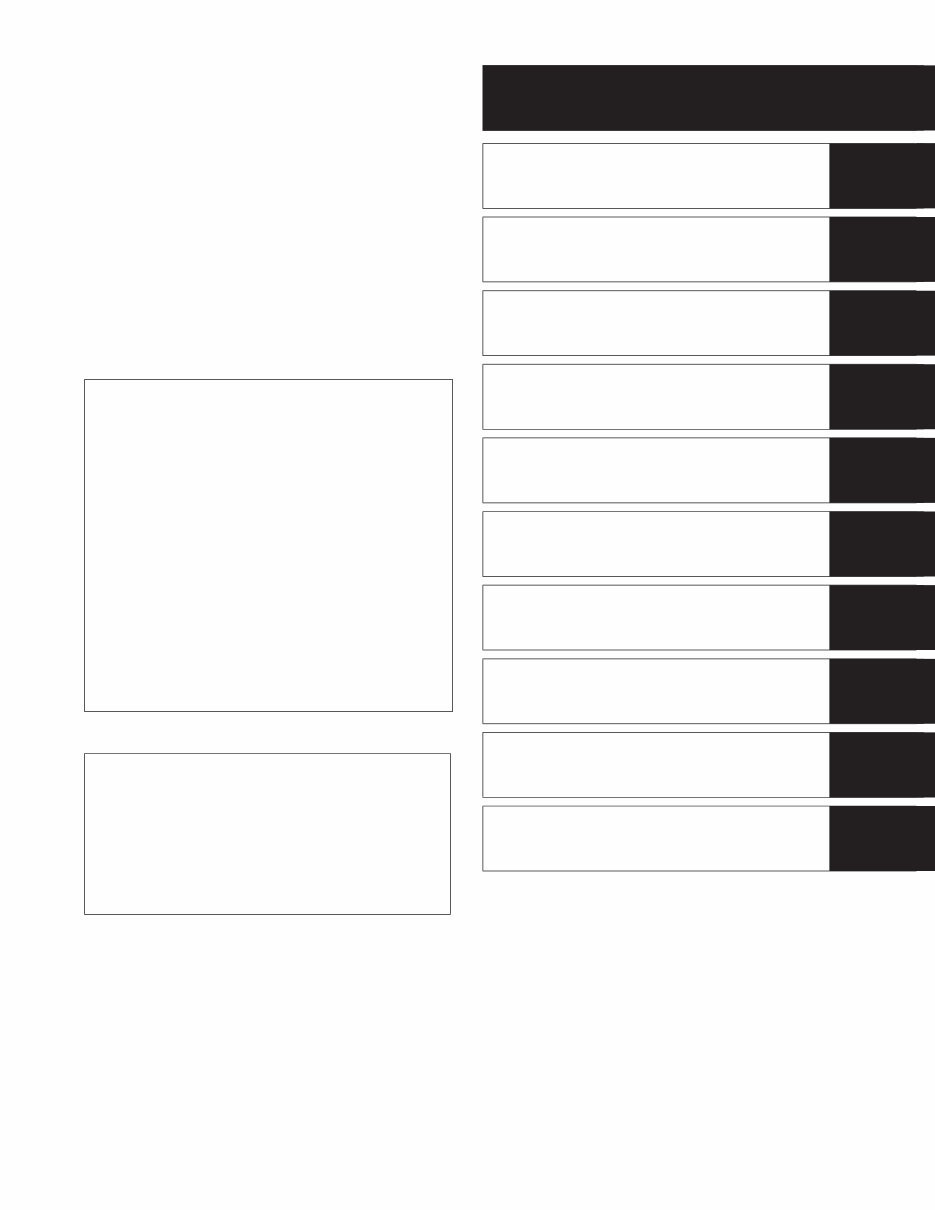
GROUP INDEX GENERAL INFORMATION 1 PERIODIC MAINTENANCE 2 ENGINE 3 FI SYSTEM DIAGNOSIS 4 FUEL SYSTEM AND THROTTLE BODY 5 COOLING AND LUBRICATION SYSTEM 6 CHASSIS 7 ELECTRICAL SYSTEM 8 SERVICING INFORMATION 9 10 FOREWORD This manual contains an introductory description on the SUZUKI DL650 and procedures for its inspec- tion/service and overhaul of its main components. Other information considered as generally known is not included. Read the GENERAL INFORMATION section to familiarize yourself with the motorcycle and its main- tenance. Use this section as well as other sections to use as a guide for proper inspection and service. This manual will help you know the motorcycle bet- ter so that you can assure your customers of fast and reliable service. * This manual has been prepared on the basis of the latest specifications at the time of publi- cation. If modifications have been made since then, differences may exist between the con- tent of this manual and the actual motorcycle. * Illustrations in this manual are used to show the basic principles of operation and work procedures. They may not represent the actual motorcycle exactly in detail. * This manual is written for persons who have enough knowledge, skills and tools, including special tools, for servicing SUZUKI motorcy- cles. If you do not have the proper knowledge and tools, ask your authorized SUZUKI motorcycle dealer to help you. Inexperienced mechanics or mechanics without the proper tools and equipment may not be able to properly perform the services described in this manual. Improper repair may result in injury to the mechanic and may render the motorcycle unsafe for the rider and passenger. EMISSION CONTROL INFORMATION
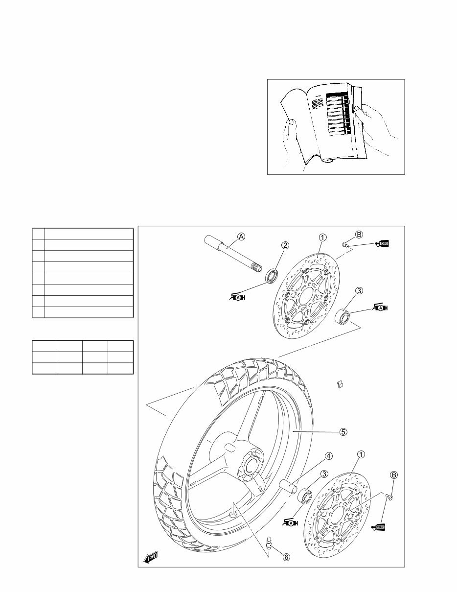
HOW TO USE THIS MANUAL TO LOCATE WHAT YOU ARE LOOKING FOR: 1. The text of this manual is divided into sections. 2. The section titles are listed in the GROUP INDEX. 3. Holding the manual as shown at the right will allow you to find the first page of the section easily. 4. The contents are listed on the first page of each section to help you find the item and page you need. COMPONENT PARTS AND WORK TO BE DONE Under the name of each system or unit, is its exploded view. Work instructions and other service information such as the tightening torque, lubricating points and locking agent points, are provided. Example: Front wheel 1 Brake disc 2 Dust seal 3 Bearing 4 Center spacer 5 Front wheel 6 Tire valve A Front axle B Brake disc bolt " ITEM N·m kgf-m lb-ft A 65 6.5 47.0 B 23 2.3 16.5
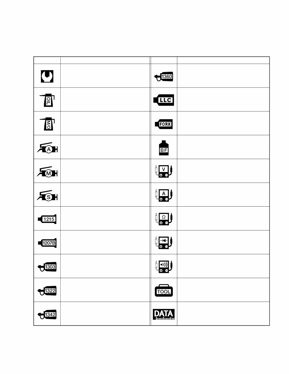
SYMBOL Listed in the table below are the symbols indicating instructions and other information necessary for servic- ing. The meaning of each symbol is also included in the table. SYMBOL DEFINITION SYMBOL DEFINITION Torque control required. Data beside it indicates specified torque. Apply THREAD LOCK SUPER “1360”. 99000-32130 Apply oil. Use engine oil unless other- wise specified. Use engine coolant. Apply molybdenum oil solution. (Mixture of engine oil and SUZUKI MOLY PASTE in a ratio of 1:1) Use fork oil. 99000-99001-SS8 Apply SUZUKI SUPER GREASE “A”. 99000-25030 (USA) 99000-25010 (Others) Apply or use brake fluid. Apply SUZUKI MOLY PASTE. 99000-25140 Measure in voltage range. Apply SUZUKI SILICONE GREASE. 99000-25100 Measure in current range. Apply SUZUKI BOND “1215”. 99000-31110 (Except USA) Measure in resistance range. Apply SUZUKI BOND “1207B”. 99104-31140 (USA) 99000-31140 (Others) Measure in diode test range. Apply THREAD LOCK SUPER “1303”. 99000-32030 Measure in continuity test range. Apply THREAD LOCK SUPER “1322”. 99000-32110 (Except USA) Use special tool. Apply THREAD LOCK “1342”. 99000-32050 Indication of service data.
ABBREVIATIONS USED IN THIS MANUAL A ABDC : After Bottom Dead Center AC : Alternating Current ACL : Air Cleaner, Air Cleaner Box API : American Petroleum Institute ATDC : After Top Dead Center ATM Pressure: Atmospheric Pressure Atmospheric Pressure Sensor (APS) A/F : Air Fuel Mixture B BBDC : Before Bottom Dead Center BTDC : Before Top Dead Center B+ : Battery Positive Voltage C CKP Sensor : Crankshaft Position Sensor (CKPS) CKT : Circuit CLP Switch : Clutch Lever Position Switch (Clutch Switch) CMP Sensor : Camshaft Position Sensor (CMPS) CO : Carbon Monoxide CPU : Central Processing Unit D DC : Direct Current DMC : Dealer Mode Coupler DOHC : Double Over Head Camshaft DRL : Daytime Running Light E ECM : Engine Control Module Engine Control Unit (ECU) (FI Control Unit) ECT Sensor : Engine Coolant Temperature Sensor (ECTS), Water Temp. Sensor (WTS) EVAP : Evaporative Emission EVAP Canister : Evaporative Emission Canister (Canister) F FI : Fuel Injection, Fuel Injector FP : Fuel Pump FPR : Fuel Pressure Regulator FP Relay : Fuel Pump Relay G GEN : Generator GND : Ground GP Switch : Gear Position Switch H HC : Hydrocarbons I IAP Sensor : Intake Air Pressure Sensor (IAPS) IAT Sensor : Intake Air Temperature Sensor (IATS) IG : Ignition L LCD : Liquid Crystal Display LED : Light Emitting Diode (Malfunction Indicator Lamp) LH : Left Hand
M MAL-Code : Malfunction Code (Diagnostic Code) Max : Maximum MIL : Malfunction Indicator Lamp (LED) Min : Minimum N NOx : Nitrogen Oxides O OHC : Over Head Camshaft OPS : Oil Pressure Switch P PCV : Positive Crankcase Ventilation (Crankcase Breather) R RH : Right Hand ROM : Read Only Memory S SAE : Society of Automotive Engineers STC System : Secondary Throttle Control System (STCS) STP Sensor : Secondary Throttle Position Sensor (STPS) ST Valve : Secondary Throttle Valve (STV) STV Actuator : Secondary Throttle Valve Actuator (STVA) T TO Sensor : Tip Over Sensor (TOS) TP Sensor : Throttle Position Sensor (TPS) V VD : Vacuum Damper
SAE-TO-FORMER SUZUKI TERM This table lists SAE (Society of Automotive Engineers) J1930 terms and abbreviations which may be used in this manual in compliance with SAE recommendations, as well as their former SUZUKI names. SAE TERM FORMER SUZUKI TERM FULL TERM ABBREVIATION A Air Cleaner B Barometric Pressure Battery Positive Voltage C Camshaft Position Sensor Crankshaft Position Sensor D Data Link Connector Diagnostic Test Mode Diagnostic Trouble Code E Electronic lgnition Engine Control Module Engine Coolant Level Engine Coolant Temperature Engine Speed Evaporative Emission Evaporative Emission Canister F Fan Control Fuel Level Sensor Fuel Pump G Generator Ground ACL BARO B+ CMP Sensor CKP Sensor DLC DTM DTC EI ECM ECL ECT RPM EVAP EVAP Canister FC ------- FP GEN GND Air Cleaner, Air Cleaner Box Barometric Pressure, Atmospheric Pressure (APS, AP Sensor) Battery Voltage, +B Camshaft Position Sensor (CMPS) Crankshaft Position Sensor (CKPS), Crank Angle Dealer Mode Coupler ------- Diagnostic Code, Malfunction Code ------- Engine Control Module (ECM) FI Control Unit, Engine Control Unit (ECU) Coolant Level Coolant Temperature, Engine Coolant Tem- perature Water Temperature Engine Speed (RPM) Evaporative Emission ------- (Canister) ------- Fuel Level Sensor, Fuel Level Gauge Fuel Pump (FP) Generator Ground (GND, GRD)
SAE TERM FORMER SUZUKI TERM FULL TERM ABBREVIATION I Idle Speed Control Ignition Control Ignition Control Module Intake Air Temperature M Malfunction Indicator Lamp Manifold Absolute Pressure Mass Air Flow O On-Board Diagnostic Open Loop P Programmable Read Only Memory Pulsed Secondary Air Injection Purge Valve R Random Access Memory Read Only Memory S Secondary Air Injection Secondary Throttle Control System Secondary Throttle Valve Secondary Throttle Valve Actuator T Throttle Body Throttle Body Fuel Injection Throttle Position Sensor V Voltage Regulator Volume Air Flow ISC IC ICM IAT MIL MAP MAF OBD OL PROM PAIR Purge Valve RAM ROM AIR STCS STV STVA TB TBI TP Sensor VR VAF ------- Electronic Spark Advance (ESA) ------- Intake Air Temperature (IAT), Air Temperature LED Lamp Malfunction Indicator Lamp (MIL) Intake Air Pressure (IAP), Intake Vacuum Air Flow Self-Diagnosis Function Diagnostic ------- ------- Pulse Air Control (PAIR) Purge Valve (SP Valve) ------- ROM ------- STC System (STCS) ST Valve (STV) STV Actuator (STVA) Throttle Body (TB) Throttle Body Fuel Injection (TBI) TP Sensor (TPS) Voltage Regulator Air Flow
WIRE COLOR B : Black Gr : Gray R : Red Bl : Blue Lbl : Light blue W : White Br : Brown Lg : Light green Y : Yellow Dg : Dark green O : Orange G : Green P : Pink B/Bl : Black with Blue tracer B/Br : Black with Brown tracer B/G : Black with Green tracer B/O : Black with Orange tracer B/R : Black with Red tracer B/W : Black with White tracer B/Y : Black with Yellow tracer Bl/B : Blue with Black tracer Bl/G : Blue with Green tracer Bl/R : Blue with Red tracer Bl/W : Blue with White tracer Bl/Y : Blue with Yellow tracer Br/B : Brown with Black tracer Br/W : Brown with White tracer G/B : Green with Black tracer G/Y : Green with Yellow tracer Gr/B : Gray with Black tracer Gr/R : Gray with Red tracer Gr/W : Gray with White tracer O/B : Orange with Black tracer O/Bl : Orange with Blue tracer O/G : Orange with Green tracer O/R : Orange with Red tracer O/W : Orange with White tracer O/Y : Orange with Yellow tracer P/W : Pink with White tracer R/B : Red with Black tracer R/W : Red with White tracer W/B : White with Black tracer W/Bl : White with Blue tracer W/G : White with Green tracer W/R : White with Red tracer Y/B : Yellow with Black tracer Y/Bl : Yellow with Blue tracer Y/G : Yellow with Green tracer Y/R : Yellow with Red tracer Y/W : Yellow with White tracer
You're Reading a Preview
What's Included?
Lifetime Access
Fast Download Speeds
Online & Offline Access
Access PDF Contents & Bookmarks
Full Search Facility
Print one or all pages of your manual
$37.99
SUZUKI DL650 V STROM Service Repair Manual 2004-2009
This service repair manual is a comprehensive guide containing everything you need for the repair, maintenance, rebuilding, refurbishing, or restoration of your vehicle. It includes hundreds of pages with a superb table of contents covering a wide range of information, such as:
Complete engine service
Fuel system service
Factory repair procedures
Wiring diagrams
Gearbox
Exhaust system
Suspension
Fault finding
Clutch removal and installation
Front suspension
Bodywork
Gearbox service, removal, and installation
Cooling system
Detailed specifications
Transmission
Factory maintenance schedules
Electrics
Engine firing order
Brake servicing procedures
Driveshaft
Timing chain service
Exhaust service
Abundant illustrations
Lots of pictures & diagrams
Plus lots more
This manual covers all diagnostic and repair procedures, providing access to the same information used by professional technicians and mechanics. It offers highly detailed, printable diagrams, allowing for easy access to the necessary information without the hassle of worn-out or messy manuals. The manual is designed for both professional mechanics and DIY enthusiasts, ensuring ease of use without requiring special technical knowledge.
Upon secure payment completion, you will receive instant delivery of this service repair manual, compatible with all PC and MAC computers, including various Windows versions. Customer satisfaction is always guaranteed, and the manual is backed by our commitment to quality.
Reviews
Q&A
Recently Viewed
5,521,897Happy Clients
2,594,462eManuals
1,120,453Trusted Sellers
15Years in Business
Price:
Actual Price:
SUZUKI DL650 V STROM Service Repair Manual 2004-2009








 Lifetime Access




