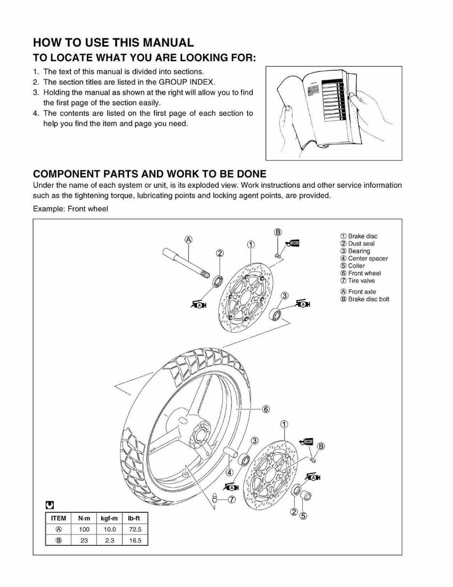
HOW TO USE THIS MANUAL TO LOCATE WHAT YOU ARE LOOKING FOR: 1. The text of this manual is divided into sections. 2. The section titles are listed in the GROUP INDEX. 3. Holding the manual as shown at the right will allow you to find the first page of the section easily. 4. The contents are listed on the first page of each section to help you find the item and page you need. COMPONENT PARTS AND WORK TO BE DONE Under the name of each system or unit, is its exploded view. Work instructions and other service information such as the tightening torque, lubricating points and locking agent points, are provided. Example: Front wheel ITEM N·m kgf-m ® 100 10.0 @ 23 2.3 Ib-ft 72.5 16.5 CD Brake disc (2) Dust seal @ Bearing @ Center spacer @Coller @ Front wheel ({) Tire valve ® Front axle @ Brake disc bolt
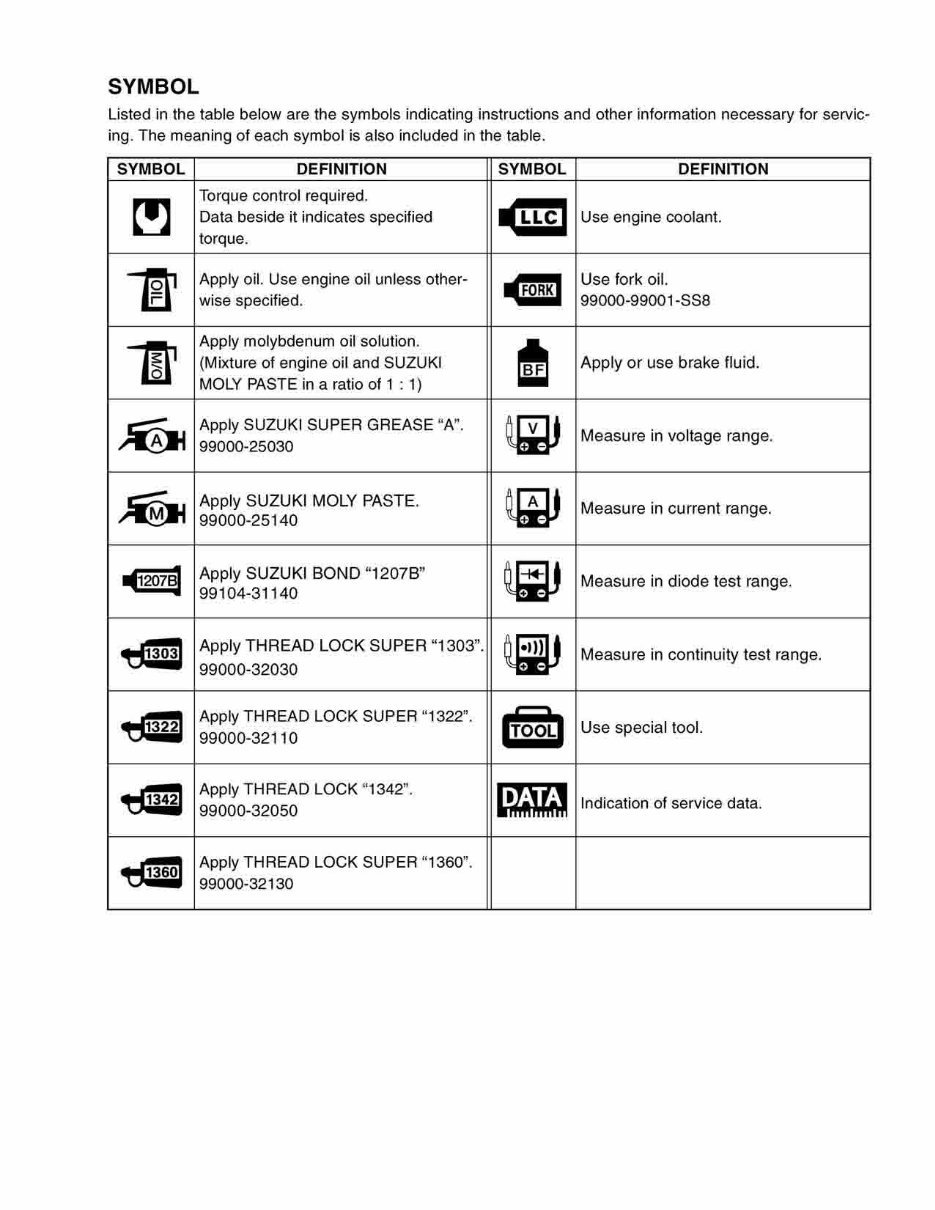
SYMBOL Listed in the table below are the symbols indicating instructions and other information necessary for servic- ing. The meaning of each symbol is also included in the table. SYMBOL DEFINITION SYMBOL DEFINITION ~ Torque control required. -ml Data beside it indicates specified Use engine coolant. torque. l!r Apply oil. Use engine oil unless other- Gil Use fork oil. wise specified. 99000-99001-SS8 m l Apply molybdenum oil solution. I (Mixture of engine oil and SUZUKI Apply or use brake fluid. MOLY PASTE in a ratio of 1 : 1) ~ Apply SUZUKI SUPER GREASE "A". ~ Measure in voltage range. 99000-25030 ~ Apply SUZUKI MOLY PASTE. ~ Measure in current range. 99000-25140 .12078] Apply SUZUKI BOND "1207B" ~ Measure in diode test range. 99104-31140 .. Apply THREAD LOCK SUPER "1303". ij:.~U Measure in continuity test range. 99000-32030 • Apply THREAD LOCK SUPER "1322" . '{ooLl Use special tool. 99000-32110 • Apply THREAD LOCK "1342" . ~~ Indication of service data. 99000-32050 .. Apply THREAD LOCK SUPER "1360" . 99000-32130
ABBREVIATIONS USED IN THIS MANUAL A ABDC AC ACL API ATDC : After Bottom Dead Center : Alternating Current : Air Cleaner, Air Cleaner Box : American Petroleum Institute : After Top Dead Center ATM Pressure: Atmospheric Pressure Atmospheric Pressure Sensor (APS) A/F B BBDC BTDC B+ c : Air Fuel Mixture : Before Bottom Dead Center : Before Top Dead Center : Battery Positive Voltage CKP Sensor : Crankshaft Position Sensor (CKPS) CKT : Circuit CLP Switch : Clutch Lever Position Switch (Clutch Switch) CMP Sensor : Camshaft Position Sensor (CMPS) CO : Carbon Monoxide CPU : Central Processing Unit D DC DMC DOHC DRL : Direct Current : Dealer Mode Coupler : Double Over Head Camshaft : Daytime Running Light E F ECM : Engine Control Module Engine Control Unit (ECU) (FI Control Unit) ECT Sensor : Engine Coolant Temperature Sensor (ECTS), Water Temp. Sensor (WTS) EVAP : Evaporative Emission EVAP Canister: Evaporative Emission Canister (Canister) FI FP FPR FP Relay : Fuel Injection, Fuel Injector : Fuel Pump : Fuel Pressure Regulator : Fuel Pump Relay G GEN GND : Generator : Ground GP Switch : Gear Position Switch H HC : Hydrocarbons lAP Sensor : Intake Air Pressure Sensor (lAPS) IAT Sensor : Intake Air Temperature Sensor (lATS) IG : Ignition L LCD : Liquid Crystal Display LED : Light Emitting Diode (Malfunction Indicator Lamp) LH : Left Hand
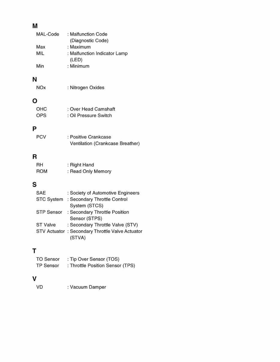
M MAL-Code : Malfunction Code (Diagnostic Code) Max : Maximum MIL : Malfunction Indicator Lamp (LED) Min : Minimum N NOx : Nitrogen Oxides o OHC : Over Head Camshaft OPS : Oil Pressure Switch p PCV : Positive Crankcase Ventilation (Crankcase Breather) R RH : Right Hand ROM : Read Only Memory s T SAE : Society of Automotive Engineers STC System : Secondary Throttle Control System (STCS) STP Sensor : Secondary Throttle Position Sensor (STPS) ST Valve : Secondary Throttle Valve (STV) STV Actuator : Secondary Throttle Valve Actuator (STVA) TO Sensor : Tip Over Sensor (TOS) TP Sensor : Throttle Position Sensor (TPS) V VD : Vacuum Damper
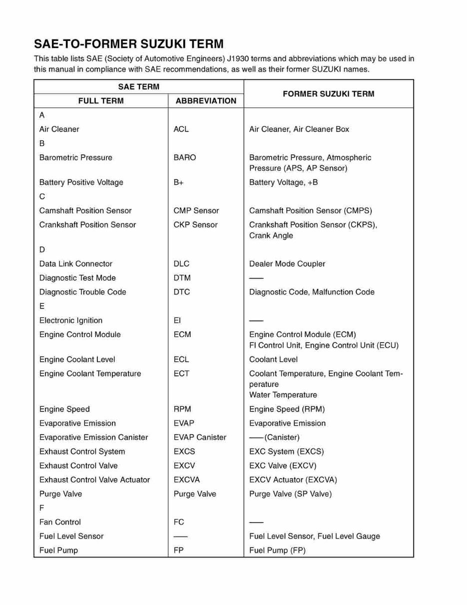
SAE-TO-FORMER SUZUKI TERM This table lists SAE (Society of Automotive Engineers) J1930 terms and abbreviations which may be used in this manual in compliance with SAE recommendations, as well as their former SUZUKI names. SAE TERM FORMER SUZUKI TERM FULL TERM ABBREVIATION A Air Cleaner ACl Air Cleaner, Air Cleaner Box B Barometric Pressure BARO Barometric Pressure, Atmospheric Pressure (APS, AP Sensor) Battery Positive Voltage B+ Battery Voltage, +B C Camshaft Position Sensor CMP Sensor Camshaft Position Sensor (CMPS) Crankshaft Position Sensor CKP Sensor Crankshaft Position Sensor (CKPS), Crank Angle D Data Link Connector DlC Dealer Mode Coupler Diagnostic Test Mode DTM - Diagnostic Trouble Code DTC Diagnostic Code, Malfunction Code E Electronic Ignition EI - Engine Control Module ECM Engine Control Module (ECM) FI Control Unit, Engine Control Unit (ECU) Engine Coolant level ECl Coolant level Engine Coolant Temperature ECT Coolant Temperature, Engine Coolant Tem- perature Water Temperature Engine Speed RPM Engine Speed (RPM) Evaporative Emission EVAP Evaporative Emission Evaporative Emission Canister EVAP Canister -(Canister) Exhaust Control System EXCS EXC System (EXCS) Exhaust Control Valve EXCV EXC Valve (EXCV) Exhaust Control Valve Actuator EXCVA EXCV Actuator (EXCVA) Purge Valve Purge Valve Purge Valve (SP Valve) F Fan Control FC - Fuel level Sensor - Fuel level Sensor, Fuel level Gauge Fuel Pump FP Fuel Pump (FP)
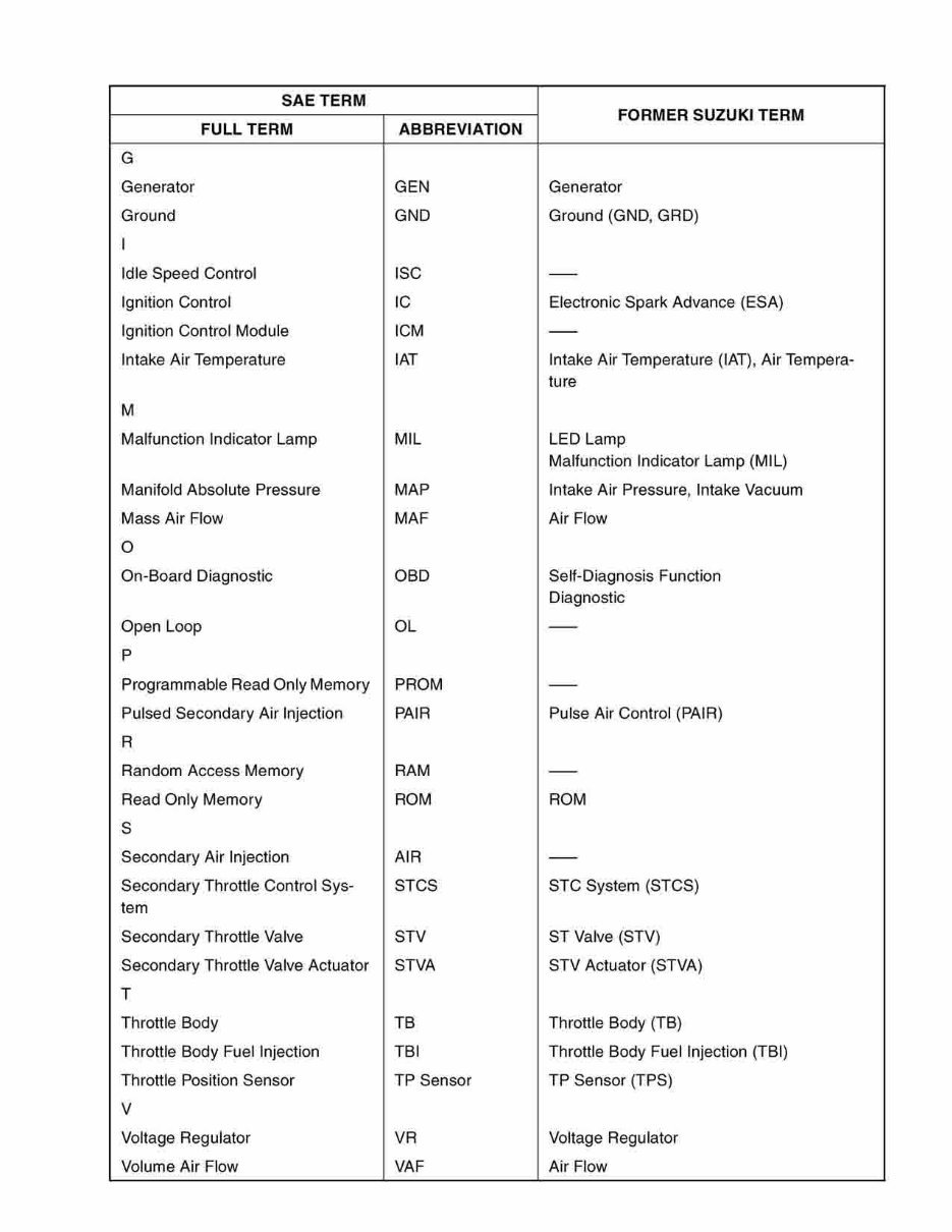
SAE TERM FORMER SUZUKI TERM FULL TERM ABBREVIATION G Generator GEN Generator Ground GND Ground (GND, GRD) I Idle Speed Control ISC - Ignition Control IC Electronic Spark Advance (ESA) Ignition Control Module ICM - Intake Air Temperature IAT Intake Air Temperature (IAT), Air Tempera- ture M Malfunction Indicator Lamp MIL LED Lamp Malfunction Indicator Lamp (MIL) Manifold Absolute Pressure MAP Intake Air Pressure, Intake Vacuum Mass Air Flow MAF Air Flow 0 On-Board Diagnostic OBD Self-Diagnosis Function Diagnostic Open Loop OL - P Programmable Read Only Memory PROM - Pulsed Secondary Air Injection PAIR Pulse Air Control (PAIR) R Random Access Memory RAM - Read Only Memory ROM ROM S Secondary Air Injection AIR - Secondary Throttle Control Sys- STCS STC System (STCS) tem Secondary Throttle Valve STV ST Valve (STV) Secondary Throttle Valve Actuator STVA STV Actuator (STVA) T Throttle Body TB Throttle Body (TB) Throttle Body Fuel Injection TBI Throttle Body Fuel Injection (TBI) Throttle Position Sensor TP Sensor TP Sensor (TPS) V Voltage Regulator VR Voltage Regulator Volume Air Flow VAF Air Flow
This Service & Parts Repair Manual is an essential resource for maintaining and repairing the 2002-2009 Suzuki DL1000 V-Strom. It is a valuable tool for both professional mechanics and DIY enthusiasts, providing high-quality diagrams and detailed instructions for servicing your Suzuki.
The manual covers the following models:
2002 Suzuki DL1000K2 V-Strom
2003 Suzuki DL1000K3 V-Strom
2004 Suzuki DL1000K4 V-Strom
2005 Suzuki DL1000K5 V-Strom
2006 Suzuki DL1000K6 V-Strom
2007 Suzuki DL1000K7 V-Storm
2008 Suzuki DL1000K8 V-Strom
2009 Suzuki DL1000K9 V-Strom
The manual includes comprehensive information on general maintenance, engine, fuel injection system, cooling and lubrication system, electrical system, chassis, servicing, and emission control. It is available in PDF format, compatible with all versions of Windows and Mac, and can be viewed using Adobe Reader. With instant access, this manual is a cost-effective solution that will enhance your understanding of your Suzuki and save you time and money.
Don't miss out on the opportunity to acquire this invaluable resource for maintaining and repairing your Suzuki DL1000 V-Strom. Get your copy now and take control of your vehicle's maintenance and repair needs.
Recently Viewed
5,521,897Happy Clients
2,594,462eManuals
1,120,453Trusted Sellers
15Years in Business
Price:
Actual Price:
2002-2009 Suzuki DL1000 V-Strom Workshop Service & Parts Repair Manual 2002 2003 2004 2005 2006 2007 2008 2009