QUICK REFERENCE DATA TIRE INFLATION PRESSURE (COLD)* Load P si Tire Pressure Front Rear kPa psi kPa "Solo riding 28 Dual riding 32 200 225 32 36 225 250 » Tire inflation pressure for factory equipped tires. Aftermarket tires may require different inflation pressure. RECOMMENDED LUBRICANTS AND FLUIDS Fuel Regular unleaded U.S. and Canada 87 [( R + M) /2 method] or 91 octane or hi gher U.K. and all other s 85-95 octane Engine oii SAE 10W-40 API grade SE or SF Capacity Change 2.4 L (2-5 U.S. qtJ2,1 Imp. qt.) "• Change and filter 2.8 L (3.0 U.S. qt J2.5 Imp. qt. ) j> ""At overhaul 3.3 L(3.5 U.S. qt/2.9 Imp. qt.) C$dlanf Ethylene glycol * Capacity at change 1.7 L ( 1.8 U.S. qtJ1.5 imp. qt. ) ^tt»al drive oil SAi 90 hypoid gear oil with «. GL-5 under API classification I ~ Capacity at change 2-2.2 m) (6.8-7.0 U.S. qt J7.4-7.7 Imp. qt.) ' • f rake fluid DOT 4 'ulch hydraulic fluid DOT 3 or DOT 4 -Hmtterf refilling Distilled water 5hptnt fork oil capacity (each fork leg) SAE 10W 3 "i 981 ,^- Right-hand fork 388 ml 12.1 oz. ; Left -hand forte 370 ml 12.5 oz. ;,:if8<M981 ;.: u,s. 383 mi 13.4 oz. r '"" U.K. 394 ml 13.8 oz. *, /It92-1993 386 ml 13.5 oz. 'f: W§4-on 412ml 14.502, J*Brflr*l fork oil leyet dimension "' t 1985-1989 153 mm 6.02 in. t990-1991 UJS. and U.K. 175 mm 6.89 in. • Canada 187mm 7.36 in. 199 2 -199 3 y U.S., Canada and U.K. 178 mm 7.01 in. ' 1994-on 177mm 6.97 in. J^ »rk oH t ype SAE 10W fork oil Cables and pivot points Cabie lube or SAE 10W/30 motor oil f; MAINTENANCE AND TUNE UP TIGHTENING TORQUES Item N.m ft.-lb. ^•Oil drain plug 18-23 13-16.5 / \telve adjuster locknut 13-16 9.5-11.5 Cylinder head side cover bolts (side opposite spark plug) 21-23 15-18
INTRODUCTION This detailed, comprehensive manual covers the U.S and U.K. models of the Suzuki Intruder 700-800 cc V- twins from 1985-on. The expert text gives complete information on mainte- nance, tune-up, repair and overhaul. Hundreds of photos and drawings guide you through every step. The book includes all you will need to know to keep your Suzuki running right. Throughout this book where differences occur among the models, they are clearly identified. A shop manual is a reference. You want to be able to find information fast. As in all Clymer books, this one is designed with you in mind. All chapters are thumb tabbed. Important items are extensively indexed at the rear of the book. All procedures, tables, photos, etc., in this manual are for the reader who may be working on the bike for the first time or using this manual for the first time. All the most frequently used specifications and capacities are summarized in the Quick Reference Data pages at the front of the book. Keep the book handy in your tool box. It will help you better understand how your bike runs, lower repair costs and generally improve your satisfaction with the bike.
CHAPTER ONE GENERAL INFORMATION This detailed, comprehensive manual covers the U.S. and the U.K. models of the Suzuki Intruder 700-800 cc V-twins from 1985-on. Table 1 lists the chassis numbers (VIN) for models covered in this manual. Troubleshooting, tune-up, maintenance and repair are not difficult, if you know what tools and equip- ment to use and what to do. Step-by-step instructions guide you through jobs ranging from simple main- tenance to complete engine and suspension over- haul. This manual can be used by anyone from a first time do-it-yourselfer to a professional mechanic. Detailed drawings and clear photographs give you all the information you need to do the work right. Some procedures will require the use of special tools. The resourceful mechanic can, in many cases, think of acceptable substitutes for special tools, there is always another way. This can be as simple as using a few pieces of threaded rod, washers and nuts to remove or install a bearing or fabricating a tool from scrap material. However, using a substitute for a special tool is not recommended as it can be danger- ous to and may damage the part. If you find that a tool can be designed and safely made, but will require some type of machine work, you may want to search out a local community college or high school that has a machine shop curriculum. Some shop teachers welcome outside work that can be used as practical shop applications for advanced students. Table 1 lists model coverage with VIN and frame serial numbers. Metric and U.S. standards are used throughout this manual and U.S. to metric conver- sion is given in Table 2. Tables 1-5 are located at the end of this chapter. MANUAL ORGANIZATION This chapter provides general information and discusses equipment and tools useful both for pre- ventive maintenance and troubleshooting.
Chapter Two provides methods and suggestions for quick and accurate diagnosis and repair of prob- lems. Troubleshooting procedures discuss typical symptoms and logical methods to pinpoint the trouble. Chapter Three explains all periodic lubrication and routine maintenance necessary to keep your Suzuki operating well and competitive. Chapter Three also includes recommended tune-up proce- dures, eliminating the need to constantly consult other chapters on the various assemblies. Subsequent chapters describe specific systems such as the engine top end, engine bottom end, clutch, transmission, fuel, exhaust, electrical, cool- ing, suspension, drive train, steering and brakes. Each chapter provides disassembly, repair and as- sembly procedures in simple step-by-step form. If a repair is impractical for a home mechanic, it is so indicated. It is usually faster and less expensive to take such repairs to a Suzuki dealer or competent repair shop. Specifications concerning a particular system are included at the end of the appropriate chapter. NOTES, CAUTIONS AND WARNINGS The terms NOTE, CAUTION and WARNING have specific meanings in this manual. A NOTE provides additional information to make a step or procedure easier or clearer. Disregarding a NOTE could cause inconvenience, but would not cause damage or personal injury. A CAUTION emphasizes an area where equip- ment damage could occur. Disregarding a CAU- TION could cause permanent mechanical damage; however, personal injury is unlikely. A WARNING emphasizes an area where personal injury or even death could result from negligence. Mechanical damage may also occur. WARNINGS are to be taken seriously. In some cases, serious injury and death has resulted from disregarding similar warnings. SAFETY FIRST Professional mechanics can work for years and never sustain a serious injury. If you observe a few rules of common sense and safety, you can enjoy many safe hours servicing your own machine. If you ignore these rules you can hurt yourself or damage the equipment. 1. Never use gasoline as a cleaning solvent. 2. Never smoke or use a torch in the vicinity of flammable liquids, such as cleaning solvent, in open containers. 3. If welding or brazing is required on the machine, remove the fuel tank and rear shock to a safe dis tance, at least 50 feet away. 4. Use the proper sized wrenches to avoid damage to fasteners and injury to yourself. 5. When loosening a tight or stuck nut, be guided by what would happen if the wrench should slip. Be careful; protect yourself accordingly. 6. When replacing a fastener, make sure to use one with the same measurements and strength as the old one. Incorrect or mismatched fasteners can result in
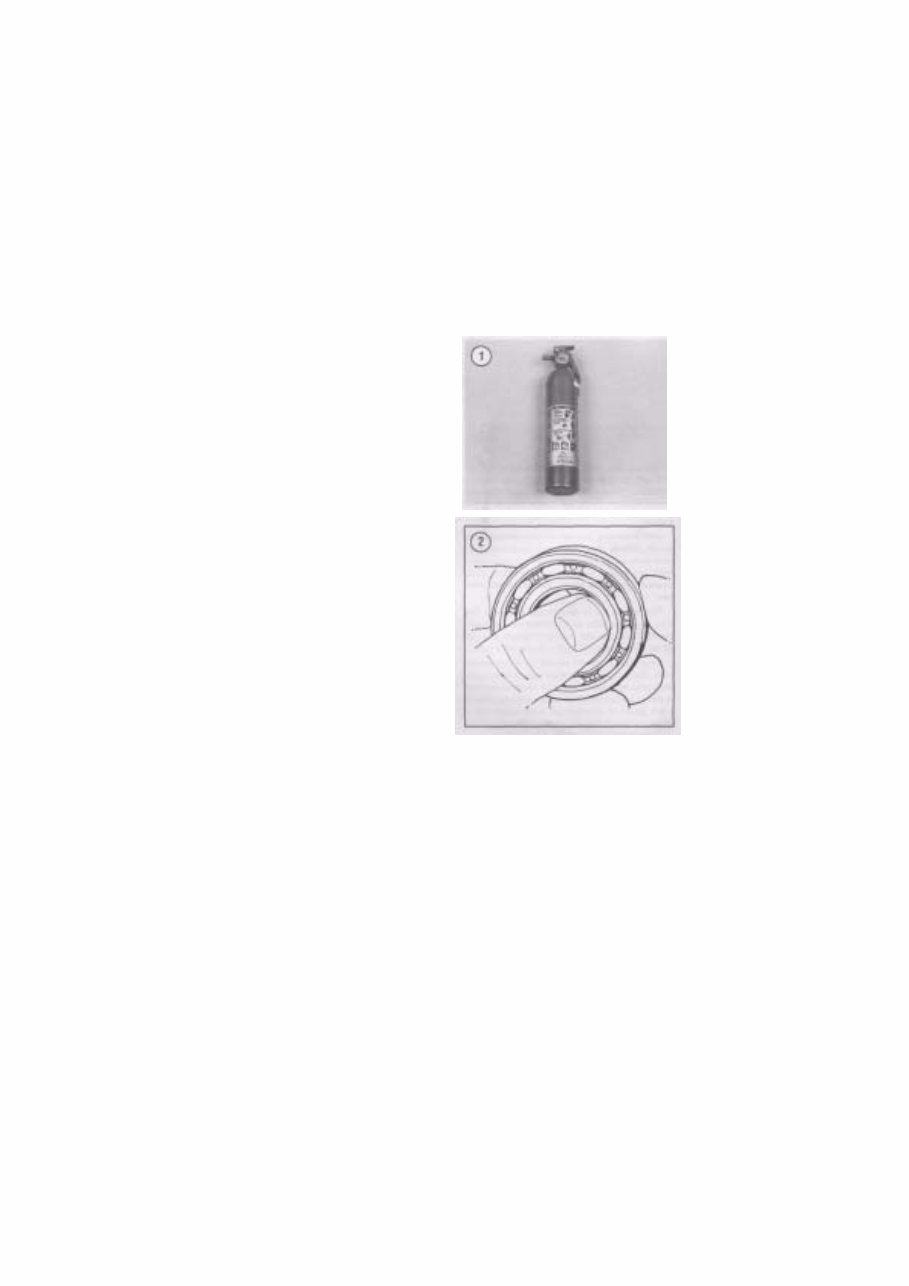
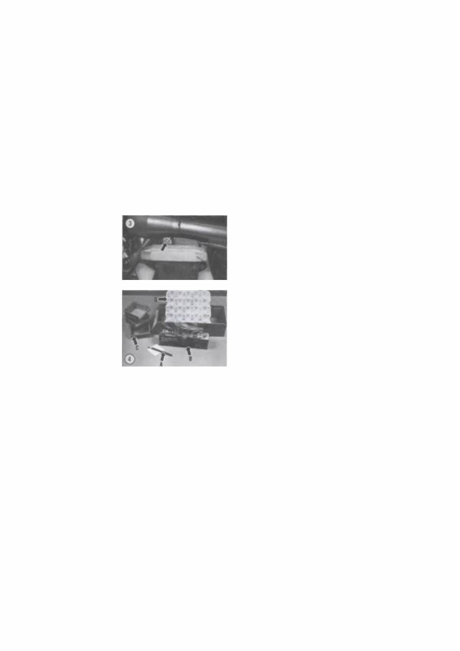
damage to the bike and possible personal injury. Beware of fastener kits that are filled with cheap and poorly made nuts, bolts, washers and cotter pins. Refer to Fasteners in this chapter for additional information. 7. Keep all hand and power tools in good condition. Wipe greasy and oily tools after using them. They are difficult to hold and can cause injury. Replace or repair worn or damaged tools. 8. Keep your work area clean and uncluttered. 9. Wear safety goggles during all operations involv ing drilling, grinding, the use of a cold chisel or anytime you feel unsure about the safety of your eyes. Safety goggles should also be worn anytime solvent and compressed air is used to clean a part. 10. Keep an approved fire extinguisher nearby (Fig ure 1). Be sure it is rated for gasoline (Class B) and electrical (Class C) fires. 11. When drying bearings or other rotating pans with compressed air, never allow the air jet to rotate the bearing or part. The air jet is capable of rotating them at speeds far in excess of those for which they were designed. The bearing or rotating part is very likely to disintegrate and cause serious injury and damage. To prevent bearing damage when using compressed air, hold the inner bearing race by hand (Figure 2). SERVICE HINTS Most of the service procedures covered are straightforward and can be performed by anyone reasonably handy with tools. It is suggested, how- ever, that you consider your own capabilities care- fully before attempting any operation involving major disassembly of the engine or transmission. Take your time and do the job right. Do not forget that a newly rebuilt engine must be broken-in the same way as a new one. Keep the rpm within the limits given in your owner's manual when you get back on the road or out in the dirt. 1. "Front," as used in this manual, refers to the front of the bike; the front of any component is the end closest to the front of the bike. The "left-" and "right- hand" sides refer to the position of the parts as viewed by a rider sitting on the seat facing forward. For exam ple, the throttle control is on the right-hand side. These rules are simple, but confusion can cause a major inconvenience during service. 2. Whenever servicing the engine or clutch, or when removing a suspension component, the bike should be secured in a safe manner. WARNING Never disconnect the positive (+) bat- tery cable unless the negative (-) cable has first been disconnected. Discon- necting the positive cable while the negative cable is still connected may cause a spark. This could ignite hydro- gen gas given off by the battery, causing an explosion. 3. Disconnect the negative battery cable (Figure 3) when working on or near the electrical, clutch, or starter systems and before disconnecting any elec trical wires. On most batteries, the negative terminal will be marked with a minus (-) sign and the positive terminal with a plus (+) sign. 4. Tag all similar internal parts for location and mark all mating parts for position (A, Figure 4). Record number and thickness of any shims as they are removed. Small parts such as bolts can be iden tified by placing them in plastic sandwich bags (B, Figure 4). Seal and label them with masking tape.
5. Place parts from a specific are of the engine (e.g. cylinder head, cylinder, clutch, shift mechanism, etc.) into plastic boxes (C, Figure 4) to keep them separated. 6. When disassembling transmission shaft assem blies, use an egg flat (the type that restaurants get their eggs in) (D, Figure 4) and set the parts from the shaft in one of the depressions in the same order in which is was removed. NOTE Some of the procedures or service speci- fications listed in this manual may not be applicable if your Suzuki has been modified or if it has been equipped with non-stock equipment. When modifying or installing non-stock equipment, file all printed instruction or technical in- formation regarding the new equipment in a folder or notebook for future refer- ence. If your Suzuki was purchased sec- ond hand, the previous owner may have installed non-stock parts. If necessary, consult with your dealer or the acces- sory manufacturer on components that may affect tuning or repair procedures. 1. Wiring should be tagged with masking tape and marked as each wire is removed. Again, do not rely on memory alone. 8. Finished surfaces should be protected from physical damage or corrosion. Keep gasoline and brake fluid off painted surfaces. 9. Use penetrating oil on frozen or tight bolts, then strike the bolt head a few times with a hammer and punch (use a screwdriver on screws). Avoid the use of heat where possible, as it can warp, melt or affect the temper of parts. Heat also ruins finishes, espe cially paint and plastics. 10. No parts removed or installed (other than bush ings and bearings) in the procedures given in this manual should require unusual force during disas sembly or assembly. If a part is difficult to remove or install, find out why before proceeding. 11. Cover all openings after removing parts or com ponents to prevent dirt, small tools, etc. from falling in. 12. Read each procedure completely while looking at the actual parts before starting a job. Make sure you thoroughly understand what is to be done and then carefully follow the procedure, step-by-step. 13. Recommendations are occasionally made to re fer service or maintenance to a Suzuki dealer or a specialist in a particular field. In these cases, the work will be done more quickly and economically than if you performed the job yourself. 14. In procedural steps, the term "replace" means to discard a defective part and replace it with a new or exchange unit. "Overhaul" means to remove, disas semble, inspect, measure, repair or replace defective parts, reassemble and install major systems or parts. 15. Some operations require the use of a hydraulic press. Unless you have a press, it would be wiser to have these operations performed by a shop equipped for such work, rather than to try to do the job yourself with makeshift equipment that may damage your machine. 16. Repairs go much faster and easier if your ma chine is clean before you begin work. There are many special cleaners on the market, like Simple Green or Bel-Ray Degreaser, for washing the engine and related parts. Follow the manufacturer's direc tions on the container for the best results. Clean all oily or greasy parts with cleaning solvent as you remove them. WARNING Never use gasoline as a cleaning agent. It presents an extreme fire hazard. Be sure to work in a well-ventilated area when using cleaning solvent. Keep afire extinguisher, rated for gasoline fires, handy in any case. CAUTION If you use a car wash to clean your bike, don't direct the high pressure water hose at steering bearings, carburetor hoses,
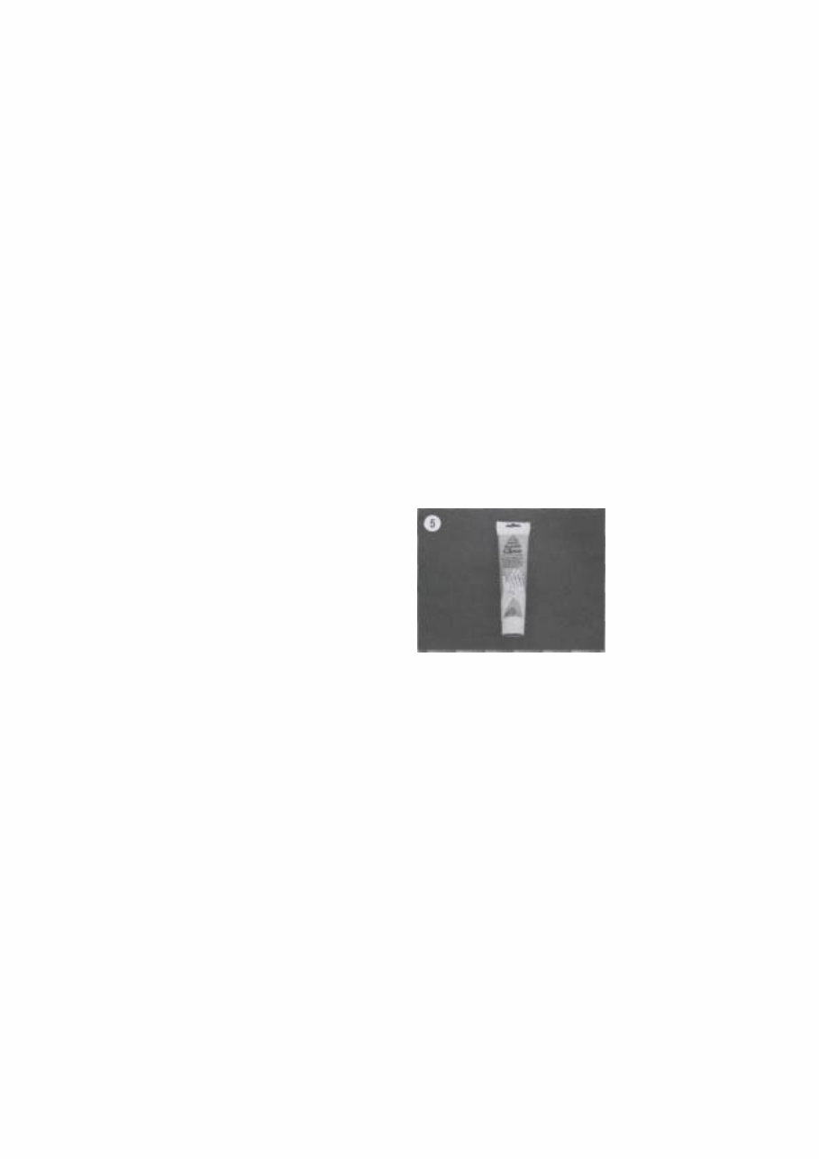
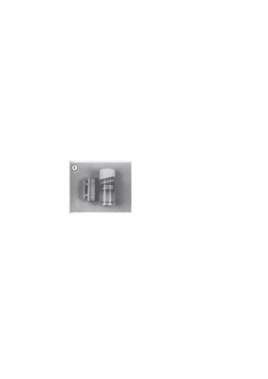
suspension linkage components, wheel bearings and electrical components. The water will flush grease out of the bearings or damage the seals. 17. Much of the labor charges for repairs made by dealers are for the time involved during in the re moval, disassembly, assembly, and reinstallation of other parts in order to reach the defective part. It is frequently possible to perform the preliminary op erations yourself and then take the defective unit to the dealer for repair at considerable savings. 18. If special tools are required, make arrangements to get them before you start. It is frustrating and time-consuming to get partly into a job and then be unable to complete it. 19. Make diagrams (or take a Polaroid picture) wherever similar-appearing parts are found. For in stance, crankcase bolts are often not the same length. You may think you can remember where everything came from—but mistakes are costly. There is also the possibility that you may be sidetracked and not return to work for days or even weeks—in which the time carefully laid out parts may have become dis turbed. 20. When assembling parts, be sure all shims and washers are replaced exactly as they came out. 21. Whenever a rotating part butts against a station ary part, look for a shim or washer. Use new gaskets if there is any doubt about the condition of the old ones. A thin coat of oil on non-pressure type gaskets may help them seal more effectively. 22. High spots may be sanded off a piston with sandpaper, but fine emery cloth and oil will do a much more professional job. 23. Carbon can be removed from the head, the piston crowns and the exhaust ports with a dull screwdriver. Do not scratch machined surfaces. Wipe off the surface with a clean cloth when fin ished. 24. A baby bottle makes a good measuring device for adding oil to the front forks. Get one that is graduated in fluid ounces and cubic centimeters. After it has been used for this purpose, do not let a small child drink out of it as there will always be an oil residue in it. 25. If it is necessary to make a clutch cover or ignition cover gasket and you do not have a suitable old gasket to use as a guide, you can use the outline of the cover and gasket material to make a new gasket. Apply engine oil to the cover gasket surface. Then place the cover on the new gasket material and apply pressure with your hands. The oil will leave a very accurate outline on the gasket material that can be cut around. CAUTION When purchasing gasket material to make a gasket, measure the thickness of the old gasket and purchase gasket material with the same approximate thickness. 26. Heavy grease can be used to hold small parts in place if they tend to fall out during assembly. How ever, keep grease and oil away from electrical and brake components. 27. The carburetor is best cleaned by disassembling it and soaking the parts in a commercial cleaning solvent. Never soak gaskets and rubber parts in these cleaners. Never use wire to clean out jets and air passages. They are easily damaged. Use compressed air to blow out the carburetor only if the float has been removed first. 28. There are many items available that can be used on your hands before and after working on your bike. A little preparation prior to getting "all greased up" will help when cleaning up later. Before starting out, work Vaseline, soap or a product such as Invisible Glove (Figure 5) onto your forearms, into your hands and under your fingernails and cuticles. This will make cleanup a lot easier. For cleanup, use a waterless hand soap such as Sta-Lube and then finish up with powdered Boraxo and a fingernail brush (Figure 6).
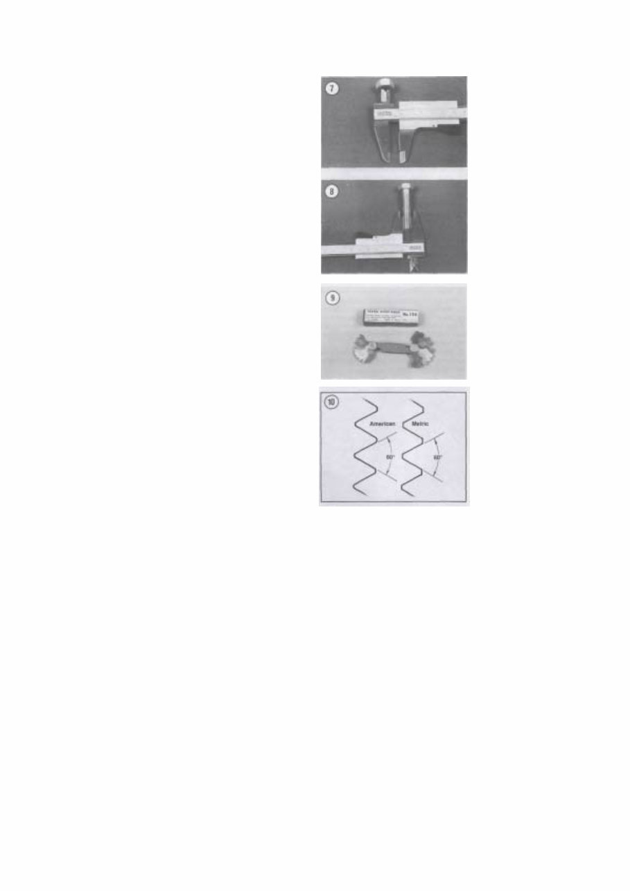
PARTS REPLACEMENT When you order parts from the dealer or other parts distributor, always order by frame and engine serial numbers. Refer to Table 1. Compare new parts to old before purchasing them. If they are not alike, have the parts manager explain the difference to you. TORQUE SPECIFICATIONS Torque specifications throughout this manual are given in Newton-meters (N.m) and foot-pounds (ft.- lb.). Existing torque wrenches calibrated in meter kilo- grams can be used by performing a simple conver- sion. All you have to do is move the decimal point one place to the right; for example, 3.5 mkg = 35 N.m. This conversion is accurate enough for me- chanical work even though the exact mathematical conversion is 3.5 mkg = 34.3 N-m. Refer to Table 3 for general torque specifications for various size screws, bolts and nuts that may not be listed in the respective chapters. To use the table, first determine the size of the bolt or nut. Use a vernier caliper and measure the inside dimension of the threads of the nut (Figure 7) and across the threads for a bolt (Figure 8). FASTENERS The materials and designs of the various fasteners used on your Suzuki are not arrived at by chance or accident. Fastener design determines the type of tool required to work the fastener. Fastener material is carefully selected to decrease the possibility of physical failure. Nuts, bolts and screws are manufactured in a wide range of thread patterns. To join a nut and bolt, the diameter of the bolt and the diameter of the hole in the nut must be the same. It is just as important that the threads on both be properly matched. The best way to tell if the threads on 2 fasteners are matched is to turn the nut on the bolt (or the bolt into the threaded hole in a piece of equipment) with fingers only. Be sure both pieces are clean. If much force is required, check the thread condition on each fastener. If the thread condition is good but the fasteners jam, the threads are not compatible. A thread pitch gauge (Figure 9) can also be used to determine pitch. Suzuki motorcycles are manufac-
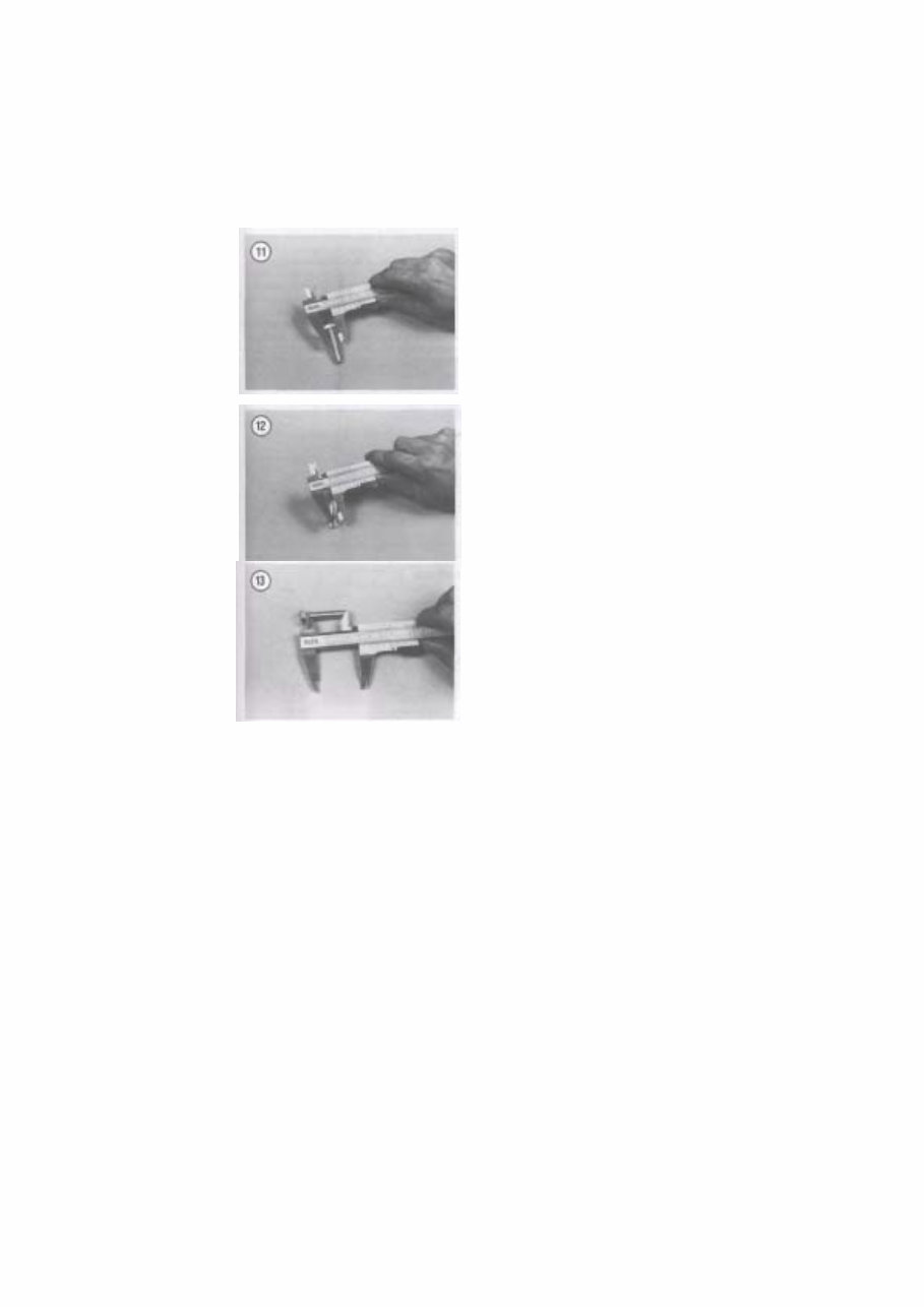
tured with ISO (International Organization for Standardization) metric fasteners. The threads are cut differently than that of American fasteners (Fig- ure 10). Most threads are cut so that the fastener must be turned clockwise to tighten it. These are called right- hand threads. Some fasteners have left-hand threads; they must be turned counterclockwise to be light- ened. Left-hand threads are used in locations where normal rotation of the equipment would tend to loosen a right-hand threaded fastener. ISO Metric Screw Threads ISO (International Organization for Stand- ardization) metric threads come in 3 standard thread sizes: coarse, fine and constant pitch. The ISO coarse pitch is used for most all common fastener applica- tions. The fine pitch thread is used on certain preci- sion tools and instruments. The constant pitch thread is used mainly on machine pans and not for fasten- ers. The constant pitch thread, however, is used on all metric thread spark plugs. ISO metric threads are specified by the capital letter M followed by the diameter in millimeters and the pitch (or the distance between each thread) in millimeters separated by the sign x. For example a M8 x 1.25 bolt is one that has a diameter of 8 millimeters with a distance of 1.25 millimeters be- tween each thread. The measurement across 2 flats on the head of the bolt (Figure 11) indicates the proper wrench size to be used. Figure 12 shows how to determine bolt diameter. NOTE When purchasing a bolt from a dealer or parts store, it is important to know how to specify bolt length. The correct way to measure bolt length is by meas- uring the length starting from under- neath the bolt head to the end of the bolt (Figure 13). Always measure bolt length in this manner to avoid purchas- ing bolts that are too long or too short. Machine Screws There are many different types of machine screws. Figure 14 shows a number of screw heads requiring different types of turning tools. Heads are also de- signed to protrude above the metal (round) or to be slightly recessed in the metal (flat). See Figure 15. Bolts Commonly called bolts, the technical name for these fasteners is cap screws. Metric bolts are de- scribed by the diameter and pitch (or the distance
This is the complete official full factory service repair manual for the Suzuki Intruder VS700 VS800 1995. It provides detailed information for gearbox & clutch, electric starter, crankshaft/transmission/balancer, wheels & tires, electrical system, braking system, suspension, periodic checks & adjustments, wiring diagrams, engine lubrication and cooling, ignition system, transmission system, troubleshooting, lubrication system, rear wheel system, cylinder head/valves, cooling system, engine removal and installation, general information, battery/charging system, chassis, technical information & specifications, lights/meters/switches, frame/body panels/exhaust system, maintenance, alternator/starter clutch, fenders and exhaust pipe, front wheel and steering system, specifications, engine fuel system, crankcase/piston/cylinder, engine combustion system, fuel injection system, body & fixtures. This service manual is your number one source for repair and service information. It is specifically written for the do-it-yourselfer as well as the experienced mechanic. The manual provides step-by-step instructions based on the complete disassembly of the machine. It includes detailed substeps that expand on repair procedure information, notes, cautions, and warnings throughout each chapter, numbered instructions, bold figure numbers, detailed illustrations, drawings, photos, and an enlarged inset to help you identify and examine parts in detail. The numbered table of contents makes it easy to find the information you need fast. Additionally, it makes it easy to diagnose and repair problems with your machine's electrical system. Troubleshooting and electrical service procedures are combined with detailed wiring diagrams for ease of use. The manual comes in PDF format, which can work under all PC-based Windows operating systems and Mac as well. It saves to your hard drive and can be burned to CD-ROM. All pages are printable. No need to pay for shipping and wait for the overpriced paper textbook or CD-ROM to arrive via snail mail. Get your Suzuki Intruder VS700 VS800 1995 service manual now!
File Format: PDF
Language: English
Printable: without any restriction
Delivery: link will appear on the checkout page after payment is complete
Requirements: Adobe Reader
Recently Viewed
5,521,897Happy Clients
2,594,462eManuals
1,120,453Trusted Sellers
15Years in Business
Price:
Actual Price:
1995 Suzuki Intruder VS700 VS800 Service & Repair Manual