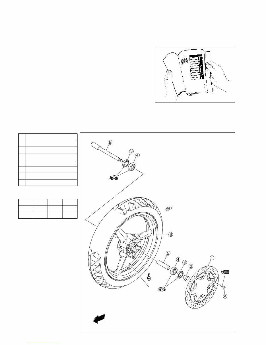
HOW TO USE THIS MANUAL TO LOCATE WHAT YOU ARE LOOKING FOR: 1. The text of this manual is divided into sections. 2. The section titles are listed in the GROUP INDEX. 3. Holding the manual as shown at the right will allow you to find the first page of the section easily. 4. The contents are listed on the first page of each section to help you find the item and page you need. COMPONENT PARTS AND WORK TO BE DONE Under the name of each system or unit, is its exploded view. Work instructions and other service information such as the tightening torque, lubricating points and locking agent points, are provided. Example: Front wheel 1 Brake disc 2 Collar 3 Dust seal 4 Bearing 5 Spacer 6 Front wheel A Front axle B Brake disc bolt ITEM N·m kgf-m lbf-ft A 18 1.8 13.0 B 65 6.5 47.0 FWD Downloaded from www.Manualslib.com manuals search engine
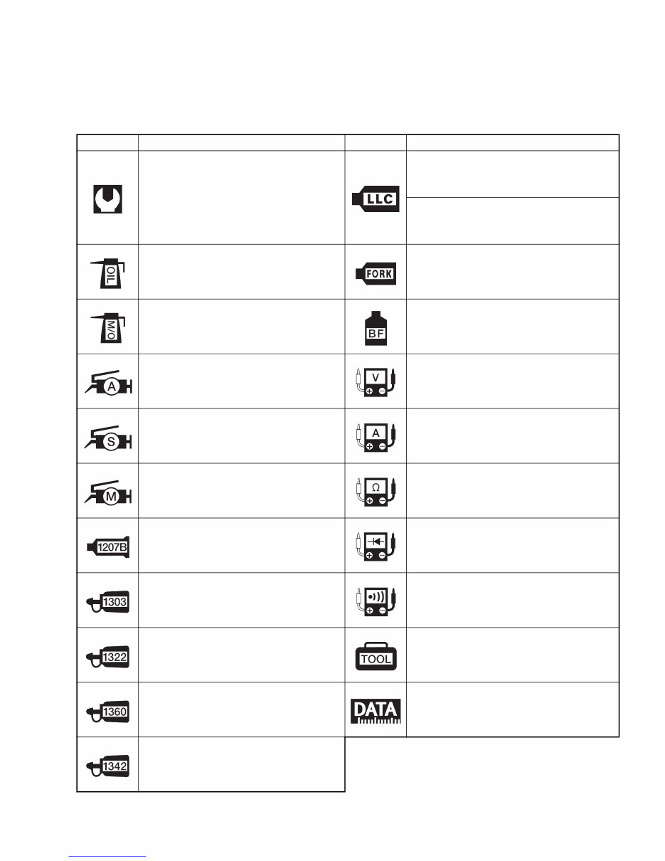
SYMBOL MARKS AND MATERIALS Listed in the table below are the symbols indicating instructions and other information. The meaning of each symbol is also included in the table. SYMBOL DEFINITION SYMBOL DEFINITION Torque control required. Data beside it indicates specified torque. Use SUZUKI SUPER LONG LIFE COOLANT (BLUE). 99000-99032-20X Use SUZUKI LONG LIFE COOLANT (GREEN) or equivalent. 99000-99032-12X Apply oil. Use engine oil or transmis- sion oil unless otherwise specified. Use SUZUKI FORK OIL G10 or equivalent. 99000-99001-G10 Apply molybdenum oil solution. (Mixture of engine oil and SUZUKI MOLY PASTE in a ratio of 1:1) Apply or use brake fluid. Apply SUZUKI SUPER GREASE “A” or equivalent. 99000-25010 Measure in voltage range. Apply SUZUKI SILICONE GREASE or equivalent. 99000-25100 Measure in current range. Apply SUZUKI MOLY PASTE or equivalent. 99000-25140 Measure in resistance range. Apply SUZUKI BOND “1207B” or equivalent. 99000-31140 Measure in diode test range. Apply THREAD LOCK CEMENT SUPER “1303” or equivalent. 99000-32030 Measure in continuity test range. Apply THREAD LOCK CEMENT SUPER “1322” or equivalent. 99000-32110 Use special tool. Apply THREAD LOCK CEMENT SUPER “1360” or equivalent. 99000-32130 Indication of service data. Apply THREAD LOCK CEMENT SUPER“1342” or equivalent. 99000-32050 Downloaded from www.Manualslib.com manuals search engine
ABBREVIATIONS USED IN THIS MANUAL A ABDC : After Bottom Dead Center AC : Alternating Current ACL : Air Cleaner, Air Cleaner Box API : American Petroleum Institute ATDC : After Top Dead Center A/F : Air Fuel Mixture B BBDC : Before Bottom Dead Center BTDC : Before Top Dead Center B+ : Battery Positive Voltage C CKP Sensor : Crankshaft Position Sensor (CKPS) CKT : Circuit CLP Switch : Clutch Lever Position Switch (Clutch Switch) CO : Carbon Monoxide CPU : Central Processing Unit D DC : Direct Current DRL : Daytime Running Light DTC : Diagnostic Trouble Code E ECM : Engine Control Module Engine Control Unit (ECU) (FI Control Unit) ECT Sensor : Engine Coolant Temperature Sensor (ECTS), Water Temp. Sensor (WTS) F FI : Fuel Injection, Fuel Injector FP : Fuel Pump FPR : Fuel Pressure Regulator FP Relay : Fuel Pump Relay FWD : Forward G GEN : Generator GND : Ground GP Switch : Gear Position Switch H HC : Hydrocarbons HO2 Sensor : Heated Oxygen Sensor (HO2S) I IAP Sensor : Intake Air Pressure Sensor (IAPS) (MAP Sensor) IAT Sensor : Intake Air Temperature Sensor (IATS) IG : Ignition ISC Valve : Idle Speed Control Valve (ISCV) J JASO : Japanese Automobile Standards Organization L LCD : Liquid Crystal Display LED : Light Emitting Diode (Malfunction Indicator Lamp) LH : Left Hand M MAL-Code : Malfunction Code (Diagnostic Code) Max : Maximum MIL : Malfunction Indicator Lamp (LED) Min : Minimum N NOX : Nitrogen Oxides O OHC : Over Head Camshaft OPS : Oil Pressure Switch Downloaded from www.Manualslib.com manuals search engine
P PAIR : Pulsed Secondary Air Injection PCM : Power control module PCV : Positive Crankcase Ventilation (Crankcase Breather) R RH : Right Hand ROM : Read Only Memory S SAE : Society of Automotive Engineers SDS : Suzuki Diagnosis System T TO Sensor : Tip-Over Sensor (TOS) TP Sensor : Throttle Position Sensor (TPS) WIRE COLOR B : Black Gr : Gray R : Red Bl : Blue Lbl : Light blue V : Violet Br : Brown Lg : Light green W : White Dg : Dark green O : Orange Y : Yellow G : Green P : Pink B/Bl : Black with Blue tracer O/BI : Orange with Blue tracer B/Br : Black with Brown tracer O/R : Orange with Red tracer B/G : Black with Green tracer O/W : Orange with White tracer B/R : Black with Red tracer O/Y : Orange with Yellow tracer B/W : Black with White tracer R/B : Red with Black tracer B/Y : Black with Yellow tracer R/Y : Red with Yellow tracer Bl/G : Blue with Green tracer W/B : White with Black tracer Bl/W : Blue with White tracer W/R : White with Red tracer Bl/Y : Blue with Yellow tracer Y/G : Yellow with Green tracer Br/Y : Brown with Yellow tracer Y/R : Yellow with Red tracer G/Y : Green with Yellow tracer Y/W : Yellow with White tracer O/B : Orange with Black tracer Downloaded from www.Manualslib.com manuals search engine
GENERAL INFORMATION 1-1 1 GENERAL INFORMATION CONTENTS WARNING/CAUTION/NOTICE/NOTE ......................................................... 1- 2 GENERAL PRECAUTIONS ......................................................................... 1- 2 SUZUKI GW250L3 (’13-MODEL) ................................................................ 1- 4 SERIAL NUMBER LOCATION .................................................................... 1- 4 FUEL, OIL AND ENGINE COOLANT RECOMMENDATION ...................... 1- 5 FUEL ...................................................................................................... 1- 5 ENGINE OIL .......................................................................................... 1- 5 BRAKE FLUID ....................................................................................... 1- 6 FRONT FORK OIL................................................................................. 1- 6 ENGINE COOLANT RECOMMENDATION .......................................... 1- 6 BREAK-IN PROCEDURES .......................................................................... 1- 7 CYLINDER IDENTIFICATION...................................................................... 1- 7 INFORMATION LABELS ............................................................................. 1- 8 SPECIFICATIONS........................................................................................ 1- 9 DIMENSIONS AND CURB MASS ......................................................... 1- 9 ENGINE ................................................................................................. 1- 9 DRIVE TRAIN ........................................................................................ 1- 9 CHASSIS ............................................................................................... 1-10 ELECTRICAL ........................................................................................ 1-10 CAPACITIES ......................................................................................... 1-10 COUNTRY AND AREA CODES The following codes stand for the applicable country(-ies) and area(-s). CODE COUNTRY or AREA EFFECTIVE FRAME NO. P-12 Indonesia LC6GJ55B0C1 100001 – P-21 E.U. LC6DC111101 100001 – P-24 Australia LC6DC111201 100001 – P-71 Mexico LC6GJ55E D1 100001 – Downloaded from www.Manualslib.com manuals search engine
1-2 GENERAL INFORMATION WARNING/CAUTION/NOTICE/NOTE Please read this manual and follow its instructions carefully. To emphasize special information, the symbol and the words WARNING, CAUTION, NOTICE and NOTE have special meanings. Pay special attention to the messages highlighted by these signal words. Indicates a potential hazard that could result in death or injury. Indicates a potential hazard that could result in motorcycle damage. Indicates a potential hazard that could result in motorcycle or equipment damage. NOTE: Indicates special information to make maintenance easier or instructions clearer. Please note, however, that the warnings and cautions contained in this manual cannot possibly cover all potential hazards relating to the servicing, or lack of servicing, of the motorcycle. In addition to the WARN- INGS, CAUTIONS and NOTICES stated, you must use good judgement and basic mechanical safety princi- ples. If you are unsure about how to perform a particular service operation, ask a more experienced mechanic for advice. GENERAL PRECAUTIONS * Proper service and repair procedures are important for the safety of the service mechanic and the safety and reliability of the motorcycle. * When 2 or more persons work together, pay attention to the safety of each other. * When it is necessary to run the engine indoors, make sure that exhaust gas is forced out- doors. * When working with toxic or flammable materials, make sure that the area you work in is well- ventilated and that you follow all of the material manufacturer’s instructions. * To avoid getting burned, do not touch the engine, engine oil, radiator and exhaust system until they have cooled. Downloaded from www.Manualslib.com manuals search engine
GENERAL INFORMATION 1-3 * Never use gasoline as a cleaning solvent. * After servicing the fuel, oil, water, exhaust or brake systems, check all lines and fittings related to the system for leaks. * If parts replacement is necessary, replace the parts with Suzuki Genuine Parts or their equiva- lent. * When removing parts that are to be reused, keep them arranged in an orderly manner so that they may be reinstalled in the proper order and orientation. * Be sure to use special tools when instructed. * Make sure that all parts used in reassembly are clean. Lubricate them when specified. * Use the specified lubricant, bond, or sealant. * When removing the battery, disconnect the negative cable first and then the positive cable. * When reconnecting the battery, connect the positive cable first and then the negative cable, and replace the terminal cover on the positive terminal. * When performing service to electrical parts, if the service procedures do not require use of battery power, disconnect the negative cable from the battery. * When tightening the cylinder head or case bolts and nuts, tighten the larger sizes first. Always tighten the bolts and nuts diagonally from the inside toward outside and to the speci- fied tightening torque. * Whenever you remove oil seals, gaskets, packing, O-rings, locking washers, self-locking nuts, cotter pins, circlips and certain other parts as specified, be sure to replace them with new ones. Also, before installing these new parts, be sure to remove any left over material from the mating surfaces. * Never reuse a circlip. When installing a new circlip, take care not to expand the end gap larger than required to slip the circlip over the shaft. After installing a circlip, always ensure that it is completely seated in its groove and securely fitted. * Use a torque wrench to tighten fasteners to the specified torque. Wipe off grease and oil if a thread is smeared with them. * After reassembling, check parts for tightness and proper operation. * To protect the environment, do not unlawfully dispose of used motor oil, engine coolant and other fluids: batteries and tires. * To protect Earth’s natural resources, properly dispose of used motorcycle and parts. Downloaded from www.Manualslib.com manuals search engine
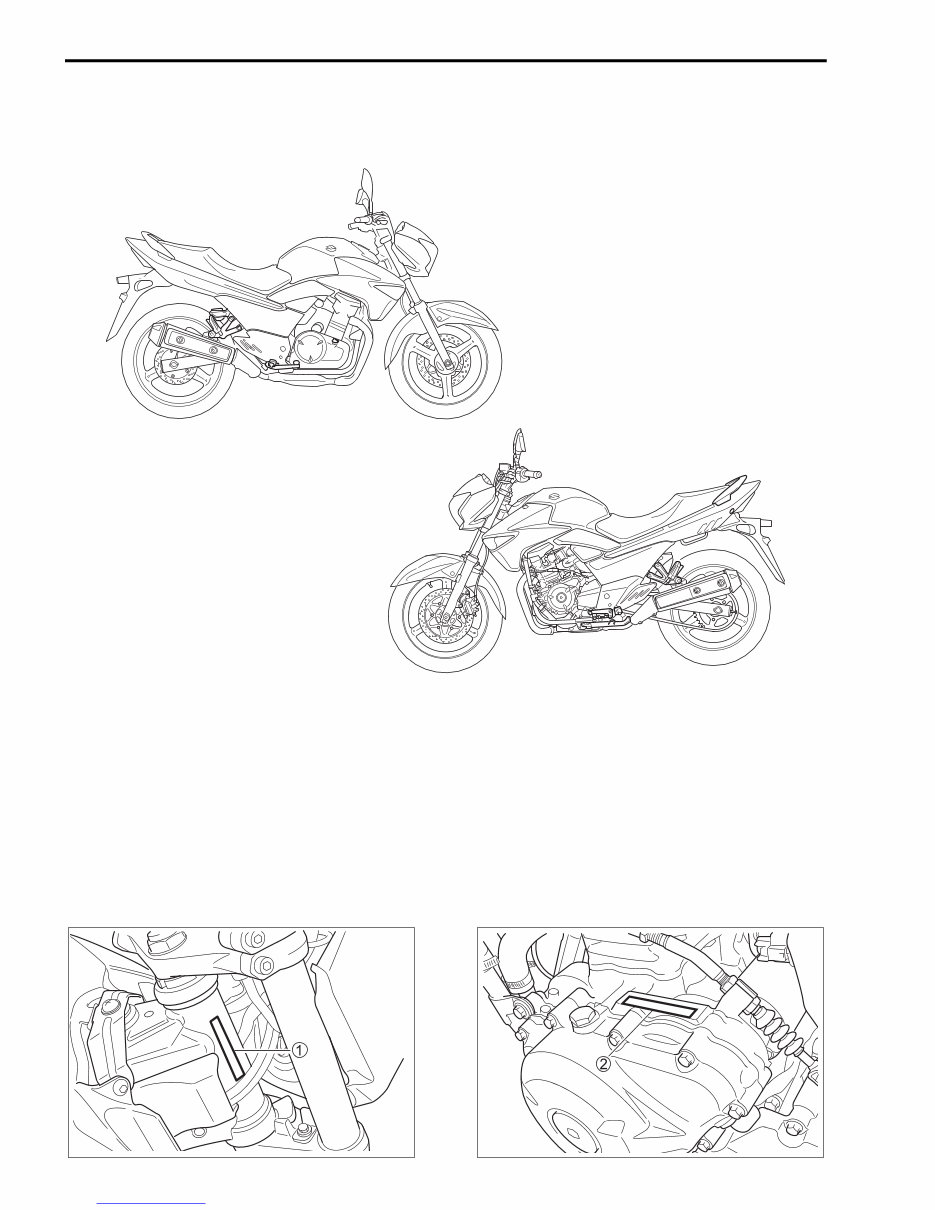
1-4 GENERAL INFORMATION SUZUKI GW250L3 (’13-MODEL) NOTE: Difference between illustration and actual motorcycle may exist depending on the markets. SERIAL NUMBER LOCATION The frame serial number or V.I.N. (Vehicle Identification Number) 1 is stamped on the right side of the steering head pipe. The engine serial number 2 is located on the left side of the crankcase. These numbers are required especially for registering the machine and ordering spare parts. RIGHT SIDE LEFT SIDE Downloaded from www.Manualslib.com manuals search engine
The Suzuki GW250 2012 2013 2014 2015 Workshop Service Manual for Repair is an essential resource for both professional mechanics and DIY enthusiasts. It provides comprehensive data, characteristics, instructions, and methodology for performing repair interventions on the vehicle and its components.
Key features of this manual include:
Special notes, important points, service data, precautions, etc. necessary for maintenance, adjustments, service, removal, and installation of vehicle components
Detailed, comprehensive step-by-step procedures, explanations, and pictorial diagrams from bumper to bumper
Illustrations, exploded diagrams, drawings, and photos to guide through every service repair procedure
Reference to service tool numbers and associated illustrations
General descriptions for accomplishing service and repair work with tested, effective techniques
Information on construction, function, troubleshooting, servicing specifications, tightening torque, checking and adjusting, disassembling, assembling, and servicing
Adjustment and repair operations with reference to wear limits
Procedures for servicing and repairing vehicles using safe, effective methods
Maximizing the life of the vehicle through following maintenance requirements, using genuine parts, and approved lubricants
Technical information regarding design, function, disassembly, adjusting work, and troubleshooting
Valuable reference data for adjustment values
This manual is designed for use by trained technicians in a properly equipped workshop, but contains enough detail and basic information to be useful to owners interested in performing basic maintenance and repair work. It is a complete and intact resource with no missing or corrupt pages/sections.
For all maintenance and repair work, it is essential to strictly observe accident prevention guidelines and follow the procedures outlined in the manual carefully and completely. The manual also provides information about adjusting work and valuable reference data for such adjustment values.
Additionally, it includes specifications, vehicle identification numbers, and detailed information on various components and systems of the Suzuki GW250 2012 2013 2014 2015.
With its precise descriptions supported by photographs, notes, drawings, schematics, exploded and sectional drawings, this manual simplifies necessary repair work on the Suzuki GW250 2012 2013 2014 2015.
It is important to note that this manual is not interactive and is available in .PDF format, suitable for viewing on any computer, and can be zoomed and printed for ease of use.