

2010-2015 Suzuki GSX-R 600 Service & Repair Manual
What's Included?
Fast Download Speeds
Online & Offline Access
Access PDF Contents & Bookmarks
Full Search Facility
Print one or all pages of your manual
SUZUKI
-
SERVICE MANUAL
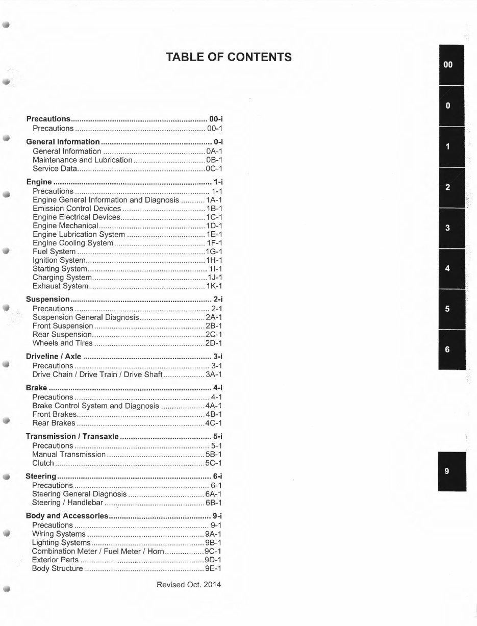
TABLE OF CONTENTS
Precautions ............................................................... 00-i
Precautions ............................................................ 00-1
General Information ......................................... - .......... 0-i
General Information ............................................... OA-1
Maintenance and Lubrication ................................. OB-1
Service Data .................... .. ..................................... OC-1
Engine ......................................................................... 1-i
Precautions .............................................................. 1-1
Engine General Information and Diagnosis ........... 1A-1
Emission Control Devices ...................................... 1 B-1
Engine Electrical Devices ....................................... 1 C-1
Engine Mechanical ................................................. 1 D-1
Engine Lubrication System .................................... 1 E-1
Engine Cooling System .......................................... 1 F-1
Fuel System ........................................................... 1 G-1
Ignition System ....................................................... 1 H-1
Starting System ....................................................... 11-1
Charging System ... .................................................. 1 J-1
Exhaust System ..................................................... 1 K-1
Suspension ................................................................. 2-i
Precautions .............................................................. 2-1
Suspension General Diagnosis .............................. 2A-1
Front Suspension ................................................... 2B-1
Rear Suspension .................................................... 2C-1
Wheels and Tires ............................................ ....... 2D-1
Driveline I Axle ........................................................... 3-i
Precautions .............................................................. 3-1
Drive Chain I Drive Train I Drive Shaft ................... 3A-1
Brake ........................................... .' ............................... 4-i
Precautions ............................................. .. ............... 4-1
Brake Control System and Diagnosis ................... .4A-1
Front Brakes ........................................................... 4B-1
Rear Brakes ........................................................... 4C-1
Transmission I Transaxle .......................................... 5-i
Precautions .............................................................. 5-1
Manual Transmission ............................................. 5B-1
Clutch ..................................................................... 5C-1
Steering ....................................................................... 6-i
Precautions .............................................................. 6-1
Steering General Diagnosis ................................... 6A-1
Steering I Handlebar······:······································· 6B-1
Body and Accessories ............................................... 9-i
Precautions ....................... .. ... .................................. 9-1
Wiring Systems ............... .. ..................................... 9A-1
Lighting Systems .................................................... 9B-1
Combination Meter I Fuel Meter I Horn .................. 9C-1
Exterior Parts ......................................................... 9D-1
Body Structure ....................................................... 9E-1
Revised Oct. 2014
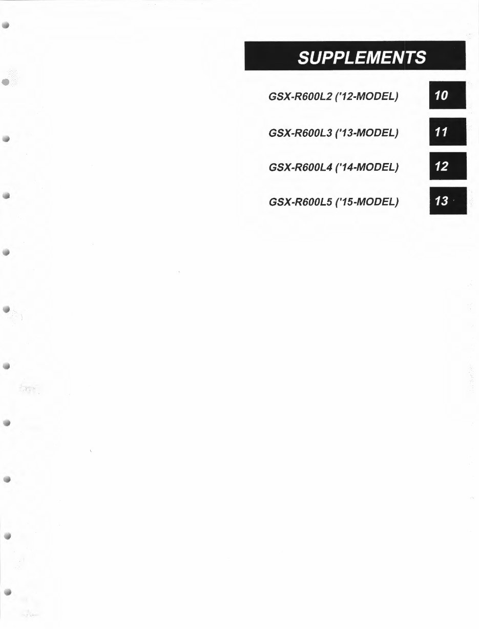
SUPPLEMENTS
GSX-R600L2 ('12-MODEL)
GSX-R600L3 ('13-MODEL)
GSX-R600L4 ('14-MODEL)
GSX-R600L5 ('15-MODEL)
••
Table of Contents 00- i
Section 00
Precautions
CONTENTS
Precautions ............................................... 00-1
General Precautions ........................................... 00-1
Precautions ........................................................... 00-1
Precautions for Electrical Circuit Service ............ 00-2
00-1 Precautions:
Precautions
Precautions
General Precautions
BENB14J20000001
• Proper service and repair procedures are
important for the safety of the service
mechanic and the safety and reliability of
the motorcycle.
• When 2 or more persons work together,
pay attention to the safety of each other.
• When it is necessary to run the engine
indoors, make sure that exhaust gas is
forced outdoors.
• When working with toxic or flammable
materials, make sure that the area you
work in is well ventilated and that you
follow all of the material manufacturer's
instructions.
• Never use gasoline as cleaning solvent.
• To avoid getting burned, do not touch the
engine, engine oil, radiator and exhaust
system until they have cooled.
• After servicing the fuel, oil, water, exhaust
or brake systems, check all lines and
fittings related to the system for leaks.
NOTICE
• If parts replacement is necessary, replace
the parts with Suzuki Genuine Parts or
their equivalent.
• When removing parts that are to be reused,
keep them arranged in an orderly manner
so thatthey may be reinstalled in the
proper order and orientation.
• Be sure to use special tools when
instructed.
• Make sure that all parts used in
reassembly are clean. Lubricate them
when specified.
• Use the specified lubricant, bond or
sealant.
• When removing the battery, disconnect the
negative(-) cable first and then the
positive (+) cable.
• When reconnecting the battery, connect
the positive (+) cable first and then the
negative (-) cable.
• When performing service to electrical
parts, if the service procedures do not
require use of battery power, disconnect
the negative(-) cable the battery.
• When tightening the cylinder head or case
bolts and nuts, tighten the larger sizes
first. Always tighten the bolts and nuts
diagonally from the inside toward outside
and to the specified tightening torque.
• Whenever you remove oil seals, gaskets,
packing, 0-rings, locking washers, self-
locking nuts, cotter pins, circlips and
certain other parts as specified, be sure to
replace them with new ones. Also, before
installing these new parts, be sure to
remove any left over material from the
mating surfaces.
• Never reuse a circlip. When installing a
new circlip, take care not to expand the
end gap larger than required to slip the
circlip over the shaft. After installing a
circlip, always ensure that it is completely
seated in its groove and securely fitted.
• Use a torque wrench to tighten fasteners
to the specified torque. Wipe off grease
and oil if a thread is smeared with them.
• After reassembling, check parts for
tightness and proper operation.
• To protect the environment, do not
unlawfully dispose of used motor oil,
engine coolant and other fluids: batteries,
and tires.
• To protect Earth's natural resources,
properly dispose of used motorcycle and
parts.
Precautions for Electrical Circuit Service
BENB14J20000002
When handling the electrical parts or servicing Fl
system, observe the following points for the safety of the
systems.
Electrical Parts
Connector I Coupler
• Faulty Fl system is often related to poor electrical
contact of connector/coupler. Before servicing
individual electronic part, check electrical contact of
the connector/coupler.
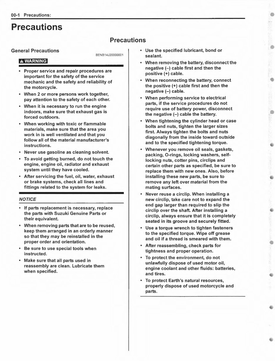
• When connecting a connector, be sure to push it in
until a click is felt.
1310G1000001 -01
• With a lock type coupler, be sure to release the lock
when disconnecting, and push it in fully to engage the
lock when connecting.
• When disconnecting the coupler, be sure to hold the
coupler body and do not pull the lead wires.
• Inspect each terminal on the connector/coupler for
looseness or bending.
• Push in the coupler straightly. An angled or skewed
insertion may cause the terminal to be deformed,
possibly resulting in poor electrical contact.
• Inspect each terminal for corrosion and
contamination. The terminals must be clean and free
of any foreign material which could impede proper
terminal contact.
• Before refitting the sealed coupler, make sure its seal
rubber is positioned properly. The seal rubber may
possibly come off the position during disconnecting
work and if the coupler is refitted with the seal rubber
improperly positioned, it may result in poor water
sealing.
1310G1000002-01
Precautions: 00-2
• Inspect each lead wire circuit for poor connection by
shaking it by hand lightly. If any abnormal condition is
found, repair or replace.
1310G1000003-02
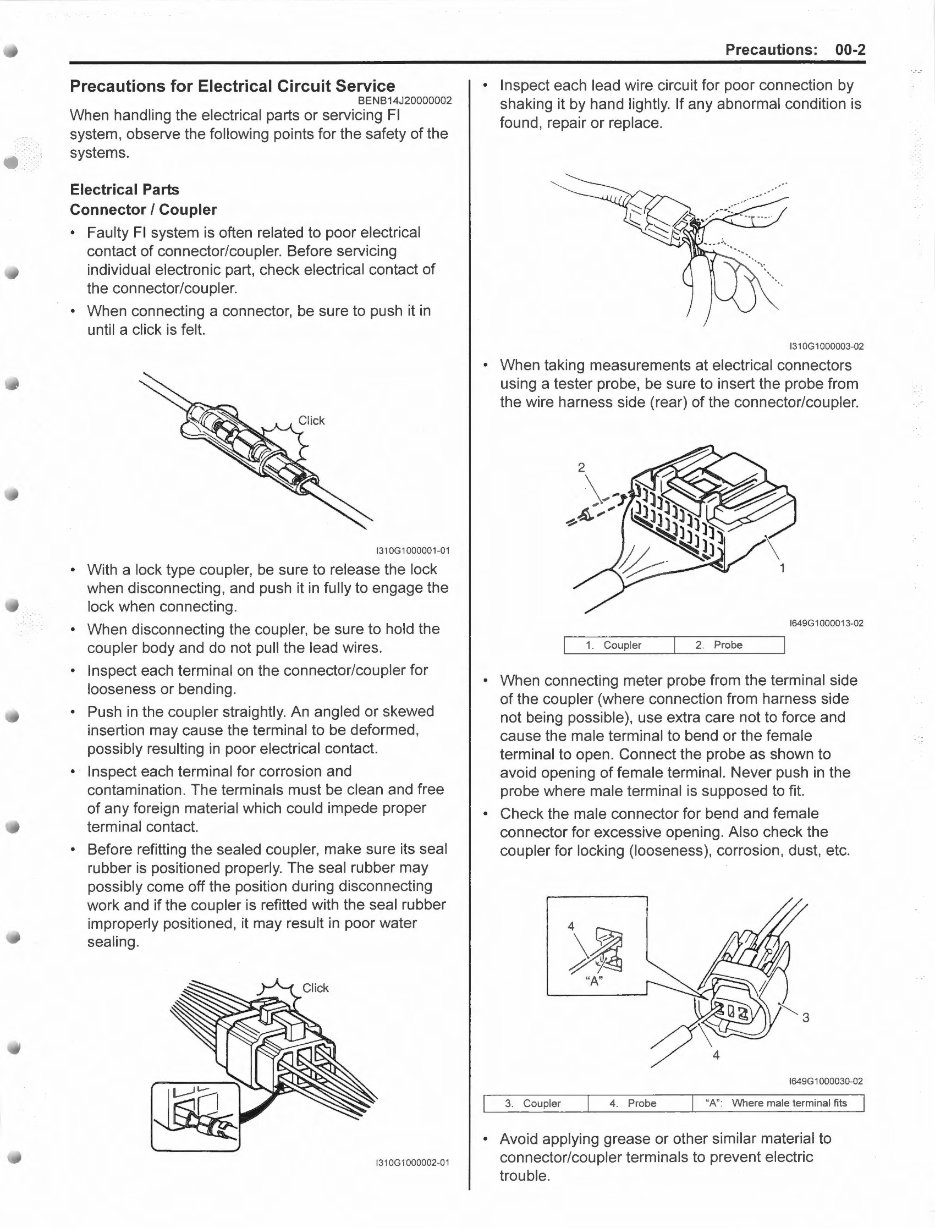
• When taking measurements at electrical connectors
using a tester probe, be sure to insert the probe from
the wire harness side (rear) of the connector/coupler.
1649G1000013-02
1. Coupler 2. Probe
• When connecting meter probe from the terminal side
of the coupler (where connection from harness side
not being possible), use extra care not to force and
cause the male terminal to bend or the female
terminal to open. Connect the probe as shown to
avoid opening of female terminal. Never push in the
probe where male terminal is supposed to fit.
• Check the male connector for bend and female
connector for excessive opening. Also check the
coupler for locking (looseness), corrosion, dust, etc.
4
~
"A"
1649G 1000030-02
3. Coupler 4. Probe "A": Where male terminal fits
• Avoid applying grease or other similar material to
connector/coupler terminals to prevent electric
trouble.
00-3 Precautions:
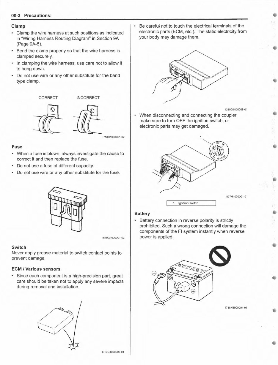
Clamp
• Clamp the wire harness at such positions as indicated
in "Wiring Harness Routing Diagram" in Section 9A
(Page 9A-5).
• Bend the clamp properly so that the wire harness is
clamped securely.
• In clamping the wire harness, use care not to allow it
to hang down.
• Do not use wire or any other substitute for the band
type clamp.
CORRECT INCORRECT
1718H1000001-02
Fuse
• When a fuse is blown, always investigate the cause to
correct it and then replace the fuse.
• Do not use a fuse of different capacity.
• Do not use wire or any other substitute for the fuse.
1649G1000001-02
Switch
Never apply grease material to switch contact points to
prevent damage.
ECM I Various sensors
• Since each component is a high-precision part, great
care should be taken not to apply any severe impacts
during removal and installation.
1310G1000007-01
• Be careful not to touch the electrical terminals of the
electronic parts (ECM, etc.). The static electricity from
your body may damage them.
131OG1000008-01
• When disconnecting and connecting the coupler,
make sure to turn OFF the ignition switch, or
electronic parts may get damaged.
1837H1000001-01
1. Ignition switch
Battery
• Battery connection in reverse polarity is strictly
prohibited. Such a wrong connection will damage the
components of the Fl system instantly when reverse
power is applied.
1718H1000004-01
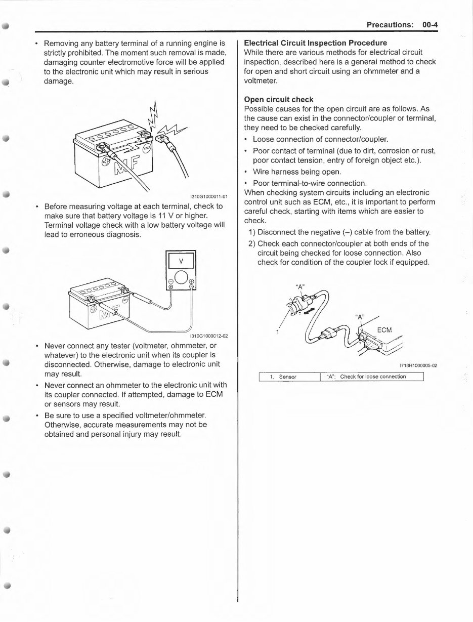
• Removing any battery terminal of a running engine is
strictly prohibited. The moment such removal is made,
damaging counter electromotive force will be applied
to the electronic unit which may result in serious
damage.
1310G1000011-01
• Before measuring voltage at each terminal, check to
make sure that battery voltage is 11 V or higher.
Terminal voltage check with a low battery voltage will
lead to erroneous diagnosis.
1310G1000012-02
• Never connect any tester (voltmeter, ohmmeter, or
whatever) to the electronic unit when its coupler is
disconnected. Otherwise, damage to electronic unit
may result.
• Never connect an ohmmeter to the electronic unit with
its coupler connected. If attempted, damage to ECM
or sensors may result.
• Be sure to use a specified voltmeter/ohmmeter.
Otherwise, accurate measurements may not be
obtained and personal injury may result.
Precautions: 00-4
Electrical Circuit Inspection Procedure
While there are various methods for electrical circuit
inspection, described here is a general method to check
for open and short circuit using an ohmmeter and a
voltmeter.
Open circuit check
Possible causes for the open circuit are as follows. As
the cause can exist in the connector/coupler or terminal,
they need to be checked carefully.
• Loose connection of connector/coupler.
• Poor contact of terminal (due to dirt, corrosion or rust,
poor contact tension, entry of foreign object etc.).
• Wire harness being open.
• Poor terminal-to-wire connection.
When checking system circuits including an electronic
control unit such as ECM, etc., it is important to perform
careful check, starting with items which are easier to
check.
1) Disconnect the negative(-) cable from the battery.
2) Check each connector/coupler at both ends of the
circuit being checked for loose connection. Also
check for condition of the coupler lock if equipped.
"A"
1718H1000005-02
1. Sensor
"A": Check for loose connection
00-5 Precautions:
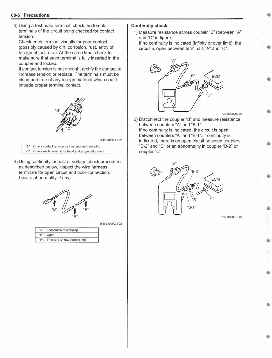
3) Using a test male terminal, check the female
terminals of the circuit being checked for contact
tension.
Check each terminal visually for poor contact
(possibly caused by dirt, corrosion, rust, entry of
foreign object, etc.). At the same time, check to
make sure that each terminal is fully inserted in the
coupler and locked.
If contact tension is not enough, rectify the contact to
increase tension or replace. The terminals must be
clean and free of any foreign material which could
impede proper terminal contact.
1649G1000027-02
"B" : Check contact tension by inserting and removing
"C": Check each terminal for bend and proper alignment
4) Using continuity inspect or voltage check procedure
as described below, inspect the wire harness
terminals for open circuit and poor connection.
Locate abnormality, if any.
"E"
1649G 1000028-02
"D": Looseness of crimping
"E": Open
"F": Thin wire (A few strands left)
Continuity check
1) Measure resistance across coupler "B" (between "A"
and "C" in figure).
If no continuity is indicated (infinity or over limit), the
circuit is open between terminals "A" and "C".
"A"
1705H 1000006-02
2) Disconnect the coupler "B" and measure resistance
between couplers "A" and "B-1 ".
If no continuity is indicated, the circuit is open
between couplers "A" and "B-1". If continuity is
indicated, there is an open circuit between couplers
"B-2" and "C" or an abnormality in coupler "B-2" or
coupler "C".
1705H1000010-02
, .. .
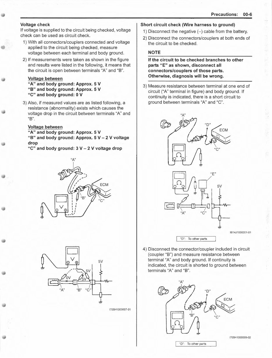
Voltage check
If voltage is supplied to the circuit being checked, voltage
check can be used as circuit check.
1) With all connectors/couplers connected and voltage
applied to the circuit being checked, measure
voltage between each terminal and body ground.
2) If measurements were taken as shown in the figure
and results were listed in the following, it means that
the circuit is open between terminals "A" and "B".
Voltage between
"A" and body ground: Approx. 5 V
"8" and body ground: Approx. 5 V
"C" and body ground: 0 V
3) Also, if measured values are as listed following, a
resistance (abnormality) exists which causes the
voltage drop in the circuit between terminals "A" and
"B".
Voltage between
"A" and body ground: Approx. 5 V
"8" and body ground: Approx. 5 V - 2 V voltage
drop
"C" and body ground: 3 V - 2 V voltage drop
"A"
~l@,._
)JV ft/)
D :0\.·
"A"
I I
I I
I I
l I
__ ,_,
D
"C"
5V
1705H1000007-01
Precautions: 00-6
Short circuit check (Wire harness to ground)
1) Disconnect the negative(-) cable from the battery.
2) Disconnect the connectors/couplers at both ends of
the circuit to be checked.
NOTE
If the circuit to be checked branches to other
parts "E" as shown, disconnect all
connectors/couplers of those parts.
Otherwise, diagnosis will be wrong.
3) Measure resistance between terminal at one end of
circuit ("A" terminal in figure) and body ground. If
continuity is indicated, there is a short circuit to
ground between terminals "A" and "C".
"A"
?~ "D"~
~
.., ECM
I I ~_/
~ / . ~ I
-- ._...~\
D "C"
n. '
IB14J1000001-01
"D": To other parts
4) Disconnect the connector/coupler included in circuit
(coupler "B") and measure resistance between
terminal "A" and body ground. If continuity is
indicated, the circuit is shorted to ground between
terminals "A" and "B".
"A"
?~ "D"
/~ ~
I ... ECM
L~~ l~~
D "B" \
"C"
(')_
1705H 1000009-02
"D": To other parts
You're Reading a Preview
What's Included?
Fast Download Speeds
Online & Offline Access
Access PDF Contents & Bookmarks
Full Search Facility
Print one or all pages of your manual
$31.99
$41.99
Viewed 56 Times Today


Secure transaction
What's Included?
Fast Download Speeds
Online & Offline Access
Access PDF Contents & Bookmarks
Full Search Facility
Print one or all pages of your manual
$31.99
$41.99
Get instant access to the Complete Factory Service Repair Workshop Manual without any extra fees or expiry dates. This Professional Manual is suitable for both professional Mechanics and DIY enthusiasts, covering all repairs, servicing, and troubleshooting procedures with step-by-step instructions, detailed photos, diagrams, and highly detailed exploded diagrams & pictures.
Print out a single page or the entire manual as per your choice. The Manual can be used on multiple computers without any limitations or trial periods and can be used for life without the need to renew or pay any extra. It is fully compatible with all Windows & MAC Computers.
Click the button to get your hands on this comprehensive manual.


