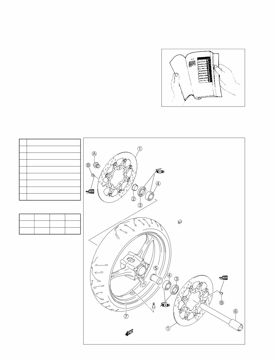
HOW TO USE THIS MANUAL TO LOCATE WHAT YOU ARE LOOKING FOR: 1. The text of this manual is divided into sections. 2. The section titles are listed in the GROUP INDEX. 3. Holding the manual as shown at the right will allow you to find the first page of the section easily. 4. The contents are listed on the first page of each section to help you find the item and page you need. COMPONENT PARTS AND WORK TO BE DONE Under the name of each system or unit, is its exploded view. Work instructions and other service information such as the tightening torque, lubricating points and locking agent points, are provided. Example: Front wheel 1 Brake disc 2 Collar 3 Dust seal 4 Bearing 5 Spacer 6 Front axle 7 Front wheel A Front axle bolt B Brake disc bolt ITEM N·m kgf-m lb-ft A 100 10.0 72.5 B 23 2.3 16.5
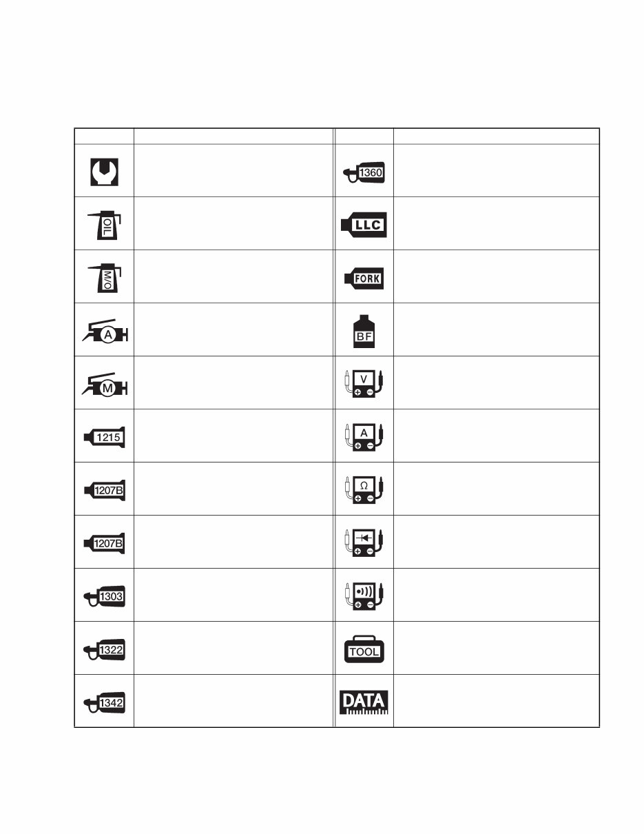
SYMBOL Listed in the table below are the symbols indicating instructions and other information necessary for servic- ing. The meaning of each symbol is also included in the table. SYMBOL DEFINITION SYMBOL DEFINITION Torque control required. Data beside it indicates specified torque. Apply THREAD LOCK SUPER “1360”. 99000-32130 Apply oil. Use engine oil unless other- wise specified. Use engine coolant. 99000-99032-11X (Except USA) Apply molybdenum oil solution. (Mixture of engine oil and SUZUKI MOLY PASTE in a ratio of 1:1) Use fork oil. 99000-99001-SS5 Apply SUZUKI SUPER GREASE “A” or equivalent grease. 99000-25010 Apply or use brake fluid. Apply SUZUKI MOLY PASTE. 99000-25140 Measure in voltage range. Apply SUZUKI BOND “1215” or equivalent bond. 99000-31110 Measure in current range. Apply SUZUKI BOND “1207B”. 99104-31140 (USA) Measure in resistance range. Apply SUZUKI BOND “1207B”. 99000-31140 (Except USA) Measure in diode test range. Apply THREAD LOCK SUPER “1303”. 99000-32030 Measure in continuity test range. Apply THREAD LOCK SUPER “1322” or equivalent thread lock. 99000-32110 Use special tool. Apply THREAD LOCK “1342”. 99000-32050 Indication of service data.
ABBREVIATIONS USED IN THIS MANUAL A ABDC : After Bottom Dead Center AC : Alternating Current ACL : Air Cleaner, Air Cleaner Box API : American Petroleum Institute ATDC : After Top Dead Center ATM Pressure : Atmospheric Pressure : Atmospheric Pressure sensor (APS, AP Sensor) A/F : Air Fuel Mixture B BBDC : Before Bottom Dead Center BTDC : Before Top Dead Center B+ : Battery Positive Voltage C CKP Sensor : Crankshaft Position Sensor (CKPS) CKT : Circuit CLP Switch : Clutch Lever Position Switch (Clutch Switch) CMP Sensor : Camshaft Position Sensor (CMPS) CO : Carbon Monoxide CPU : Central Processing Unit D DC : Direct Current DMC : Dealer Mode Coupler DOHC : Double Over Head Camshaft DRL : Daytime Running Light DTC : Diagnostic Trouble Code E ECM : Engine Control Module Engine Control Unit (ECU) (FI Control Unit) ECT Sensor : Engine Coolant Temperature Sensor (ECTS), Water Temp. Sensor (WTS) EVAP : Evaporative Emission EVAP Canister : Evaporative Emission Canister (Canister) EXC System : Exhaust Control System (EXCS) EXC Valve : Exhaust Control Valve (EXCV) EXCV Actuator : Exhaust Control Valve Actuator (EXCVA) F FI : Fuel Injection, Fuel Injector FP : Fuel Pump FPR : Fuel Pressure Regulator FP Relay : Fuel Pump Relay G GEN : Generator GND : Ground GP Switch : Gear Position Switch H HC : Hydrocarbons I IAP Sensor : Intake Air Pressure Sensor (IAPS) (MAP Sensor) IAT Sensor : Intake Air Temperature Sensor (IATS) IG : Ignition L LCD : Liquid Crystal Display LED : Light Emitting Diode (Malfunction Indicator Lamp) LH : Left Hand
M MAL-Code : Malfunction Code (Diagnostic Code) Max : Maximum MIL : Malfunction Indicator Lamp (LED) Min : Minimum N NOX : Nitrogen Oxides O OHC : Over Head Camshaft OPS : Oil Pressure Switch P PCV : Positive Crankcase Ventilation (Crankcase Breather) R RH : Right Hand ROM : Read Only Memory S SAE : Society of Automotive Engineers SDS : Suzuki Diagnosis System STC System : Secondary Throttle Control System (STCS) STP Sensor : Secondary Throttle Position Sensor (STPS) ST Valve : Secondary Throttle Valve (STV) STV Actuator : Secondary Throttle Valve Actuator (STVA) T TO Sensor : Tip-Over Sensor (TOS) TP Sensor : Throttle Position Sensor (TPS)
WIRE COLOR B : Black G : Green P :Pink Bl : Blue Gr : Gray R : Red Br : Brown Lbl : Light blue W : White Dg : Dark green Lg : Light green Y : Yellow Dgr : Dark gray O : Orange B/Bl : Black with Blue tracer B/Br : Black with Brown tracer B/G : Black with Green tracer B/Lg : Black with Light green tracer B/R : Black with Red tracer B/W : Black with White tracer B/Y : Black with Yellow tracer Bl/B : Blue with Black tracer Bl/G : Blue with Green tracer Bl/R : Blue with Red tracer Bl/W : Blue with White tracer Bl/Y : Blue with Yellow tracer Br/Y : Brown with Yellow tracer G/B : Green with Black tracer G/Bl : Green with Blue tracer G/R : Green with Red tracer G/W : Green with White tracer G/Y : Green with Yellow tracer Gr/B : Gray with Black tracer Gr/R : Gray with Red tracer Gr/W : Gray with White tracer Gr/Y : Gray with Yellow tracer Lg/BI : Light green with Blue tracer Lg/G : Light green with Green tracer Lg/W : Light green with White tracer O/B : Orange with Black tracer O/BI : Orange with Blue tracer O/G : Orange with Green tracer O/R : Orange with Red tracer O/W : Orange with White tracer O/Y : Orange with Yellow tracer P/B : Pink with Black tracer P/W : Pink with White tracer R/B : Red with Black tracer R/Bl : Red with Blue tracer R/Y : Red with Yellow tracer R/W : Red with White tracer W/B : White with Black tracer W/Bl : White with Blue tracer W/G : White with Green tracer W/R : White with Red tracer W/Y : White with Yellow tracer Y/B : Yellow with Black tracer Y/Bl : Yellow with Blue tracer Y/G : Yellow with Green tracer Y/R : Yellow with Red tracer Y/W : Yellow with White tracer
GENERAL INFORMATION 1-1 1 GENERAL INFORMATION CONTENTS WARNING/CAUTION/NOTE ......................................................................... 1- 2 GENERAL PRECAUTIONS .......................................................................... 1- 2 SUZUKI GSX-R600K6 (’06-MODEL) ............................................................ 1- 4 SERIAL NUMBER LOCATION ..................................................................... 1- 4 FUEL, OIL AND ENGINE COOLANT RECOMMENDATION ....................... 1- 5 FUEL (FOR USA AND CANADA) .......................................................... 1- 5 FUEL (FOR OTHER COUNTRIES) ........................................................ 1- 5 ENGINE OIL (FOR USA) ........................................................................ 1- 5 ENGINE OIL (FOR OTHER COUNTRIES)............................................. 1- 5 BRAKE FLUID ........................................................................................ 1- 5 FRONT FORK OIL.................................................................................. 1- 6 ENGINE COOLANT................................................................................ 1- 6 WATER FOR MIXING............................................................................. 1- 6 ANTI-FREEZE/ENGINE COOLANT ....................................................... 1- 6 LIQUID AMOUNT OF WATER/ENGINE COOLANT ............................. 1- 6 BREAK-IN PROCEDURES ........................................................................... 1- 7 CYLINDER IDENTIFICATION....................................................................... 1- 7 INFORMATION LABELS .............................................................................. 1- 8 SPECIFICATIONS......................................................................................... 1- 9 DIMENSIONS AND DRY MASS............................................................. 1- 9 ENGINE .................................................................................................. 1- 9 DRIVE TRAIN ......................................................................................... 1- 9 CHASSIS ................................................................................................ 1-10 ELECTRICAL ......................................................................................... 1-10 CAPACITIES .......................................................................................... 1-10 COUNTRY AND AREA CODES The following codes stand for the applicable country(-ies) and area(-s). CODE COUNTRY or AREA EFFECTIVE FRAME NO. E-02 E-19 (GSX-R600) E-19 (GSX-R600U2) E-19 (GSX-R600U3) E-24 E-03 E-28 E-33 U.K. E.U. E.U. E.U. Australia U.S.A. (Except for California) Canada California (U.S.A.) JS1CE111100100001 – JS1CE111100100001 – JS1CE211100100001 – JS1CE311100100001 – JS1CE121300100001 – JS1GN7DA 62100001 – JS1GN7DA 62100001 – JS1GN7DA 62100001 –
1-2 GENERAL INFORMATION WARNING/CAUTION/NOTE Please read this manual and follow its instructions carefully. To emphasize special information, the symbol and the words WARNING, CAUTION and NOTE have special meanings. Pay special attention to the mes- sages highlighted by these signal words. Indicates a potential hazard that could result in death or injury. Indicates a potential hazard that could result in motorcycle damage. NOTE: Indicates special information to make maintenance easier or instructions clearer. Please note, however, that the warnings and cautions contained in this manual cannot possibly cover all potential hazards relating to the servicing, or lack of servicing, of the motorcycle. In addition to the WARN- INGS and CAUTIONS stated, you must use good judgement and basic mechanical safety principles. If you are unsure about how to perform a particular service operation, ask a more experienced mechanic for advice. GENERAL PRECAUTIONS * Proper service and repair procedures are important for the safety of the service mechanic and the safety and reliability of the motorcycle. * When 2 or more persons work together, pay attention to the safety of each other. * When it is necessary to run the engine indoors, make sure that exhaust gas is forced out- doors. * When working with toxic or flammable materials, make sure that the area you work in is well- ventilated and that you follow all of the material manufacturer’s instructions. * Never use gasoline as a cleaning solvent. * To avoid getting burned, do not touch the engine, engine oil, radiator and exhaust system until they have cooled. After servicing the fuel, oil, water, exhaust or brake systems, check all lines and fittings related to the system for leaks.
GENERAL INFORMATION 1-3 * If parts replacement is necessary, replace the parts with Suzuki Genuine Parts or their equiva- lent. * When removing parts that are to be reused, keep them arranged in an orderly manner so that they may be reinstalled in the proper order and orientation. * Be sure to use special tools when instructed. * Make sure that all parts used in reassembly are clean. Lubricate them when specified. * Use the specified lubricant, bond, or sealant. * When removing the battery, disconnect the negative cable first and then the positive cable. * When reconnecting the battery, connect the positive cable first and then the negative cable, and replace the terminal cover on the positive terminal. * When performing service to electrical parts, if the service procedures do not require use of battery power, disconnect the negative cable from the battery. * When tightening the cylinder head or case bolts and nuts, tighten the larger sizes first. Always tighten the bolts and nuts diagonally from the inside toward outside and to the speci- fied tightening torque. * Whenever you remove oil seals, gaskets, packing, O-rings, locking washers, self-locking nuts, cotter pins, circlips and certain other parts as specified, be sure to replace them with new ones. Also, before installing these new parts, be sure to remove any left over material from the mating surfaces. * Never reuse a circlip. When installing a new circlip, take care not to expand the end gap larger than required to slip the circlip over the shaft. After installing a circlip, always ensure that it is completely seated in its groove and securely fitted. * Use a torque wrench to tighten fasteners to the specified torque. Wipe off grease and oil if a thread is smeared with them. * After reassembling, check parts for tightness and proper operation. * To protect the environment, do not unlawfully dispose of used motor oil, engine coolant and other fluids: batteries and tires. * To protect Earth’s natural resources, properly dispose of used motorcycle and parts.
This is the complete 2006-2007 SUZUKI GSX-R600 Repair Manual, including a Parts Manual. It is a model-specific service manual consisting of 520 pages with detailed pictures, diagrams, and step-by-step procedures covering the entire 2006-2007 GSX-R600. The manual also includes a 98-page Exploded Parts Diagrams and Part Numbers Fische. Both the Repair Manual and the Parts Manual are fully indexed and detailed bookmarked, with clickable chapter contents. The document is in Adobe PDF format, allowing for high-quality printing and clear viewing. It is searchable by keywords, enabling easy access to specific information. Additionally, the manual includes a Wiring Diagram Schematic and Troubleshooting Guides. This comprehensive service manual package covers all servicing topics for the 2006-2007 SUZUKI GSX-R600, making it suitable for professional mechanics and DIY enthusiasts alike.
Thank you for considering this 2006-2007 SUZUKI GSX-R600 SERVICE MANUAL.
Recently Viewed
5,521,897Happy Clients
2,594,462eManuals
1,120,453Trusted Sellers
15Years in Business
Price:
Actual Price:
2006-2007 SUZUKI GSX-R600 Service Manual Repair Manual and Parts Manual