

Suzuki GSXR 1000 K5 K6 service manual
What's Included?
Fast Download Speeds
Online & Offline Access
Access PDF Contents & Bookmarks
Full Search Facility
Print one or all pages of your manual

99500-39270-01E
GSX-R1000
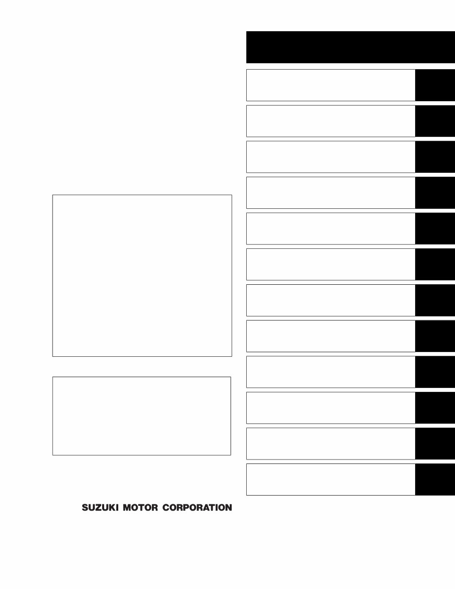
GROUP INDEX
GENERAL INFORMATION
1
PERIODIC MAINTENANCE
2
ENGINE
3
FI SYSTEM DIAGNOSIS
4
FUEL SYSTEM AND THROTTLE
BODY
5
EXHAUST SYSTEM
6
COOLING AND LUBRICATION
SYSTEM
7
CHASSIS
8
ELECTRICAL SYSTEM
9
SERVICING INFORMATION
10
EMISSION CONTROL
INFORMATION
11
WIRING DIAGRAM
12
FOREWORD
This manual contains an introductory description on
the SUZUKI GSX-R1000 and procedures for its
inspection/service and overhaul of its main compo-
nents.
Other information considered as generally known is
not included.
Read the GENERAL INFORMATION section to
familiarize yourself with the motorcycle and its main-
tenance. Use this section as well as other sections
to use as a guide for proper inspection and service.
This manual will help you know the motorcycle bet-
ter so that you can assure your customers of fast
and reliable service.
© COPYRIGHT SUZUKI MOTOR CORPORATION 2005
* This manual has been prepared on the basis
of the latest specifications at the time of publi-
cation. If modifications have been made since
then, differences may exist between the con-
tent of this manual and the actual motorcycle.
* Illustrations in this manual are used to show
the basic principles of operation and work
procedures. They may not represent the
actual motorcycle exactly in detail.
* This manual is written for persons who have
enough knowledge, skills and tools, including
special tools, for servicing SUZUKI motorcy-
cles. If you do not have the proper knowledge
and tools, ask your authorized SUZUKI
motorcycle dealer to help you.
Inexperienced mechanics or mechanics
without the proper tools and equipment
may not be able to properly perform the
services described in this manual.
Improper repair may result in injury to the
mechanic and may render the motorcycle
unsafe for the rider and passenger.
SAMPLE
HOW TO USE THIS MANUAL
TO LOCATE WHAT YOU ARE LOOKING FOR:
1. The text of this manual is divided into sections.
2. The section titles are listed in the GROUP INDEX.
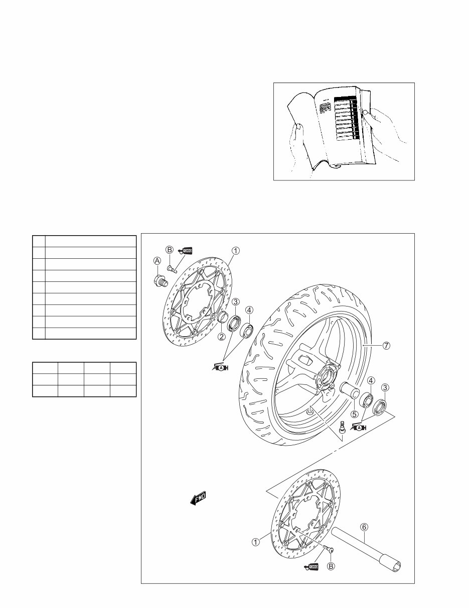
3. Holding the manual as shown at the right will allow you to find
the first page of the section easily.
4. The contents are listed on the first page of each section to
help you find the item and page you need.
COMPONENT PARTS AND WORK TO BE DONE
Under the name of each system or unit, is its exploded view. Work instructions and other service information
such as the tightening torque, lubricating points and locking agent points, are provided.
Example: Front wheel
1 Brake disc
2 Collar
3 Dust seal
4 Bearing
5 Spacer
6 Front axle
7 Front wheel
A Front axle bolt
B Brake disc bolt
ITEM N·m kgf-m lb-ft
A 100 10.0 72.5
B 23 2.3 16.5
SAMPLE
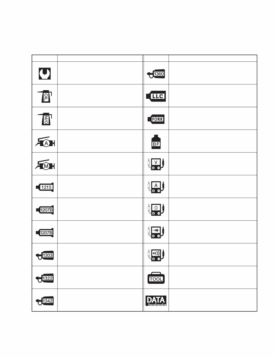
SYMBOL
Listed in the table below are the symbols indicating instructions and other information necessary for servic-
ing. The meaning of each symbol is also included in the table.
SYMBOL DEFINITION SYMBOL DEFINITION
Torque control required.
Data beside it indicates specified
torque.
Apply THREAD LOCK SUPER “1360”.
99000-32130
Apply oil. Use engine oil unless other-
wise specified.
Use engine coolant.
99000-99032-11X (Except USA)
Apply molybdenum oil solution.
(Mixture of engine oil and SUZUKI
MOLY PASTE in a ratio of 1:1)
Use fork oil.
99000-99044-L01
Apply SUZUKI SUPER GREASE “A”.
99000-25010 (Others)
99000-25030 (USA)
Apply or use brake fluid.
Apply SUZUKI MOLY PASTE.
99000-25140
Measure in voltage range.
Apply SUZUKI BOND “1215”.
99000-31110 (Except USA)
Measure in current range.
Apply SUZUKI BOND “1207B”.
99104-31140 (USA)
Measure in resistance range.
Apply SUZUKI BOND “1207B”.
99000-31140 (Except USA)
Measure in diode test range.
Apply THREAD LOCK SUPER “1303”.
99000-32030
Measure in continuity test range.
Apply THREAD LOCK SUPER “1322”.
99000-32110 (Except USA)
Use special tool.
Apply THREAD LOCK “1342”.
99000-32050 (USA)
Indication of service data.
SAMPLE

ABBREVIATIONS USED IN THIS
MANUAL
A
ABDC : After Bottom Dead Center
AC : Alternating Current
ACL : Air Cleaner, Air Cleaner Box
API : American Petroleum Institute
ATDC : After Top Dead Center
ATM Pressure : Atmospheric Pressure
: Atmospheric Pressure sensor
(APS, AP Sensor)
A/F : Air Fuel Mixture
B
BBDC : Before Bottom Dead Center
BTDC : Before Top Dead Center
B+ : Battery Positive Voltage
C
CKP Sensor : Crankshaft Position Sensor
(CKPS)
CKT : Circuit
CLP Switch : Clutch Lever Position Switch
(Clutch Switch)
CMP Sensor : Camshaft Position Sensor
(CMPS)
CO : Carbon Monoxide
CPU : Central Processing Unit
D
DC : Direct Current
DMC : Dealer Mode Coupler
DOHC : Double Over Head Camshaft
DRL : Daytime Running Light
DTC : Diagnostic Trouble Code
E
ECM : Engine Control Module
Engine Control Unit (ECU)
(FI Control Unit)
ECT Sensor : Engine Coolant Temperature
Sensor (ECTS), Water Temp.
Sensor (WTS)
EVAP : Evaporative Emission
EVAP Canister : Evaporative Emission
Canister (Canister)
EXC System : Exhaust Control System (EXCS)
EXC Valve : Exhaust Control Valve (EXCV)
EXCV Actuator : Exhaust Control Valve Actuator
(EXCVA)
F
FI : Fuel Injection, Fuel Injector
FP : Fuel Pump
FPR : Fuel Pressure Regulator
FP Relay : Fuel Pump Relay
G
GEN : Generator
GND : Ground
GP Switch : Gear Position Switch
H
HC : Hydrocarbons
I
IAP Sensor : Intake Air Pressure Sensor (IAPS)
(MAP Sensor)
IAT Sensor : Intake Air Temperature Sensor
(IATS)
IG : Ignition
L
LCD : Liquid Crystal Display
LED : Light Emitting Diode
(Malfunction Indicator Lamp)
LH : Left Hand
SAMPLE

M
MAL-Code : Malfunction Code
(Diagnostic Code)
Max : Maximum
MIL : Malfunction Indicator Lamp
(LED)
Min : Minimum
N
NOX : Nitrogen Oxides
O
OHC : Over Head Camshaft
OPS : Oil Pressure Switch
P
PCV : Positive Crankcase
Ventilation (Crankcase Breather)
R
RH : Right Hand
ROM : Read Only Memory
S
SAE : Society of Automotive Engineers
SDS : Suzuki Diagnosis System
STC System : Secondary Throttle Control System
(STCS)
STP Sensor : Secondary Throttle Position Sensor
(STPS)
ST Valve : Secondary Throttle Valve (STV)
STV Actuator : Secondary Throttle Valve Actuator
(STVA)
T
TO Sensor : Tip-Over Sensor (TOS)
TP Sensor : Throttle Position Sensor (TPS)
SAMPLE

WIRE COLOR
B : Black G : Green P :Pink
Bl : Blue Gr : Gray R : Red
Br : Brown Lbl : Light blue W : White
Dg : Dark green Lg : Light green Y : Yellow
Dgr : Dark gray O : Orange
B/Bl : Black with Blue tracer B/Br : Black with Brown tracer
B/G : Black with Green tracer B/Lg : Black with Light green tracer
B/R : Black with Red tracer B/W : Black with White tracer
B/Y : Black with Yellow tracer Bl/B : Blue with Black tracer
Bl/G : Blue with Green tracer Bl/R : Blue with Red tracer
Bl/W : Blue with White tracer Bl/Y : Blue with Yellow tracer
Br/Y : Brown with Yellow tracer G/B : Green with Black tracer
G/Bl : Green with Blue tracer G/R : Green with Red tracer
G/W : Green with White tracer G/Y : Green with Yellow tracer
Gr/B : Gray with Black tracer Gr/R : Gray with Red tracer
Gr/W : Gray with White tracer Gr/Y : Gray with Yellow tracer
Lg/BI : Light green with Blue tracer Lg/G : Light green with Green tracer
Lg/W : Light green with White tracer O/B : Orange with Black tracer
O/BI : Orange with Blue tracer O/G : Orange with Green tracer
O/R : Orange with Red tracer O/W : Orange with White tracer
O/Y : Orange with Yellow tracer P/B : Pink with Black tracer
P/W : Pink with White tracer R/B : Red with Black tracer
R/Bl : Red with Blue tracer R/Y : Red with Yellow tracer
R/W : Red with White tracer W/B : White with Black tracer
W/Bl : White with Blue tracer W/G : White with Green tracer
W/R : White with Red tracer W/Y : White with Yellow tracer
Y/B : Yellow with Black tracer Y/Bl : Yellow with Blue tracer
Y/G : Yellow with Green tracer Y/R : Yellow with Red tracer
Y/W : Yellow with White tracer
SAMPLE
GENERAL INFORMATION 1-1
1
GENERAL INFORMATION
CONTENTS
WARNING/CAUTION/NOTE ......................................................................... 1- 2
GENERAL PRECAUTIONS .......................................................................... 1- 2
SUZUKI GSX-R1000K5 (’05-MODEL) .......................................................... 1- 4
SERIAL NUMBER LOCATION ..................................................................... 1- 4
FUEL, OIL AND ENGINE COOLANT RECOMMENDATION ....................... 1- 5
FUEL (FOR USA AND CANADA) .......................................................... 1- 5
FUEL (FOR OTHER COUNTRIES) ........................................................ 1- 5
ENGINE OIL (FOR USA) ........................................................................ 1- 5
ENGINE OIL (FOR OTHER COUNTRIES) ............................................. 1- 5
BRAKE FLUID ........................................................................................ 1- 5
FRONT FORK OIL.................................................................................. 1- 6
ENGINE COOLANT................................................................................ 1- 6
WATER FOR MIXING............................................................................. 1- 6
ANTI-FREEZE/ENGINE COOLANT ....................................................... 1- 6
LIQUID AMOUNT OF WATER/ENGINE COOLANT ............................. 1- 6
BREAK-IN PROCEDURES ........................................................................... 1- 7
CYLINDER IDENTIFICATION....................................................................... 1- 7
INFORMATION LABELS .............................................................................. 1- 8
SPECIFICATIONS......................................................................................... 1- 9
DIMENSIONS AND DRY MASS............................................................. 1- 9
ENGINE .................................................................................................. 1- 9
DRIVE TRAIN ......................................................................................... 1- 9
CHASSIS ................................................................................................ 1-10
ELECTRICAL ......................................................................................... 1-10
CAPACITIES .......................................................................................... 1-10
COUNTRY AND AREA CODES
The following codes stand for the applicable country(-ies) and area(-s).
CODE COUNTRY or AREA EFFECTIVE FRAME NO.
E-02
E-03
E-19 (GSX-R1000)
E-19 (GSX-R1000UF)
E-24
E-28
E-33
U.K.
U.S.A. (Except for California)
E.U.
E.U.
Australia
Canada
California (U.S.A.)
JS1B6111200100001 –
JS1GT76A 52100001 –
JS1B6111100100001 –
JS1B6211100100001 –
JS1B6121300100001 –
JS1GT76A 52100001 –
JS1GT76A 52100001 –
SAMPLE

1-2 GENERAL INFORMATION
WARNING/CAUTION/NOTE
Please read this manual and follow its instructions carefully. To emphasize special information, the symbol
and the words WARNING, CAUTION and NOTE have special meanings. Pay special attention to the mes-
sages highlighted by these signal words.
Indicates a potential hazard that could result in death or injury.
Indicates a potential hazard that could result in motorcycle damage.
NOTE:
Indicates special information to make maintenance easier or instructions clearer.
Please note, however, that the warnings and cautions contained in this manual cannot possibly cover all
potential hazards relating to the servicing, or lack of servicing, of the motorcycle. In addition to the WARN-
INGS and CAUTIONS stated, you must use good judgement and basic mechanical safety principles. If you
are unsure about how to perform a particular service operation, ask a more experienced mechanic for
advice.
GENERAL PRECAUTIONS
* Proper service and repair procedures are important for the safety of the service mechanic and
the safety and reliability of the motorcycle.
* When 2 or more persons work together, pay attention to the safety of each other.
* When it is necessary to run the engine indoors, make sure that exhaust gas is forced out-
doors.
* When working with toxic or flammable materials, make sure that the area you work in is well-
ventilated and that you follow all of the material manufacturer’s instructions.
* Never use gasoline as a cleaning solvent.
* To avoid getting burned, do not touch the engine, engine oil, radiator and exhaust system
until they have cooled.
After servicing the fuel, oil, water, exhaust or brake systems, check all lines and fittings related
to the system for leaks.
SAMPLE
You're Reading a Preview
What's Included?
Fast Download Speeds
Online & Offline Access
Access PDF Contents & Bookmarks
Full Search Facility
Print one or all pages of your manual
$28.99
Viewed 68 Times Today


Secure transaction
What's Included?
Fast Download Speeds
Online & Offline Access
Access PDF Contents & Bookmarks
Full Search Facility
Print one or all pages of your manual
$28.99
The Suzuki GSXR 1000 K5 K6 service manual provides essential information for both professional mechanics and DIY enthusiasts. It covers a wide range of topics, including precautions, general information, maintenance, lubrication, service data, engine, suspension, driveline/axle, brake, transmission/transaxle, clutch, steering, and body and accessories.
- Precautions
- General Information
- Maintenance and Lubrication
- Service Data
- Engine
- General Information and Diagnosis
- Emission Control Devices
- Engine Electrical Devices
- Engine Mechanical
- Engine Lubrication System
- Engine Cooling System
- Fuel System
- Ignition System
- Starting System
- Charging System
- Exhaust System
- Suspension
- Suspension General Diagnosis
- Front Suspension
- Rear Suspension
- Wheels and Tires
- Driveline / Axle
- Drive Chain / Drive Train / Drive Shaft
- Brake
- Brake Control System and Diagnosis
- Front Brakes
- Rear Brakes
- Transmission / Transaxle
- Manual Transmission
- Clutch
- Steering
- Steering General Diagnosis
- Steering / Handlebar
- Body and Accessories
- Wiring Systems
- Lighting Systems
- Combination Meter / Fuel Meter / Horn
- Exterior Parts
- Body Structure
Whether you need to perform routine maintenance or complex repairs, this manual is a valuable resource for maintaining and servicing the Suzuki GSXR 1000 K5 K6.


