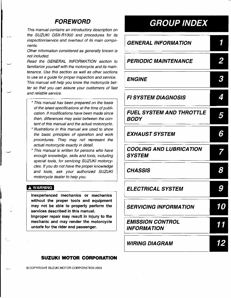
HOW TO USE THIS MANUAL TO LOCATE WHAT YOU ARE LOOKING FOR: 1. The text of this manual is divided into sections. 2. The section titles are listed in the GROUP INDEX. 3. Holding the manual as shown at the right will allow you to find the first page of the section easily. 4. The contents are listed on the first page of each section to help you find the item and page you need. \ \ \,--- COMPONENT PARTS AND WORK TO BE DONE Under the name of each system or unit, is its exploded view. Work instructions and other service information such as the tightening torque, lubricating points and locking agent points, are provided. Example: Front wheel CD Brake disc ~ Dust seal @ Bearing @ Spacer @ Spacer nut @ Front wheel ® Front axle ® Brake disc bolt (Front) -- r!J - ITEM N·m kgf-m Ib-ft ® 100 10.0 72.5 ~ ® 23 2.3 16.5
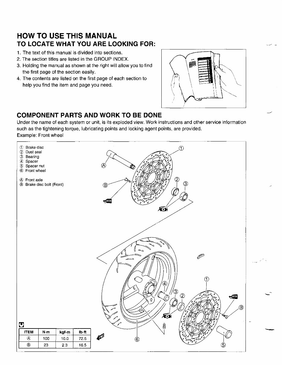
SYMBOL Listed in the table below are the symbols indicating instructions and other information necessary for servic- ing. The meaning of each symbol is also included in the table. SYMBOL DEFINITION SYMBOL DEFINITION ~ Torque control required. • Apply THREAD LOCK SUPER "1360". Data beside it indicates specified 99000-32130 torque. l!r Apply oil. Use engine oil unless other- e Use engine coolant. wise specified. lIr Apply molybdenum oil solution. e Use fork oil. (Mixture of engine oil and SUZUKI 99000-99044-LO1 MOLY PASTE in a ratio of 1:1) ~ Apply SUZUKI SUPER GREASE "A". I 99000-25010 (Others) Apply or use brake fluid. 99000-25030 (USA) ~ Apply SUZUKI MOLY PASTE. ~ Measure in voltage range. 99000-25140 €i]J Apply SUZUKI BOND "1215". ~ Measure in current range. 99000-31110 (Except USA) -41207~ Apply SUZUKI BOND "1207B". ~ Measure in resistance range. 99104-31140 (USA) -41207~ Apply SUZUKI BOND "1207B". ~ Measure in diode test range. 99000-31140 (Except USA) ~ Apply THREAD LOCK SUPER "1303". ~ Measure in continuity test range. 99000-32030 • Apply THREAD LOCK SUPER "1322". l+ooLI Use special tool. 99000-32110 (Except USA) • Apply THREAD LOCK "1342". - Indication of service data. 99000-32050 (USA)
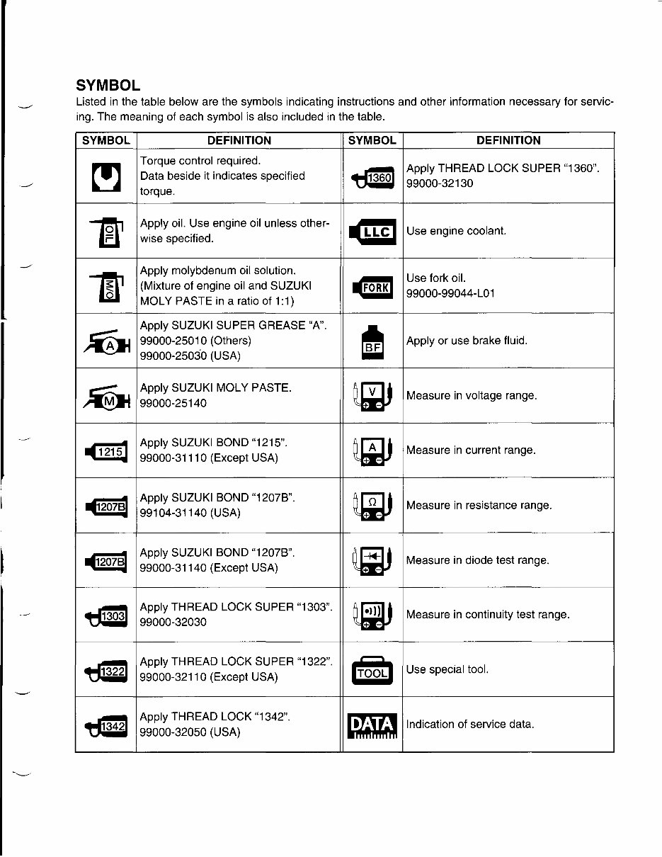
ABBREVIATIONS USED IN THIS MANUAL A ABDC : After Bottom Dead Center AC : Alternating Current ACL : Air Cleaner, Air Cleaner Box API : American Petroleum Institute ATDC : After Top Dead Center ATM Pressure: Atmospheric Pressure : Atmospheric Pressure sensor (APS, AP Sensor) A/F : Air Fuel Mixture E ECM : Engine Control Module Engine Control Unit (ECU) (FI Control Unit) ECT Sensor : Engine Coolant Temperature Sensor (ECTS), Water Temp. Sensor (WTS) EVAP : Evaporative Emission EVAP Canister: Evaporative Emission Canister (Canister) EXC System : Exhaust Control System (EXCS) EXC Valve : Exhaust Control Valve (EXCV) EXCV Actuator: Exhaust Control Valve Actuator (EXCVA) B BBDC BTDC B+ C CKP Sensor CKT CLP Switch CMP Sensor CO CPU D DC DMC DOHC DRL : Before Bottom Dead Center : Before Top Dead Center : Battery Positive Voltage : Crankshaft Position Sensor (CKPS) : Circuit : Clutch Lever Position Switch (Clutch Switch) : Camshaft Position Sensor (CMPS) : Carbon Monoxide : Central Processing Unit : Direct Current : Dealer Mode Coupler : Double Over Head Camshaft : Daytime Running Light F FI FP FPR FP Relay G GEN GND GP Switch H HC I lAP Sensor IAT Sensor IG L LCD LED LH : Fuel Injection, Fuel Injector : Fuel Pump : Fuel Pressure Regulator : Fuel Pump Relay : Generator : Ground : Gear Position Switch : Hydrocarbons : Intake Air Pressure Sensor (lAPS) : Intake Air Temperature Sensor (lATS) : Ignition : Liquid Crystal Display : Light Emitting Diode (Malfunction Indicator Lamp) : Left Hand
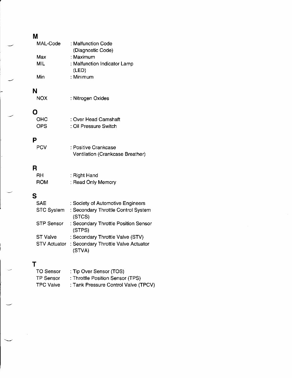
M MAL-Code Max MIL Min N NOX o OHC OPS p PCV R RH ROM S SAE STC System STP Sensor ST Valve STV Actuator T TO Sensor TP Sensor TPC Valve : Malfunction Code (Diagnostic Code) : Maximum : Malfunction Indicator Lamp (LED) : Minimum : Nitrogen Oxides : Over Head Camshaft : Oil Pressure Switch : Positive Crankcase Ventilation (Crankcase Breather) : Right Hand : Read Only Memory : Society of Automotive Engineers : Secondary Throttle Control System (STCS) : Secondary Throttle Position Sensor (STPS) : Secondary Throttle Valve (STV) : Secondary Throttle Valve Actuator (STVA) : Tip Over Sensor (TOS) : Throttle Position Sensor (TPS) : Tank Pressure Control Valve (TPCV)
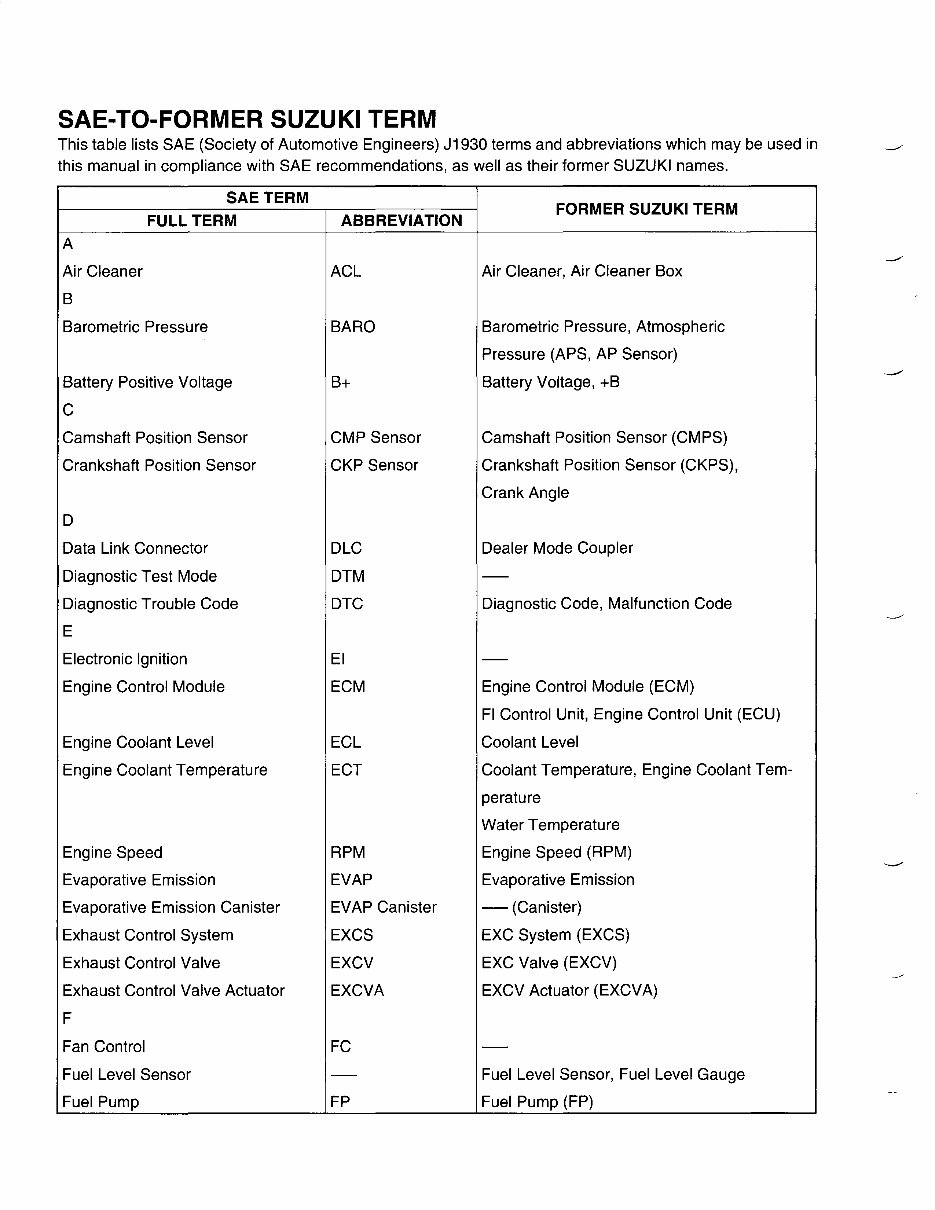
SAE-TO-FORMER SUZUKI TERM This table lists SAE (Society of Automotive Engineers) J1930 terms and abbreviations which may be used in this manual in compliance with SAE recommendations, as well as their former SUZUKI names. SAE TERM FORMER SUZUKI TERM FULL TERM ABBREVIATION A Air Cleaner ACl Air Cleaner, Air Cleaner Box B Barometric Pressure BARO Barometric Pressure, Atmospheric Pressure (APS, AP Sensor) Battery Positive Voltage B+ Battery Voltage, +B C Camshaft Position Sensor CMP Sensor Camshaft Position Sensor (CMPS) Crankshaft Position Sensor CKP Sensor Crankshaft Position Sensor (CKPS), Crank Angle D Data Link Connector DlC Dealer Mode Coupler Diagnostic Test Mode DTM - Diagnostic Trouble Code DTC Diagnostic Code, Malfunction Code E Electronic Ignition EI - Engine Control Module ECM Engine Control Module (ECM) FI Control Unit, Engine Control Unit (ECU) Engine Coolant level ECl Coolant level Engine Coolant Temperature ECT Coolant Temperature, Engine Coolant Tem- perature Water Temperature Engine Speed RPM Engine Speed (RPM) Evaporative Emission EVAP Evaporative Emission Evaporative Emission Canister EVAP Canister - (Canister) Exhaust Control System EXCS EXC System (EXCS) Exhaust Control Valve EXCV EXC Valve (EXCV) Exhaust Control Valve Actuator EXCVA EXCV Actuator (EXCVA) F Fan Control FC - Fuel level Sensor - Fuel level Sensor, Fuel level Gauge Fuel Pump FP Fuel Pump (FP)
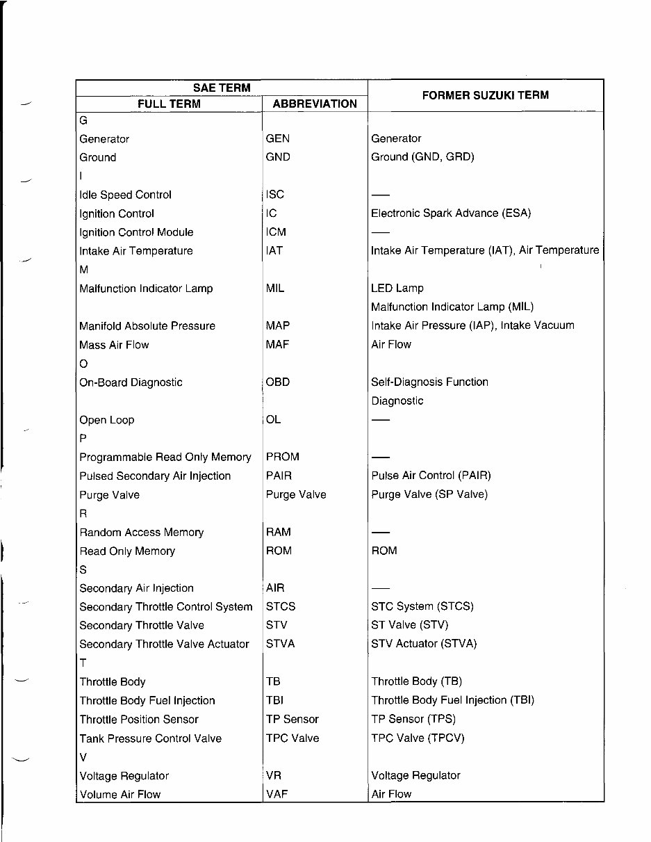
SAE TERM FORMER SUZUKI TERM FULL TERM ABBREVIATION G Generator GEN Generator Ground GND Ground (GND, GRD) I Idle Speed Control ISC - Ignition Control IC Electronic Spark Advance (ESA) Ignition Control Module ICM - Intake Air Temperature IAT Intake Air Temperature (IAT), Air Temperature M I Malfunction Indicator Lamp MIL LED Lamp Malfunction Indicator Lamp (MIL) Manifold Absolute Pressure MAP Intake Air Pressure (lAP), Intake Vacuum Mass Air Flow MAF Air Flow a On-Board Diagnostic OBD Self-Diagnosis Function Diagnostic Open Loop OL - P Programmable Read Only Memory PROM - Pulsed Secondary Air Injection PAIR Pulse Air Control (PAIR) Purge Valve Purge Valve Purge Valve (SP Valve) R Random Access Memory RAM - Read Only Memory ROM ROM S Secondary Air Injection AIR - Secondary Throttle Control System STCS STC System (STCS) Secondary Throttle Valve STV ST Valve (STV) Secondary Throttle Valve Actuator STVA STV Actuator (STVA) T Throttle Body TB Throttle Body (TB) Throttle Body Fuel Injection TBI Throttle Body Fuel Injection (TBI) Throttle Position Sensor TP Sensor TP Sensor (TPS) Tank Pressure Control Valve TPC Valve TPC Valve (TPCV) V Voltage Regulator VR Voltage Regulator Volume Air Flow VAF Air Flow
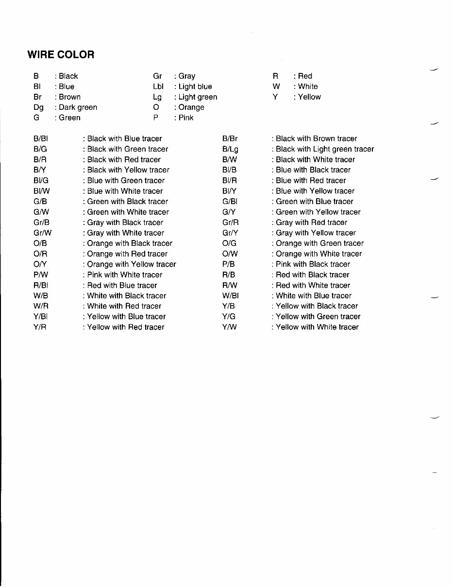
WIRE COLOR B : Black Gr : Gray R : Red BI : Blue Lbl : Light blue W : White Br : Brown Lg : Light green Y : Yellow Dg : Dark green 0 : Orange G : Green P : Pink BIBI BIG BIR BN BI/G BI/W GIB G/W GrlB Gr/W OIB OIR ON P/w RIBI WIB WIR YIBI YIR : Black with Blue tracer : Black with Green tracer : Black with Red tracer : Black with Yellow tracer : Blue with Green tracer : Blue with White tracer : Green with Black tracer : Green with White tracer : Gray with Black tracer : Gray with White tracer : Orange with Black tracer : Orange with Red tracer : Orange with Yellow tracer : Pink with White tracer : Red with Blue tracer : White with Black tracer : White with Red tracer : Yellow with Blue tracer : Yellow with Red tracer BIBr B/Lg B/W BIIB BIIR BIN GIBI GN GrlR GrN OIG O/w PIB RIB R/W WIBI YIB YIG Y/w : Black with Brown tracer : Black with Light green tracer : Black with White tracer : Blue with Black tracer : Blue with Red tracer : Blue with Yellow tracer : Green with Blue tracer : Green with Yellow tracer : Gray with Red tracer : Gray with Yellow tracer : Orange with Green tracer : Orange with White tracer : Pink with Black tracer : Red with Black tracer : Red with White tracer : White with Blue tracer : Yellow with Black tracer : Yellow with Green tracer : Yellow with White tracer
GENERAL INFORMATION 1·1 I GENERALWFORMATION CONTENTS WARNING/CAUTION/NOTE 1- 2 GENERAL PRECAUTIONS.....................................................................• ..... 1- 2 SUZUKI GSX-R1000K3 ('03-MODEL) .......................•.................................. 1- 4 SERIAL NUMBER LOCATION............•......................................................... 1- 4 FUEL, OIL AND ENGINE COOLANT RECOMMENDATlON .........••............. 1- 5 FUEL (FOR USA AND CANADA) ...................................................• ....... 1- 5 FUEL (FOR OTHER COUNTRIES)••................•......................... ........•..•.1- 5 ENGINE OIL (FOR USA) ...........................•...................... ....................... 1- 5 ENGINE OIL (FOR OTHER COUNTRIES) .....................•..•.................... 1- 5 BRAKE FLUiD•...........................•....................• ..................................• .... 1- 5 FRONT FORK OIL ..........................................•....................................... 1- 6 ENGINE COOLANT ..........•...........................•.......................•................. 1- 6 WATER FOR MIXING ....................•..........................•............................. 1- 6 ANTI-FREEZE/ENGINE COOLANT ..........•............................................. 1- 6 LIQUID AMOUNT OF WATER/ENGINE COOLANT .........................•.... 1- 6 BREAK-IN PROCEDURES 1- 7 CYLINDER IDENTIFICATION ....................................................................•.. 1- 7 INFORMATION LABELS...........................................................• ................... 1- 8 SPECIFICATIONS ......................................•..........•.......................•............... 1- 9 DIMENSIONS AND DRY MASS 1- 9 ENGINE ..........................................••........................................•........•..... 1- 9 DRIVE TRAIN ...................•.................••.......................•.........•......•...•...... 1- 9 CHASSiS .................••...................•.•...............•..................•......•.......••.•...1-10 ELECTRICAL .............................................................• .................• .......... 1-10 CAPACiTIES 1-10 COUNTRY AND AREA CODES ....................•................•.............................. 1-11 •
1-2 GENERAL INFORMATION WARNING/CAUTION/NOTE Please read this manual and follow its instructions carefully. To emphasize special information, the symbol and the words WARNING, CAUTION and NOTE have special meanings. Pay special attention to the mes- sages highlighted by these signal words. A WARNING Indicates a potential hazard that could result in death or injury. I CAUTION I Indicates a potential hazard that could result in motorcycle damage. NOTE: Indicates special information to make maintenance easier or instructions clearer. Please note, however, that the warnings and cautions contained in this manual cannot possibly cover all potential hazards relating to the servicing, or lack of servicing, of the motorcycle. In addition to the WARN- INGS and CAUTIONS stated, you must use good judgement and basic mechanical safety principles. If you are unsure about how to perform a particular service operation, ask a more experienced mechanic for advice. GENERAL PRECAUTIONS A WARNING * Proper service and repair procedures are important for the safety of the service mechanic and the safety and reliability of the motorcycle. * When 2 or more persons work together, pay attention to the safety of each other. * When it is necessary to run the engine indoors, make sure that exhaust gas in forced out- doors. * When working with toxic or flammable materials, make sure that the area you work in is well- ventilated and that you follow all of the material manufacturer's instructions. * Never use gasoline as a cleaning solvent. * To avoid getting burned, do not touch the engine, engine oil, radiator and exhaust system until they have cooled. After servicing the fuel, oil, water, exhaust or brake systems, check all lines and fittings related to the system for leaks.
This is the manual for the SUZUKI GSXR 1000 K3 SERVICE MANUAL, providing instant access to a complete guide for repairing and maintaining your vehicle. It is designed to be user-friendly, with proper pictures and illustrations to make your work easier. The manual covers technical features, maintenance, clutch/gearshift linkage, front driving mechanism, electric power steering, lubrication system, lights/meters/switches, ignition system, rear driving mechanism, brake system, general information, cylinder head/valve, alternator/starter clutch, crankcase/transmission, index, cylinder/piston, battery/charging system, wheel/suspension/steering, electric starter, wiring diagrams, troubleshooting, electric shift program, rear wheel/suspension, engine removal/installation, selectable 4WD system, and cylinder head/valve.