00 0 1 2 3 4 5 6 7 8 9 10 11 Precautions............................................................... 00-i Precautions ............................................................ 00-1 General Information ................................................... 0-i General Information ............................................... 0A-1 Maintenance and Lubrication ................................. 0B-1 Service Data........................................................... 0C-1 Engine ......................................................................... 1-i Precautions .............................................................. 1-1 Engine General Information and Diagnosis ........... 1A-1 Emission Control Devices ...................................... 1B-1 Engine Electrical Devices....................................... 1C-1 Engine Mechanical ................................................. 1D-1 Engine Lubrication System .................................... 1E-1 Engine Cooling System.......................................... 1F-1 Fuel System ...........................................................1G-1 Ignition System....................................................... 1H-1 Starting System....................................................... 1I-1 Charging System.....................................................1J-1 Exhaust System ..................................................... 1K-1 Suspension ................................................................. 2-i Precautions .............................................................. 2-1 Suspension General Diagnosis .............................. 2A-1 Front Suspension ................................................... 2B-1 Rear Suspension.................................................... 2C-1 Wheels and Tires ................................................... 2D-1 Driveline / Axle ........................................................... 3-i Precautions .............................................................. 3-1 Drive Chain / Drive Train / Drive Shaft ................... 3A-1 Brake ........................................................................... 4-i Precautions .............................................................. 4-1 Brake Control System and Diagnosis .................... 4A-1 Front Brakes........................................................... 4B-1 Rear Brakes ........................................................... 4C-1 ABS ........................................................................ 4E-1 Transmission / Transaxle ............................................ 5-i Precautions .............................................................. 5-1 Manual Transmission ............................................. 5B-1 Clutch ..................................................................... 5C-1 Steering ....................................................................... 6-i Precautions .............................................................. 6-1 Steering General Diagnosis ................................... 6A-1 Steering / Handlebar .............................................. 6B-1 Body and Accessories............................................... 9-i Precautions .............................................................. 9-1 Wiring Systems ...................................................... 9A-1 Lighting Systems .................................................... 9B-1 Combination Meter / Fuel Meter / Horn .................. 9C-1 Exterior Parts ......................................................... 9D-1 Body Structure ....................................................... 9E-1 TABLE OF CONTENTS Revised 11/07
SUPPLEMENTS GSF1250S/SAK9 ('09-MODEL) 10
Table of Contents 00- i 00 Section 00 CONTENTS Precautions Precautions ............................................... 00-1 Precautions........................................................... 00-1 Warning / Caution / Note..................................... 00-1 General Precautions ........................................... 00-1 Precautions for Electrical Circuit Service ............ 00-2
00-1 Precautions: Precautions Precautions Precautions Warning / Caution / Note B718H20000001 Please read this manual and follow its instructions carefully. To emphasize special information, the symbol and the words WARNING, CAUTION and NOTE have special meanings. Pay special attention to the messages highlighted by these signal words. WARNING ! Indicates a potential hazard that could result in death or injury. CAUTION ! Indicates a potential hazard that could result in motorcycle damage. NOTE Indicates special information to make maintenance easier or instructions clearer. Please note, however, that the warnings and cautions contained in this manual cannot possibly cover all potential hazards relating to the servicing, or lack of servicing, of the motorcycle. In addition to the WARNINGS and CAUTIONS stated, you must use good judgement and basic mechanical safety principles. If you are unsure about how to perform a particular service operation, ask a more experienced mechanic for advice. General Precautions B718H20000002 WARNING ! • Proper service and repair procedures are important for the safety of the service mechanic and the safety and reliability of the motorcycle. • When 2 or more persons work together, pay attention to the safety of each other. • When it is necessary to run the engine indoors, make sure that exhaust gas is forced outdoors. • When working with toxic or flammable materials, make sure that the area you work in is well ventilated and that you follow all of the material manufacturer’s instructions. • Never use gasoline as a cleaning solvent. • To avoid getting burned, do not touch the engine, engine oil, oil cooler and exhaust system until they have cooled. • After servicing the fuel, oil, water, exhaust or brake systems, check all lines and fittings related to the system for leaks. CAUTION ! • If parts replacement is necessary, replace the parts with Suzuki Genuine Parts or their equivalent. • When removing parts that are to be reused, keep them arranged in an orderly manner so that they may be reinstalled in the proper order and orientation. • Be sure to use special tools when instructed. • Make sure that all parts used in reassembly are clean. Lubricate them when specified. • Use the specified lubricant, bond, or sealant. • When removing the battery, disconnect the negative (–) cable first and then the positive (+) cable. • When reconnecting the battery, connect the positive (+) cable first and then the negative (–) cable, and replace the terminal cover on the positive (+) terminal. • When performing service to electrical parts, if the service procedures do not require use of battery power, disconnect the negative (–) cable the battery. • When tightening the cylinder head or case bolts and nuts, tighten the larger sizes first. Always tighten the bolts and nuts diagonally from the inside toward outside and to the specified tightening torque. • Whenever you remove oil seals, gaskets, packing, O-rings, locking washers, self- locking nuts, cotter pins, circlips and certain other parts as specified, be sure to replace them with new ones. Also, before installing these new parts, be sure to remove any left over material from the mating surfaces. • Never reuse a circlip. When installing a new circlip, take care not to expand the end gap larger than required to slip the circlip over the shaft. After installing a circlip, always ensure that it is completely seated in its groove and securely fitted.
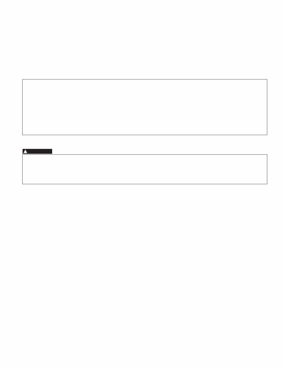
Precautions: 00-2 • Use a torque wrench to tighten fasteners to the specified torque. Wipe off grease and oil if a thread is smeared with them. • After reassembling, check parts for tightness and proper operation. • To protect the environment, do not unlawfully dispose of used motor oil, engine coolant and other fluids: batteries, and tires. • To protect Earth’s natural resources, properly dispose of used motorcycle and parts. Precautions for Electrical Circuit Service B718H20000003 When handling the electrical parts or servicing the FI and ABS systems, observe the following points for the safety of the systems. Electrical Parts Connector / Coupler • When connecting a connector, be sure to push it in until a click is felt. • With a lock type coupler, be sure to release the lock when disconnecting, and push it in fully to engage the lock when connecting. • When disconnecting the coupler, be sure to hold the coupler body and do not pull the lead wires. • Inspect each terminal on the connector/coupler for looseness or bending. • Inspect each terminal for corrosion and contamination. The terminals must be clean and free of any foreign material which could impede proper terminal contact. • Inspect each lead wire circuit for poor connection by shaking it by hand lightly. If any abnormal condition is found, repair or replace. • When taking measurements at electrical connectors using a tester probe, be sure to insert the probe from the wire harness side (rear) of the connector/coupler. • When connecting meter probe from the terminal side of the coupler (where connection from harness side not being possible), use extra care not to force and cause the male terminal to bend or the female terminal to open. Connect the probe as shown to avoid opening of female terminal. Never push in the probe where male terminal is supposed to fit. I310G1000001-01 1. Coupler 2. Probe I310G1000002-01 I310G1000003-01 2 1 I649G1000013-01
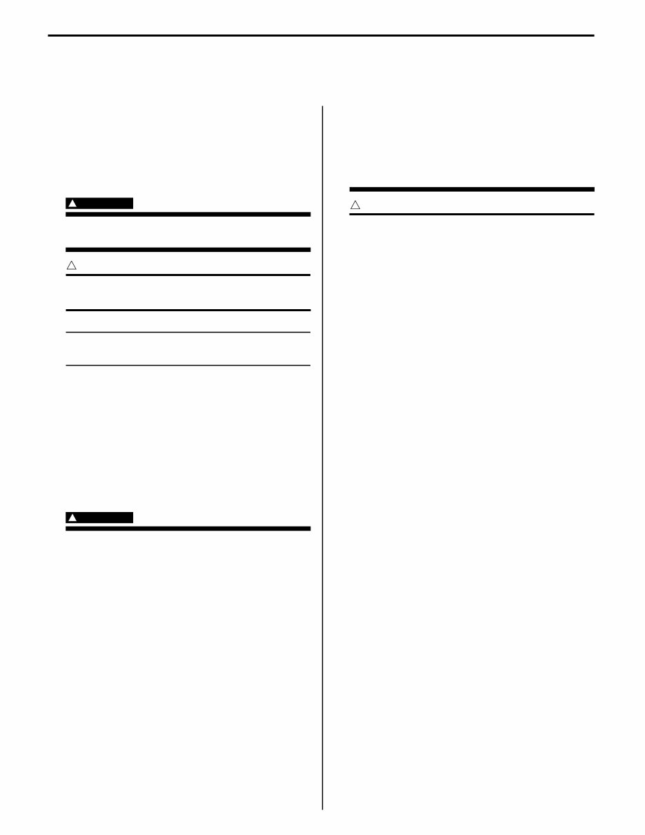
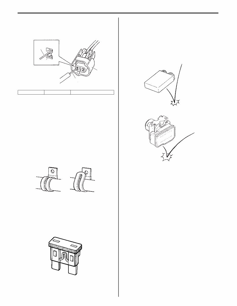
00-3 Precautions: • Check the male connector for bend and female connector for excessive opening. Also check the coupler for locking (looseness), corrosion, dust, etc. Clamp • Clamp the wire harness at such positions as indicated in “Wiring Harness Routing Diagram in Section 9A (Page 9A-7)”. • Bend the clamp properly so that the wire harness is clamped securely. • In clamping the wire harness, use care not to allow it to hang down. • Do not use wire or any other substitute for the band type clamp. Fuse • When a fuse is blown, always investigate the cause to correct it and then replace the fuse. • Do not use a fuse of different capacity. • Do not use wire or any other substitute for the fuse. Switch Never apply grease material to switch contact points to prevent damage. ECM / ABS control unit / HU / Various sensors • Since each component is a high-precision part, great care should be taken not to apply any severe impacts during removal and installation. 3. Coupler 4. Probe “A”: Where male terminal fits 3 4 4 “A” I649G1000030-01 CORRECT INCORRECT I718H1000001-02 I649G1000001-01 I310G1000007-01 I649G1000003-01
This is a comprehensive service repair manual for the SUZUKI GSF1250 / GSF1250S / GSF1250A/ GSF1250SA Bandit motorcycle, covering production model years 2007, 2008, and 2009. It is a complete manual similar to factory shop manuals or CDROM manuals used in repair shops, providing information for simple to complicated repairs.
The manual includes the following sections:
Precautions
General Information
Maintenance and Lubrication
Service Data
Engine
General Information and Diagnosis
Emission Control Devices
Engine Electrical Devices
Engine Mechanical
Engine Lubrication System
Engine Cooling System
Fuel System
Ignition System
Starting System
Charging System
Exhaust System
Suspension
Suspension General Diagnosis
Front Suspension
Rear Suspension
Wheels and Tires
Driveline / Axle
Drive Chain / Drive Train / Drive Shaft
Brake
Brake Control System and Diagnosis
Front Brakes
Rear Brakes
ABS
Transmission / Transaxle
Manual Transmission
Clutch
Steering
Steering General Diagnosis
Steering / Handlebar
Body and Accessories
Wiring Systems
Lighting Systems
Combination Meter / Fuel Meter / Horn
Exterior Parts
Body Structure
Model Specification: SUZUKI GSF1250 / GSF1250S / GSF1250A/ GSF1250SA Bandit
Model Year: 2007-2009
Language: English
Format: PDF
Requirements: Adobe Reader & Win
Zoom In/Out: Yes
Printable: Yes
Compatible: All Versions of Windows & Mac
This professional quality, highly detailed service repair workshop manual provides step-by-step instructions, exploded pictures, and diagrams to facilitate correct and efficient completion of all repair procedures. It covers the entire vehicle and is the same type of manual used by professional mechanics to service or repair the motorcycle.
All manuals are compatible with Windows Vista 32 and 64, XP, ME, 98, NT, 2000, and Mac. They are printable, allowing for easy access in the garage or workshop, and enable cost-saving through DIY repairs.
Instant access is available upon receipt of payment, with no shipping costs or waiting for a CD to arrive. The manual includes tons of pictures and diagrams for easy reference.