

2010 Suzuki Burgman (AN400) OEM Service & Repair Manual
What's Included?
Fast Download Speeds
Online & Offline Access
Access PDF Contents & Bookmarks
Full Search Facility
Print one or all pages of your manual
99500-34100-01E
AN400
FOREWORD
This manual contains an introductory description on the SUZUKI AN400 and procedures for its inspection/service
and overhaul of its main components.
Other information considered as generally known is not included.
Read the GENERAL INFORMATION section to familiarize yourself with the motorcycle and its maintenance. Use
this section as well as other sections to use as a guide for proper inspection and service.
This manual will help you know the motorcycle better so that you can assure your customers of fast and reliable
service.
© COPYRIGHT SUZUKI MOTOR CORPORATION 2012
* This manual has been prepared on the basis of the latest specifications at the time of publication. If modifi-
cations have been made since then, differences may exist between the content of this manual and the
actual motorcycle.
* Illustrations in this manual are used to show the basic principles of operation and work procedures. They
may not represent the actual motorcycle exactly in detail.
* This manual is written for persons who have enough knowledge, skills and tools, including special tools, for
servicing SUZUKI motorcycles. If you do not have the proper knowledge and tools, ask your authorized
SUZUKI motorcycle dealer to help you.
WARNING !
Inexperienced mechanics or mechanics without the proper tools and equipment may not be able to
properly perform the services described in this manual.
Improper repair may result in injury to the mechanic and may render the motorcycle unsafe for the
rider and passenger.

00
0
1
2
3
4
5
6
9
Precautions............................................................... 00-i
Precautions ............................................................ 00-1
General Information ................................................... 0-i
General Information ............................................... 0A-1
Maintenance and Lubrication ................................. 0B-1
Service Data........................................................... 0C-1
Engine ......................................................................... 1-i
Precautions .............................................................. 1-1
Engine General Information and Diagnosis ........... 1A-1
Emission Control Devices ...................................... 1B-1
Engine Electrical Devices....................................... 1C-1
Engine Mechanical ................................................. 1D-1
Engine Lubrication System .................................... 1E-1
Engine Cooling System.......................................... 1F-1
Fuel System ...........................................................1G-1
Ignition System....................................................... 1H-1
Starting System....................................................... 1I-1
Charging System.....................................................1J-1
Exhaust System ..................................................... 1K-1
Suspension ................................................................. 2-i
Precautions .............................................................. 2-1
Suspension General Diagnosis .............................. 2A-1
Front Suspension ................................................... 2B-1
Rear Suspension.................................................... 2C-1
Wheels and Tires ................................................... 2D-1
Driveline / Axle ........................................................... 3-i
Precautions .............................................................. 3-1
Drive Chain / Drive Train / Drive Shaft ................... 3A-1
Brake ........................................................................... 4-i
Precautions .............................................................. 4-1
Brake Control System and Diagnosis .................... 4A-1
Front Brakes........................................................... 4B-1
Rear Brakes ........................................................... 4C-1
Parking Brake......................................................... 4D-1
Tranmission / Transaxle ............................................ 5-i
Precautions .............................................................. 5-1
Automatic Transmission ......................................... 5A-1
Steering ....................................................................... 6-i
Precautions .............................................................. 6-1
Steering General Diagnosis ................................... 6A-1
Steering / Handlebar .............................................. 6B-1
Body and Accessories............................................... 9-i
Precautions .............................................................. 9-1
Wiring Systems ...................................................... 9A-1
Lighting Systems .................................................... 9B-1
Combination Meter / Fuel Meter / Horn .................. 9C-1
Exterior Parts ......................................................... 9D-1
Body Structure ....................................................... 9E-1
TABLE OF CONTENTS


Table of Contents 00- i
00
Section 00
CONTENTS
Precautions
Precautions ............................................... 00-1
Precautions........................................................... 00-1
Warning / Caution / Note..................................... 00-1
General Precautions ........................................... 00-1
Precautions for Electrical Circuit Service ............ 00-2
00-1 Precautions:
Precautions
Precautions
Warning / Caution / Note
B705H10000001
Please read this manual and follow its instructions
carefully. To emphasize special information, the symbol
and the words WARNING, CAUTION and NOTE have
special meanings. Pay special attention to the messages
highlighted by these signal words.
WARNING !
Indicates a potential hazard that could result
in death or injury.
CAUTION !
Indicates a potential hazard that could result
in motorcycle damage.
NOTE
Indicates special information to make
maintenance easier or instructions clearer.
Please note, however, that the warnings and cautions
contained in this manual cannot possibly cover all
potential hazards relating to the servicing, or lack of
servicing, of the motorcycle. In addition to the
WARNINGS and CAUTIONS stated, you must use good
judgement and basic mechanical safety principles. If you
are unsure about how to perform a particular service
operation, ask a more experienced mechanic for advice.
General Precautions
B705H10000002
WARNING !
• Proper service and repair procedures are
important for the safety of the service
mechanic and the safety and reliability of
the motorcycle.
• When 2 or more persons work together,
pay attention to the safety of each other.
• When it is necessary to run the engine
indoors, make sure that exhaust gas is
forced outdoors.
• When working with toxic or flammable
materials, make sure that the area you
work in is well-ventilated and that you
follow all of the material manufacturer’s
instructions.
• Never use gasoline as a cleaning solvent.
• To avoid getting burned, do not touch the
engine, engine oil, radiator and exhaust
system until they have cooled.
• After servicing the fuel, oil, water, exhaust
or brake systems, check all lines and
fittings related to the system for leaks.
Precautions: 00-2
CAUTION !
• If parts replacement is necessary, replace
the parts with Suzuki Genuine Parts or
their equivalent.
• When removing parts that are to be reused,
keep them arranged in an orderly manner
so that they may be reinstalled in the
proper order and orientation.
• Be sure to use special tools when
instructed.
• Make sure that all parts used in
reassembly are clean. Lubricate them
when specified.
• Use the specified lubricant, bond or
sealant.
• When removing the battery, disconnect the
(–) cable first and then the (+) cable.
• When reconnecting the battery, connect
the (+) cable first and then the (–) cable,
and replace the terminal cover on the (+)
terminal.
• When performing service to electrical
parts, if the service procedures do not
require use of battery power, disconnect
the (–) cable from the battery.
• When tightening the cylinder head or case
bolts and nuts, tighten the larger sizes
first. Always tighten the bolts and nuts
diagonally from the inside toward outside
and to the specified tightening torque.
• Whenever you remove oil seals, gaskets,
packing, O-rings, locking washers, self-
locking nuts, cotter pins, circlips and
certain other parts as specified, be sure to
replace them with new ones. Also, before
installing these new parts, be sure to
remove any left over material from the
mating surfaces.
• Never reuse a circlip. When installing a
new circlip, take care not to expand the
end gap larger than required to slip the
circlip over the shaft. After installing a
circlip, always ensure that it is completely
seated in its groove and securely fitted.
• Use a torque wrench to tighten bolts to the
specified torque. Wipe off grease and oil if
a thread is smeared with them.
• After reassembling, check parts for
tightness and proper operation.
• To protect the environment, do not
unlawfully dispose of used motor oil,
engine coolant and other fluids: batteries
and tires.
• To protect Earth’s natural resources,
properly dispose of used motorcycle and
parts.
Precautions for Electrical Circuit Service
B705H10000003
When handling the component parts or servicing the FI
system, observe the following points for the safety of the
system.
Electrical Parts
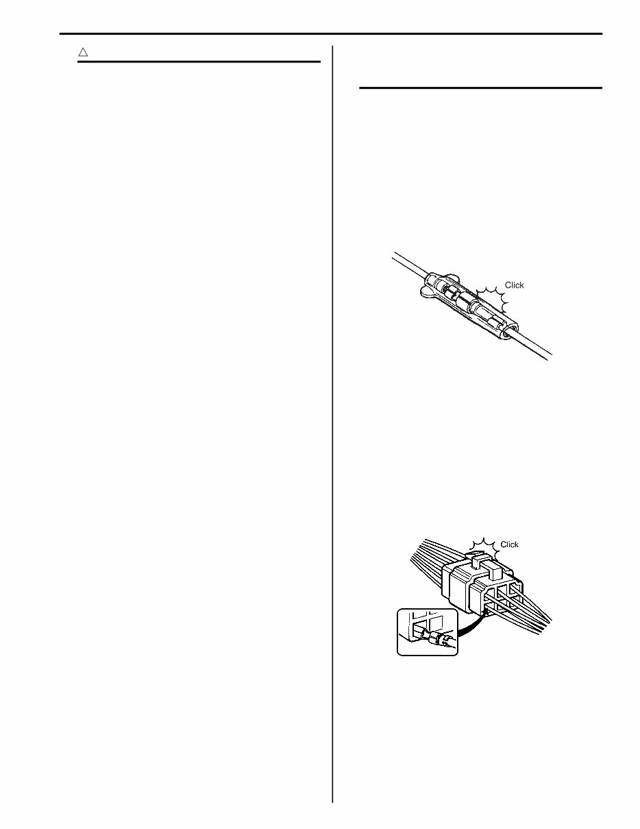
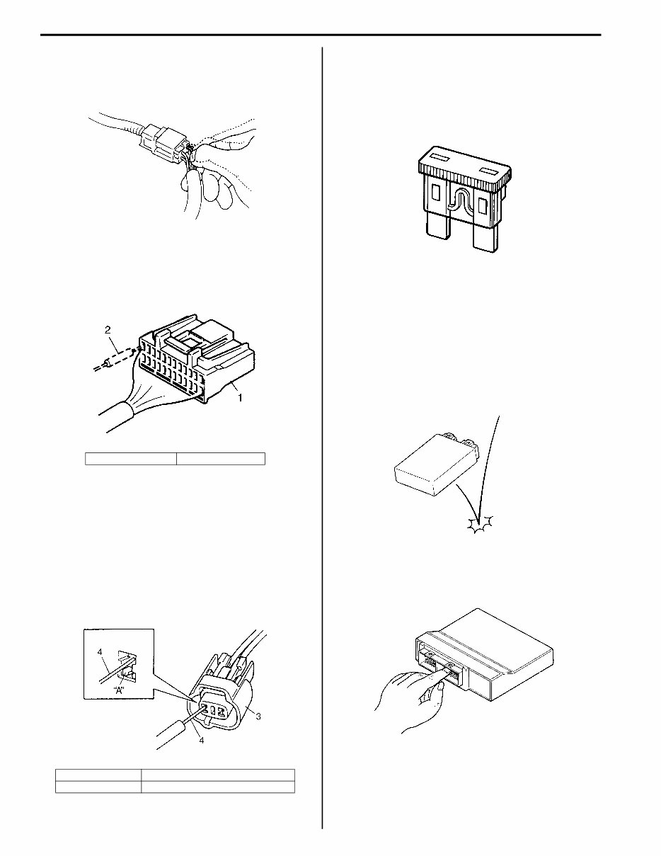
Connector / Coupler
• When connecting a connector, be sure to push it in
until a click is felt.
• With a lock type coupler, be sure to release the lock
when disconnecting, and push in fully to engage the
lock when connecting.
• When disconnecting the coupler, be sure to hold the
coupler body and do not pull the lead wires.
• Inspect each terminal on the connector/coupler for
looseness or bending.
• Inspect each terminal for corrosion and
contamination. The terminals must be clean and free
of any foreign material which could impede proper
terminal contact.
I705H1000001-01
I310G1000002-01
00-3 Precautions:
• Inspect each lead wire circuit for poor connection by
shaking it by hand lightly. If any abnormal condition is
found, repair or replace.
• When taking measurements at electrical connectors
using a tester probe, be sure to insert the probe from
the wire harness side (backside) of the connector/
coupler.
• When connecting meter probe from the terminal side
of the coupler (where connection from harness side
not being possible), use extra care not to force and
cause the male terminal to bend or the female
terminal to open. Connect the probe as shown to
avoid opening of female terminal. Never push in the
probe where male terminal is supposed to fit.
• Check the male connector for bend and female
connector for excessive opening. Also check the
coupler for locking (looseness), corrosion, dust, etc.
Fuse
• When a fuse blows, always investigate the cause to
correct it and then replace the fuse.
• Do not use a fuse of a different capacity.
• Do not use wire or any other substitute for the fuse.
Switch
Never apply grease material to switch contact points to
prevent damage.
ECM / Various Sensors
• Since each component is a high-precision part, great
care should be taken not to apply any sharp impacts
during removal and installation.
• Be careful not to touch the electrical terminals of the
ECM. The static electricity from your body may
damage this part.
1. Coupler 2. Probe
3. Coupler “A”: Where male terminal fits
4. Probe
I310G1000003-01
I705H1000002-01
I705H1000003-01
I649G1000001-01
I310G1000007-01
I310G1000008-01
Precautions: 00-4
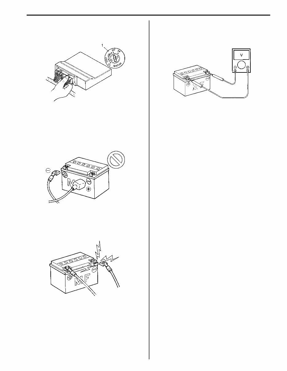
• When disconnecting and connecting the ECM
couplers, make sure to turn OFF the ignition switch
(1), or electronic parts may get damaged.
Battery
• Battery connection in reverse polarity is strictly
prohibited. Such a wrong connection will damage the
components of the FI system instantly when reverse
power is applied.
• Removing any battery terminal of a running engine is
strictly prohibited. The moment such removal is made,
damaging counter electromotive force will be applied
to the ECM which may result in serious damage.
• Before measuring voltage at each terminal, check to
make sure that battery voltage is 11 V or higher.
Terminal voltage check with a low battery voltage will
lead to erroneous diagnosis.
• Never connect any tester (voltmeter, ohmmeter, or
whatever) to the ECM when its coupler is
disconnected. Otherwise, damage to ECM may result.
• Never connect an ohmmeter to the ECM with its
coupler connected. If attempted, damage to ECM or
sensors may result.
• Be sure to use a specified voltmeter/ohmmeter.
Otherwise, accurate measurements may not be
obtained and personal injury may result.
Electrical Circuit Inspection Procedures
While there are various methods for electrical circuit
inspection, described here is a general method to check
for open and short circuit using an ohmmeter and a
voltmeter.
Open circuit check
Possible causes for the open circuits are as follows. As
the cause can exist in the connector/coupler or terminal,
they need to be checked carefully.
• Loose connection of connector/coupler
• Poor contact of terminal (due to dirt, corrosion or rust,
poor contact tension, entry of foreign object, etc.)
• Wire harness being open
• Poor terminal-to-wire connection
I705H1000004-03
I310G1000010-01
I310G1000011-01
I310G1000012-01
00-5 Precautions:
When checking system circuits including an electronic
control unit such as ECM, etc., it is important to perform
careful check, starting with items which are easier to
check.
1) Disconnect the (–) cable from the battery.
2) Check each connector/coupler at both ends of the
circuit being checked for loose connection. Also
check for condition of the coupler lock if equipped.
3) Using a test male terminal, check the female
terminals of the circuit being checked for contact
tension.
Check each terminal visually for poor contact
(possibly caused by dirt, corrosion, rust, entry of
foreign object, etc.). At the same time, check to
make sure that each terminal is fully inserted in the
coupler and locked.
If contact tension is not enough, rectify the contact to
increase tension or replace. The terminals must be
clean and free of any foreign material which could
impede proper terminal contact.
4) Using continuity inspect or voltage check procedures
as described below, inspect the wire harness
terminals for open circuit and poor connection.
Locate abnormality, if any.
Continuity check
1) Measure resistance across coupler “B” (between “A”
and “C” in figure).
If no continuity is indicated (infinity or over limit), the
circuit is open between terminals “A” and “C”.
2) Disconnect the coupler “B” and measure resistance
between couplers “A” and “B-1”.
If no continuity is indicated, the circuit is open
between couplers “A” and “B-1”. If continuity is
indicated, there is an open circuit between couplers
“B-2” and “C” or an abnormality in coupler “B-2” or
coupler “C”.
1. Sensor “A”: Check for loose connection.
“B”: Check contact tension by inserting and removing.
“C”: Check each terminal for bend and proper alignment.
ECM
“A”
“A”
1
I705H1000005-02
“C”
“B”
I649G1000027-01
”D”: Looseness of crimping
“E”: Open
“F”: Thin wire (A few strands left)
“D”
“E”
“F”
I649G1000028-01
ECM
“A”
“B”
“C”
I705H1000006-02
ECM
“A”
“B”
“C”
“B-2”
“B-1”
I705H1000010-02
You're Reading a Preview
What's Included?
Fast Download Speeds
Online & Offline Access
Access PDF Contents & Bookmarks
Full Search Facility
Print one or all pages of your manual
$39.99
Viewed 95 Times Today


Secure transaction
What's Included?
Fast Download Speeds
Online & Offline Access
Access PDF Contents & Bookmarks
Full Search Facility
Print one or all pages of your manual
$39.99
- Get the complete guide for fixing issues with your 2010 Suzuki Burgman (AN400) scooter with this comprehensive repair manual.
- Whether you're a professional mechanic or a DIY enthusiast, this manual includes all the troubleshooting and replacement procedures recommended by the manufacturer.
- It features step-by-step instructions, clear images, and exploded-view illustrations to assist you in maintaining and repairing your scooter.
- Regular maintenance is essential for the durability of your scooter, and this manual provides the manufacturer's recommended troubleshooting charts and replacement procedures.
- By following the manual, you can save on repairs, enhance your scooter's reliability, and reduce the frequency of visits to the repair shop.
- Conveniently search, screenshot, and bookmark information without the hassle of flipping through numerous pages, making it more practical than a traditional bound manual.
- The manual is available in .pdf format and can be printed for physical reference.
- It is compatible with various electronic devices, including PC, Mac computers, Android, and Apple smartphones and tablets, and requires Adobe Reader (free) for access.


