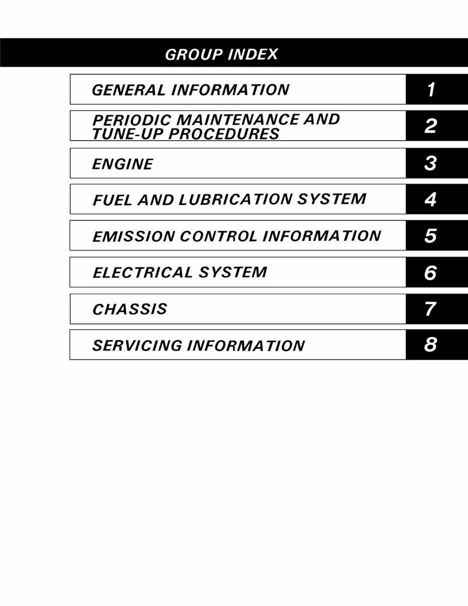
GROUP INDEX GENERAL INFORMATION PERIODIC MAINTENANCE AND ENGINE FUEL AND LUBRICATION SYSTEM EMISSION CONTROL INFORMATION ELECTRICAL SYSTEM CHASSIS SERVICING INFORMATION
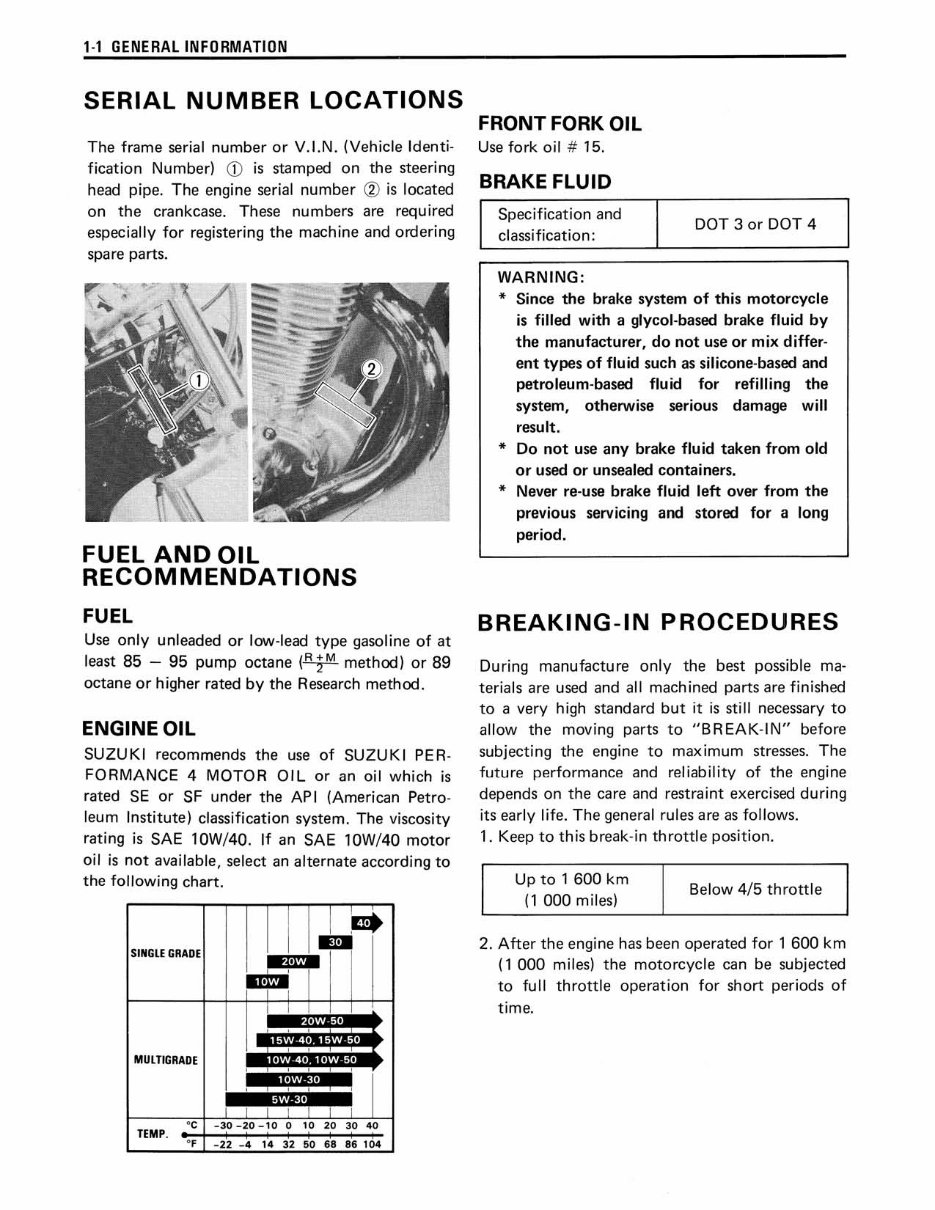
1-1 GENERAL INFORMATI ON SERIAL NUMBER LOCATIONS The frame serial number or V.I.N. (Vehicle Identi- fication Number) CD is stamped on the steering head pipe. The engine serial number ® is located on the crankcase. These numbers are required especially for registering the machine and orderi ng spare parts. FUEL AND OIL RECOMMENDATIONS FUEL Use only unleaded or low-l ead type gaso li ne of at l east 85 - 95 pump octane (~method) or 89 octane or higher rated by the Research method. ENGINE OIL SU Z UK I recommends the use of SUZUKI PER- FORMA NCE 4 MOTOR O IL or an oi l which is rat ed SE or SF under the AP I (Ameri can Petro- leum Institute) classification system. The viscosity rati ng is SAE 10W/40. If an SAE 10W/40 moto r oil is not available, select an alternate according to the following cha rt. SIN G LE G RADE MULTIGRADE TEMP. . . l I • .. . .. 5W·30 FRONT FORK OIL Use fork oil # 15. BRAKE FLUID Specification and cl ass ification: WARNING : DOT 3 or DOT 4 * Since th e brake system of thi s mot orcycle is f ill ed with a glycol-based brake fluid by the ma nufacturer, do not use or mix differ- ent types of fluid such as silicone-based and petroleum-based fluid for refilling the system, otherwise serious da mage w ill result. * Do not use any brake fluid taken from old or used or unsealed containers. * Never re-use brake flu id left over from the previous servicing and stored for a long period. BREAKING-IN PROCEDURES During manufacture only the best possible ma- terials are used and all mach ined parts are f inished to a very high standard but it is sti ll necessary to allow the moving parts to "B REAK-1 N" before subjecting the engine to maximum stresses. T he future perf ormance and re l iability of the engine depends on the care and restraint exercised duri ng its early li fe. The general rules are as follows. 1. Keep to this break-in throttle position. Up to 1 600 km (1 000 miles) Below 4/5 thrott le 2. After the engine has been operated for 1 600 km ( 1 000 miles) the motorcycle can be subjected to full th r ottle operation for short periods of time .
GENERAL INFORMATION 1-2 SPECIAL MATERIALS The materials listed below are needed for maintenance work on the LS650, and should be kept on hand for ready use. They supplement such standard mate ri als as cleaning fluids, lubricants, emery cloth and the like. How to use them and where to use them are described in the text of th is manual. Material SUZUKI SUPER GREASE "A" 99000-25030 SUZUKI S'ILICONE GREASE 99000-251 00 SUZUKI MOLY PASTE 99000-25140 SUZUKI BOND No. 1207B 99104-31140 THREAD LOCK SUPER "1303" 99000-32030 Part Page • Clutch pushrod 3·38 • Oil seals 3-45 3-49 • Throttle grip • Brake pedal shaft • Gearshift lever and shaft • Speedometer cable and dust seal • Starter motor housing end 6-11 • Caliper axle 7-8 • Valve stems 3-28 • De-comp. camshaft 3-37 • Countershaft and drive- 3-41 shaft • Piston pin • Camshaft journals • Rocker arm shafts • De-comp. shaft • Mating surfaces of left and right halves of crankcase • Generator lead wire grommet 3·52 3-55 3-47 • Oil pump screw 3·37 • Starter clutch Allen bolt 3-37 • Crankcase bearing retainer 3·44 screws • Gearshift arm stopper • Generator rotor bolt • Cam sprocket bolts 3-49 3-50 3-54 Part Page • Wheel bearings 7·4, 28 • Steering stem bearings 7-21 • Pulley drum bearing 7-28 • Brake cam and pin 7-28 • Swingarm dust seals, 7-31 spacers and bearings
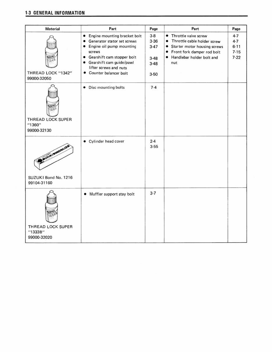
1 -3 GEN E RAL INFORMATIO N Material THREAD LOCK "1342" 9900(}32050 THREAD LOCK SUPER "1360" 99000-32130 SUZUKI Bond No. 1216 99104-31160 THREAD LOCK SUPER "13338" 99000-32020 Part • Engine mounting bracket bolt • Generator stator set screws • Engine oil pump mounting screws • Gearshift cam stopper bolt • Gearshift cam guide/pawl lif ter screws and nuts • Counter ba lancer bolt • Disc mounting bolts • Cylinder head cover Page 3-8 3· 36 3-47 3-48 3·48 3-50 7·4 2-4 3-55 • Muffler support stay bolt 3·7 P art Page • Throttle valve screw 4-7 • Throttle cable holder screw 4·7 • Starter motor housing screws 6-11 • Front fork damper rod bolt 7-15 • Handlebar holder bolt and 7-22 nut
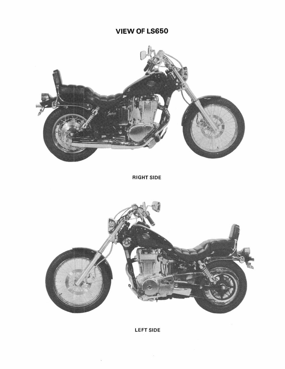
This Service Repair Manual is a comprehensive guide for maintaining and repairing the 2005-2009 Suzuki LS650 S40. It includes high-quality diagrams and detailed instructions covering everything from the front bumper to the rear. Whether you're a professional mechanic or a DIY enthusiast, this manual is a valuable resource.
File Format: PDF
Compatibility: All Versions of Windows & Mac
Language: English
Requirements: Adobe Reader
The manual covers the following models:
2005 Suzuki LS650K5 Boulevard S40
2006 Suzuki LS650K6 Boulevard S40
2007 Suzuki LS650K7 Boulevard S40
2008 Suzuki LS650K8 Boulevard S40
2009 Suzuki LS650K9 Boulevard S40
It includes detailed information on:
General maintenance
Periodic tune-up procedures
Engine maintenance
Fuel and lubrication system
Emission control
Electrical system
Chassis maintenance
Servicing information
All pages are printable, allowing you to easily reference the manual in your garage or workshop. By following the step-by-step instructions, you can save money by performing your own repairs. With instant access, there are no shipping costs or waiting for a CD to arrive. Upon payment completion through our secure processor, you will receive the manual immediately. We accept all major credit/debit cards and PayPal.