

PEUGEOT ELYSTAR Scooter Full Service & Repair Manual
What's Included?
Fast Download Speeds
Online & Offline Access
Access PDF Contents & Bookmarks
Full Search Facility
Print one or all pages of your manual
WORKSHOP
MANUAL
SALES DIVISION
NETWORK TECHNICAL TRAINING
Downloaded from www.Manualslib.com manuals search engine

CONTENTS
Page : 2
Reproduction or translation, even partial, are forbidden without the written consent of Peugeot Motocycles
CHARACTERISTICS......................................................................................................................... 3
PRESENTATION OF THE 4 STROKE INJECTION SYSTEM (EFI) ........................................ 4
Synoptics ................................................................................................................................................. 4
DIAGNOSTIC TOOL ......................................................................................................................... 5
Presentation ............................................................................................................................................. 5
Connection of the diagnostic tool ............................................................................................................ 6
SPECIAL IMPORTANT POINTS .................................................................................................... 7
Fuel system.............................................................................................................................................. 7
TIGHTENING TORQUES ................................................................................................................. 8
50 cc Engine ............................................................................................................................................ 8
125-150 cc Engine ................................................................................................................................... 8
SPECIAL TOOLS ............................................................................................................................... 9
INSTRUMENT PANEL .................................................................................................................... 10
Warning lights description and meanings ............................................................................................. 10
Changing the speedo units ..................................................................................................................... 11
Service function..................................................................................................................................... 11
TRANSPONDER IMMOBILISER.................................................................................................. 12
System programming ............................................................................................................................ 12
Reminder of the key memory procedure ............................................................................................... 12
Key memory check................................................................................................................................ 12
Diagnostic LED readings ...................................................................................................................... 12
Additional information .......................................................................................................................... 13
Troubleshooting chart............................................................................................................................ 14
Ignition principle schematic .................................................................................................................. 15
SPECIAL FEATURES OF THE 2
nd
GENERATION SYNCHRO BRAKING CONCEPT ...... 16
WORKING ON 4-STROKE INJECTION SYSTEMS .................................................................. 17
To remove the fuel pump ...................................................................................................................... 17
To remove the air injector ..................................................................................................................... 20
To remove the throttle housing and idle valve ...................................................................................... 21
WORKING ON THE ABS/PBS SYSTEM...................................................................................... 22
ABS/PBS diagnostic.............................................................................................................................. 22
Troubleshooting chart............................................................................................................................ 22
Incidents which cannot be detected by the ECU ................................................................................... 25
ABS/PBS principle diagram.................................................................................................................. 27
Parameter reading .................................................................................................................................. 28
To remove the control unit .................................................................................................................... 29
To refit the control unit ......................................................................................................................... 32
ABS/PBS SYSTEM BLEED METHOD .......................................................................................... 33
Bleeding the front and rear circuits after changing the control unit ...................................................... 33
Bleeding the circuit after removing a front or rear caliper, a front or rear lower hydraulic hose ......... 37
Bleeding the circuit after removing the front master cylinder or the upper front hydraulic hose (right
side) ....................................................................................................................................................... 39
Bleeding the circuit after removing the rear master cylinder or the upper front hydraulic hose (left side
integral braking) .................................................................................................................................... 41
Bleeding the power braking circuit ....................................................................................................... 43
HAZARD WARNING LIGHTS....................................................................................................... 45
Functioning principle diagram .............................................................................................................. 45
Operation ............................................................................................................................................... 46
LOCATION OF COMPONENTS.................................................................................................... 47
Elystar 50 cc .......................................................................................................................................... 47
Elystar 125-150 cc ................................................................................................................................. 48
Downloaded from www.Manualslib.com manuals search engine
CHARACTERISTICS
Page : 3
Reproduction or translation, even partial, are forbidden without the written consent of Peugeot Motocycles
CHARACTERISTICS
FC5 Engine
50 cc
FD3 Engine
125 cc
FD4 Engine
150 cc
Type
Air-cooled, single-cylinder
2-stroke injection
Single-cylinder 4-stroke coolant cooled
Bore x stroke 40.3 x 39.1 57 x 48.9 57 x 58.9
Cubic capacity 49.1 cc 124.8 cc 150.3 cc
Max. power
output
3.4 kW at 6900 rpm 9 kW at 8700 rpm 10.5 kW at 8200 rpm
Maximum torque 4.7 Nm at 6800 rpm 10.5 Nm at 7500 rpm 12.5 Nm at 6500 rpm
Gross
compression ratio
11,4
Timing Chain driven overhead camshaft, 2-valve
Engine oil
capacity
1.25 L.
Relay box
capacity
0.12 L.
Injection system
TSDI
Two Stroke Direct
Injection
EFI
Electronic Fuel Injection
Ignition /
Carburettor
Synerject ECU Synerject ECU Synerject ECU
Petrol injector Siemens green 37.028 Siemens black 8884
Air injector Synerject blue 37.073
Fuel pressure
regulator
Synerject Synerject
Petrol pump Synerject Synerject
Throttle unit Bing 235 011 Bing 7229 104
Temperature
sensor
Synerject Synerject
Lubrication Trochoidal pump with relief valve
Lubrication
Oil pump
Mikuni ESOP-03
Spark plug NGK CPR8E NGK CR7E
Magneto flywheel Mitsuba 180W Mitsuba 235 W
Starter motor Mitsuba 250 W Mitsuba 440 W
Downloaded from www.Manualslib.com manuals search engine
PRESENTATION OF THE 4 STROKE INJECTION SYSTEM (EFI)
Page : 4
Reproduction or translation, even partial, are forbidden without the written consent of Peugeot Motocycles
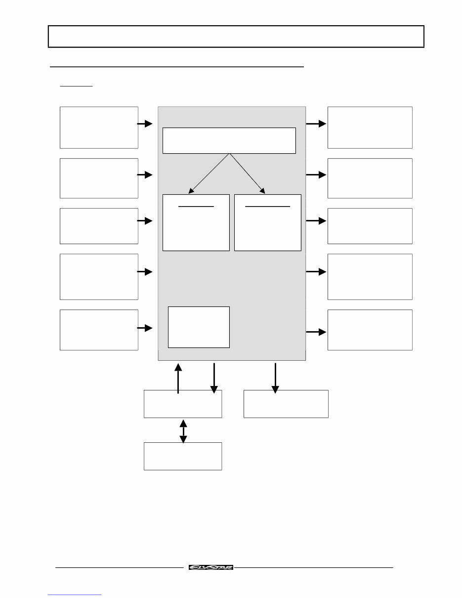
PRESENTATION OF THE 4 STROKE INJECTION SYSTEM (EFI)
Synoptics
Throttle unit Petrol injector
Engine position and
speed sensor
Idle control valve
Engine
temperature sensor
Ignition coil
Battery voltage Fuel pump
Inlet air pressure
and temperature
sensor.
Engine temperature
gauge
Diagnostic plug Diagnostic lamp
Immobiliser
module
INJECTION / IGNITION
ECU
Software:
Manages
system
functioning
Calibration:
Values specific
to machine
(mapping)
ECU locking
code
Downloaded from www.Manualslib.com manuals search engine
DIAGNOSTIC TOOL
Page : 5
Reproduction or translation, even partial, are forbidden without the written consent of Peugeot Motocycles
DIAGNOSTIC TOOL
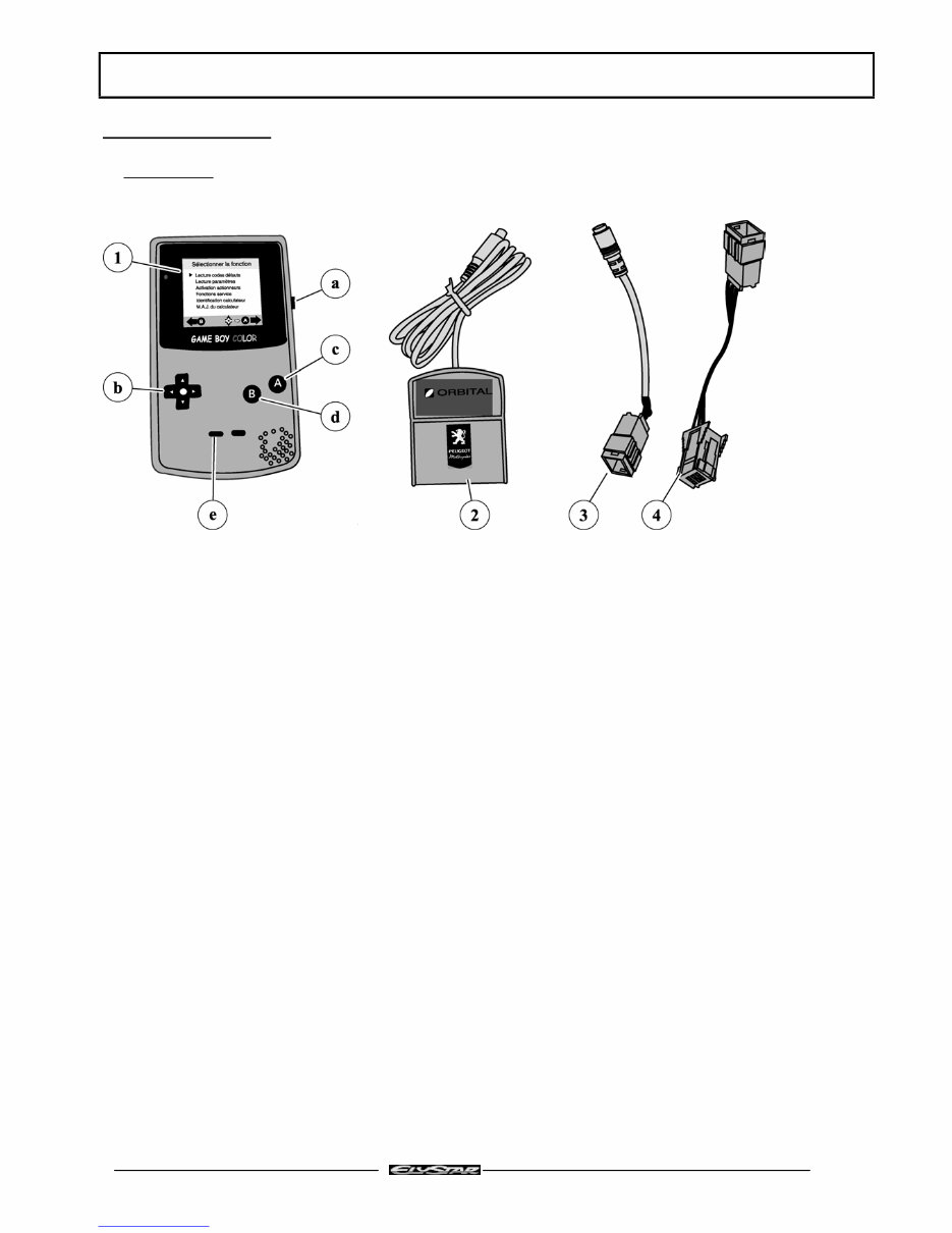
Presentation
1 - A screen, a Nintendo © Game Boy ™ Color console
a - on/off button
b - arrows: select key
c - button A: confirm button
d - button B: return button
e - select button: for help
2 - Cartridge, containing the software for dialog between the machine and the screen
3 - Interface cable between the machine and the tool for diagnostic of the 4-stroke injection system (EFI)
4 - Interface cable between the machine and interface cable (3) for diagnostic of the ABS/PBS system
Downloaded from www.Manualslib.com manuals search engine
DIAGNOSTIC TOOL
Page : 6
Reproduction or translation, even partial, are forbidden without the written consent of Peugeot Motocycles
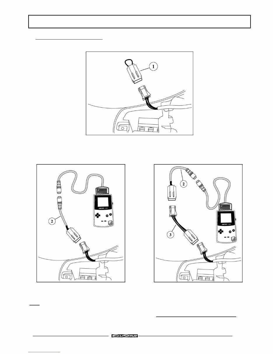
Connection of the diagnostic tool
1. Turn on the ignition (to unlock the ECU and authorise engine starting)
2. Remove the diagnostic plug loop (1)
3. Connect the diagnostic tool to the machine using:
a - Interface cable (2) for EFI system diagnostic b - Interface cable (2) + special interface (3) ref:
756449 for diagnostic of the ABS/PBS system
4. Turn on the diagnostic tool.
Note:
Never forget to re-connect the diagnostic plug loop. The loop provides the link between the
immobiliser module and the injection/ignition ECU, and is essential to be able to start the engine
Downloaded from www.Manualslib.com manuals search engine
SPECIAL IMPORTANT POINTS
Page : 7
Reproduction or translation, even partial, are forbidden without the written consent of Peugeot Motocycles
SPECIAL IMPORTANT POINTS
Fuel system
Before commencing work, clean the power unit.
The injection system is composed of precision components and cannot withstand impurities. Perfectly
clean working conditions are therefore essential.
Note:
Before carrying out any work, leave the engine to cool for a minimum of 2 hours.
Petrol is highly inflammable, do not smoke in the working area and avoid proximity to flames or sparks.
Work in a clear and well-ventilated area.
The fuel pipes must be changed if they show signs of wear, cracks, etc.
Moreover, the hoses and clips are specific and must only be replaced by the original genuine parts
Downloaded from www.Manualslib.com manuals search engine
TIGHTENING TORQUES
Page : 8
Reproduction or translation, even partial, are forbidden without the written consent of Peugeot Motocycles
TIGHTENING TORQUES
50 cc Engine
Cylinder head 1.2 m.daN
Cylinder casings 1 m.daN
Covers 1 m.daN
Inlet manifold 1 m.daN
Starter motor 1 m.daN
Rotor 4 m.daN
Stator 1 m.daN
Engine speed sensor. 1 m.daN
Turbine 1 m.daN
Drive pulley 4 m.daN
Driven pulley 4.5 m.daN
Spark plug 1 m.daN
Compressor 0.65 m.daN
Injection rail 0.65 m.daN
125-150 cc Engine
Cylinder head 2.3 m.daN
Cylinder casings 1 m.daN
Covers 1 m.daN
Starter motor 1 m.daN
Rotor 7 m.daN
Stator 1 m.daN
Engine speed sensor. 0.65 m.daN
Drive pulley 7 m.daN
Driven pulley 7 m.daN
Spark plug 1 m.daN
Injection rail 1 m.daN
Downloaded from www.Manualslib.com manuals search engine
SPECIAL TOOLS
Page : 9
Reproduction or translation, even partial, are forbidden without the written consent of Peugeot Motocycles
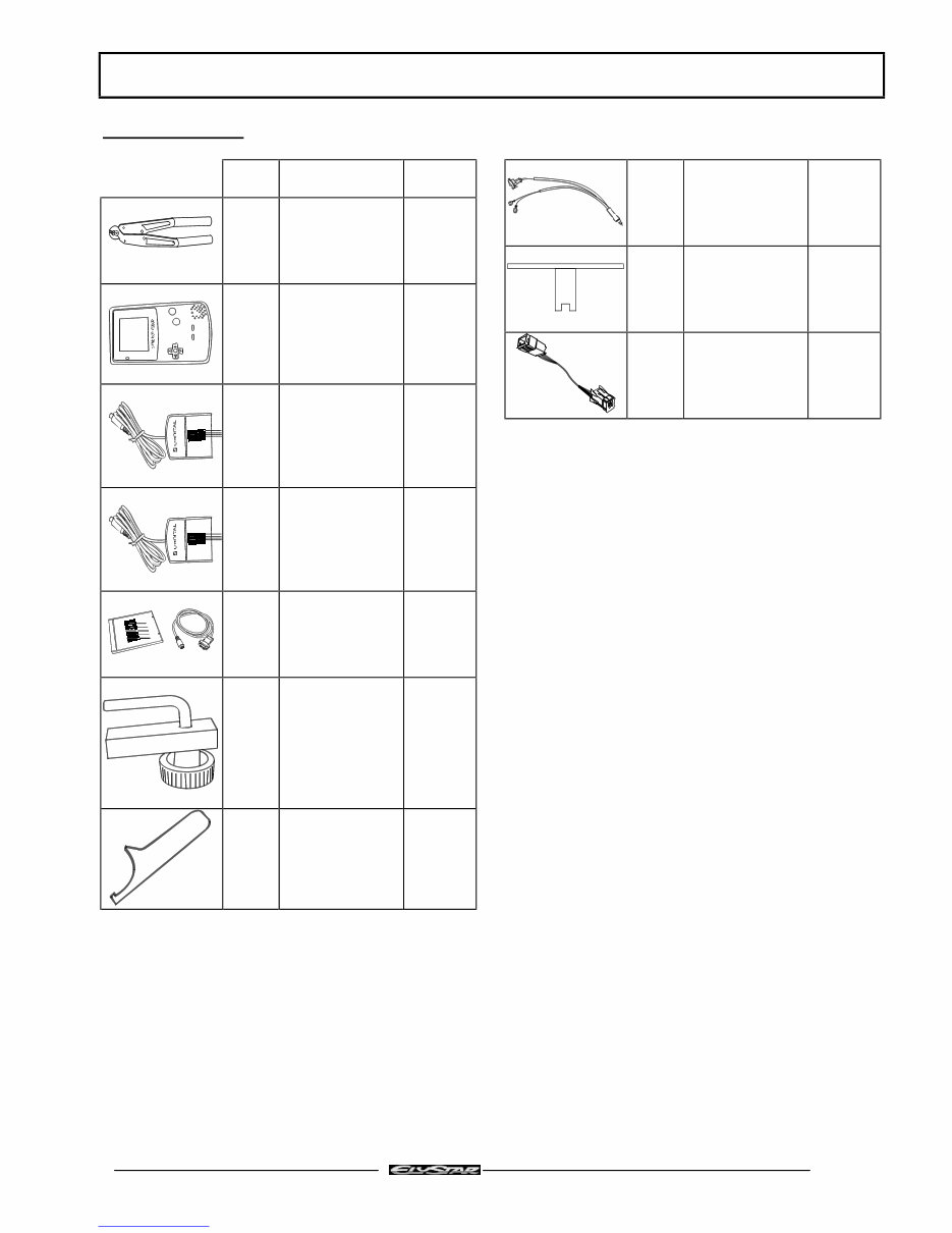
SPECIAL TOOLS
Tool N° Description Used with
750539 Tie-wrap pliers
755878 diagnostic tool
(Color Gameboy)
755806
755807
755806 French cartridge 755878
755807 Export cartridge 755878
755990 Diagnostic tool
update software
755878
755806
755807
755996 Hose clamp
756056 Tank ring spanner
756017 Petrol injection
power supply
harness
TSDI
756076 Tank gauge spanner
EFI
756449 ABS/PBS interface
cable for diagnostic
tool
755878
755806
755807
Downloaded from www.Manualslib.com manuals search engine
INSTRUMENT PANEL
Page : 10
Reproduction or translation, even partial, are forbidden without the written consent of Peugeot Motocycles
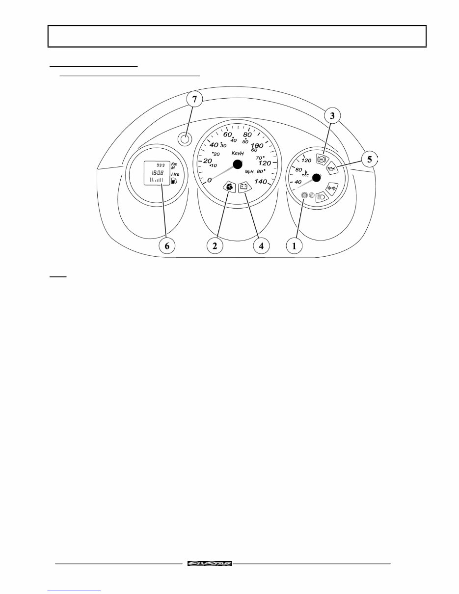
INSTRUMENT PANEL
Warning lights description and meanings
Note: The above diagram shows the Elystar 125-150 cc speedo
On the 50 cc Elystar, there is no the engine temperature gauge and ABS/PBS warning light
When ignition is turned on:
1 - The coded immobiliser diagnostic LED comes on (1) and goes off after 0.5 seconds
If there is an immobiliser fault, the LED flashes several times depending on the fault detected then stays on
2 - The EFI (Electronic Fuel Injection) or TSDI (Two Stroke Direct injection) diagnostic warning light (2)
comes on then goes off when the engine is started
If there is an injection system fault, the lamp flashes or stays on
3 – The ABS/PBS (Anti Blocking System/Powered Braking System) diagnostic warning light (3) comes on
then goes off once the vehicle is on the move (over 5 km/h) (Elystar only)
If there is an ABS/PBS fault, the lamp stays on
4 - The battery charge light (4) does not come on
However, this warning light can come on at under 11.6 V or over 15.8 V to show there is a fault in the battery
charging circuit
5 - The oil pressure warning light (5) comes on then goes off when the engine starts. This warning light comes
on when under 0.5 bar to indicate a drop in engine oil pressure (stop the machine as quickly as possible) (on
the Elystar 50 cc, this warning light is used for the separate lubrication system oil level, and comes on 3
seconds after turning on the ignition)
Downloaded from www.Manualslib.com manuals search engine
You're Reading a Preview
What's Included?
Fast Download Speeds
Online & Offline Access
Access PDF Contents & Bookmarks
Full Search Facility
Print one or all pages of your manual
$31.99
Viewed 21 Times Today


Secure transaction
What's Included?
Fast Download Speeds
Online & Offline Access
Access PDF Contents & Bookmarks
Full Search Facility
Print one or all pages of your manual
$31.99
- This complete factory service repair workshop manual is available for instant access on your computer, tablet, or smartphone.
- It covers all repairs, servicing, and troubleshooting procedures with detailed photos and diagrams, making it suitable for professional mechanics and DIY enthusiasts.
- The manual contains step-by-step instructions, highly detailed exploded diagrams, and pictures to guide you through each job correctly.
- You have the option to print out a single page or the entire manual.
- This is the full manual without any limitations or trial periods, and it can be used for life without the need for renewal or extra fees.
- It is fully compatible with all Windows and MAC computers.
Thanks for considering this item. Please click the button for more information.


