


s E R V I c E
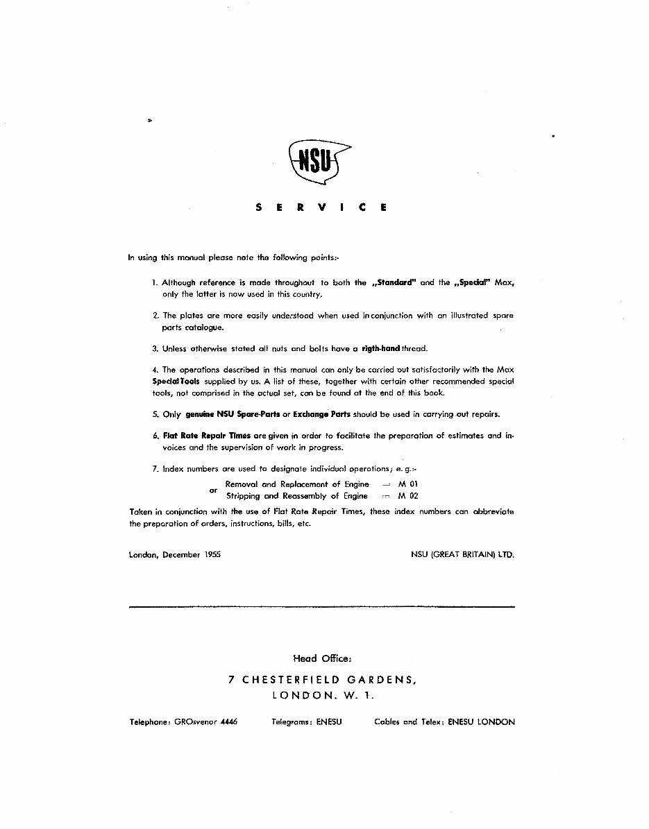
In using this manual please note the following points:-
1. Although reference is made throughout to both the ,Standard" and the ,Spedal" Max,
only the latter is now used in this country.
2. The plates are more easily understood when used in conjunction with an illustrated spare
parts catologue.
3. Unless otherwise stated all nuts and bolts have a rigth-handthreod.
4. The operations described in this manual con only be carried out satisfactorily with the Max
SpeclaiTools supplied by us. A list of these, together with certain other recommended special
tools, not comprised in the actual set, can be found at the end of this book.
5. Only genuine NSU Spare-Parts or Exchange Parts should be used in carrying out repairs.
6. Flat Rate Repair Times ore given in order to facilitate the preparotion of estimates and in-
voices and the supervision of work in progress.
7. Index numbers ore used to designate individual operations; e. g.:.
Removal and Replacement of Engine
or Stripping and Reassembly of Engine
M 01
M02
Token in conjunction with the use of Flat Rate Repair Times, these index numbers con abbreviate
the preparation of orders, instructions, bills, etc.
London, December 1955 NSU (GREAT BRITAIN) LTD.
Head Office:
7 CHESTERFIELD GARDENS,
LONDON. W. 1.
Telephone: GROsvenor 4446 Telegrams: ENESU Cables and Telex: ENESU LONDON
Downloaded from NSUSupermax.com
•
SERVICE
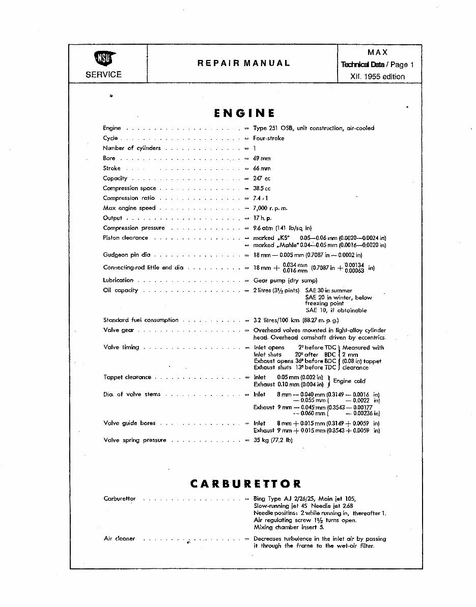
Engine
Cycle .
Number of cylinders
Bore
Stroke
Capacity
Compression space
Compression ratio
Max engine speed
Output
Compression pressure
Piston clearance
Gudgeon pin dia
Connecting-rod little end dia
lubrication
Oil capacity
Standard fuel consumption
Valve gear
Valve timing
Tappet clearance .
Dia. of vcilve stems
Valve guide bores
Valve spring pressure
Carburettor
Air cleaner
REPAIR MANUAL
MAX
Technical Data I Page 1
XII. 1955 edition
ENGINE
= Type 251 OSB, unit construction, air-cooled
= Four-stroke
=
1
= 69mm
=
66mm
= 247 cc
= 38.5cc
= 7.4:1
= 7,000 r. p.m.
= 17h.p.
= 9.6 otm (141 lbfsq in)
= marked .KSN 0.05-0.06 mm (0.0020-0.0024 in}
= marked .Mahle" 0.04--C-0.05 mm (0.0016-0.0020 in)
= 18 mm- 0.005 mm (0.7087 in-.: 0.0002 in)
18
0.034mm (
07087
. +0.00134
1
-n)
= mm + 0.016 mm · '" 0.00063
= Gear pump (dry sump)
= 2litres (3% pints) SAE 30 in summer
SAE 20 in winter, below
freezing point
SAE 10, if obtainable
= 3.2 litresflOO km (88.27 m.p.g.)
= Overhead valves mounted in light-alloy cylinder
head. Overhead camshaft driven by eccentrics
Inlet opens 2° before TDC l Measured with
Inlet shuts 200 after BDC 2 mm
Exhaust opens 36° before BDC J (0.08 in) tappet
Exhaust shuts 13° before TDC clearance
Inlet 0.05 mm (0.002 l Engine cold
Exhaust 0.10 mm (0.004•n) J
Inlet 8mm-0.040mm(0.3149-0.0016 in)
- 0.055 mm ( - 0.0022 in)
Exhaust 9 mm - 0.045 mm (0.3543- 0.00177
- 0.060 mm ( - 0.00236 in)
= Inlet 8 mm + 0.015 mm (0.3149 + 0.0059 in}
Exhaust 9 mm + 0.015 mm (0.3543 + 0.0059 in)
35 kg (77.2 lb)
CARBURETTOR
= Bing Type AJ 2j26j25, Main jet 105,
Slow-running jet 45 Needle jet 2.68
Needle positins: 2 while running in, thereafter 1.
Air regulating screw 1% turns open.
Mixing chamber insert 5.
= Decreases turbulence in the inlet air by passing
it through the frame to the wet-air filter.
Downloaded from NSUSupermax.com
REPAIR MANUAL
MAX
Technical Data/ Page 2
XII. 1955 edition
SERVICE
..
IGNITION
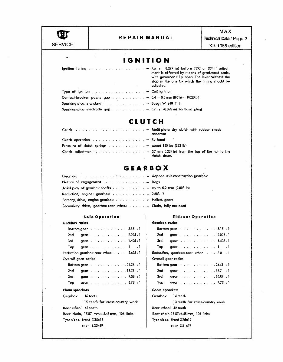
Ignition timing
Type of ignition
Contact-breaker points gap
Sparking plug, standard .
Sparking-plug electrode gap
= 7.6 mm (0.299 in) before TDC or 36° if adjust-
ment is effected by means of graduated scale,
with governor fully open. The lever without the
stop is the one by which the timing should be
adjusted. ·
= Coil ignition
= 0.4- 0.5 mm (0.016- 0.020 in)
= Bosch W 240 T 11
= 0.7 mm (0.028 in) (for Bosch plug)
CLUTCH
Clutch
Clutch operation
Pressure of clutch springs
Clutch adjustment
= Multi-plate dry clufch with rubber shock
absorber
= By hand
= about 160 kg {353 lb)
= 5.7 mm (0.224 in) from the top of the nut to the
clutch drum.
GEARBOX
Gearbox
Nature of engagement
Axial play of gearbox shafts
Reduction, engine: gearbox
Primary drive, engine-gearbox
Secondary drive, gearbox-rear wheel
Solo Operation
Gearbox ratios
Bottom gear
2nd gear
3rd gear
Top gear
Reduction gearbox-rear wheel
Overall gear ratios
Bottom gear
2nd gear
3rd
Top
gear
gear
Chain sprockets
Gearbox 16 teeth
3.15 :1
2.025:1
1.406 : 1
1 d
2.625:1
. 21.36 :1
. 13.73 : 1
9.53 : 1
6.78 : 1
1 5 teeth for cross-country work
Rear wheel 42 teeth
Rear chain, 15.87 mmx6.48mm, 106 links
Tyre sizes: front 3.25x19
rear 3.25x19
.
= 4-speed unit-construction gearbox
- Dogs
= up to 0.2 mm (0.008 in)
= 2.583:1
= Helical gears
= Chain, fully-enclosed
Sidecar Operation
Gearbox ratios
Bottom gear
2nd gear
3rd gear
Top gear
Reduction, gearbox-rear
Overall gear ratios
Bottom gear
2nd gear
3rd
Top
gear ·-
gear
Chain sprockets
Gearbox 14 teeth
wheel
3.15 :1
2.025:1
1.406: 1
1 :1
3.0 :1
. 24.41 : 1
. 15.7 :1
. 10.89 : 1
7.75 :1
} 3 teeth for cross-country work
Rear wheel 42 teeth
Rear chain 15.87x6.48 mm, 105 links
Tyre sizes: front 3.25x19
rear 3.5 x19
Downloaded from NSUSupermax.com
REPAIR MANUAL
SERVICE
MAX
Tectrical Page 3
XII. 1955 edition
WHEELS and BRAKES
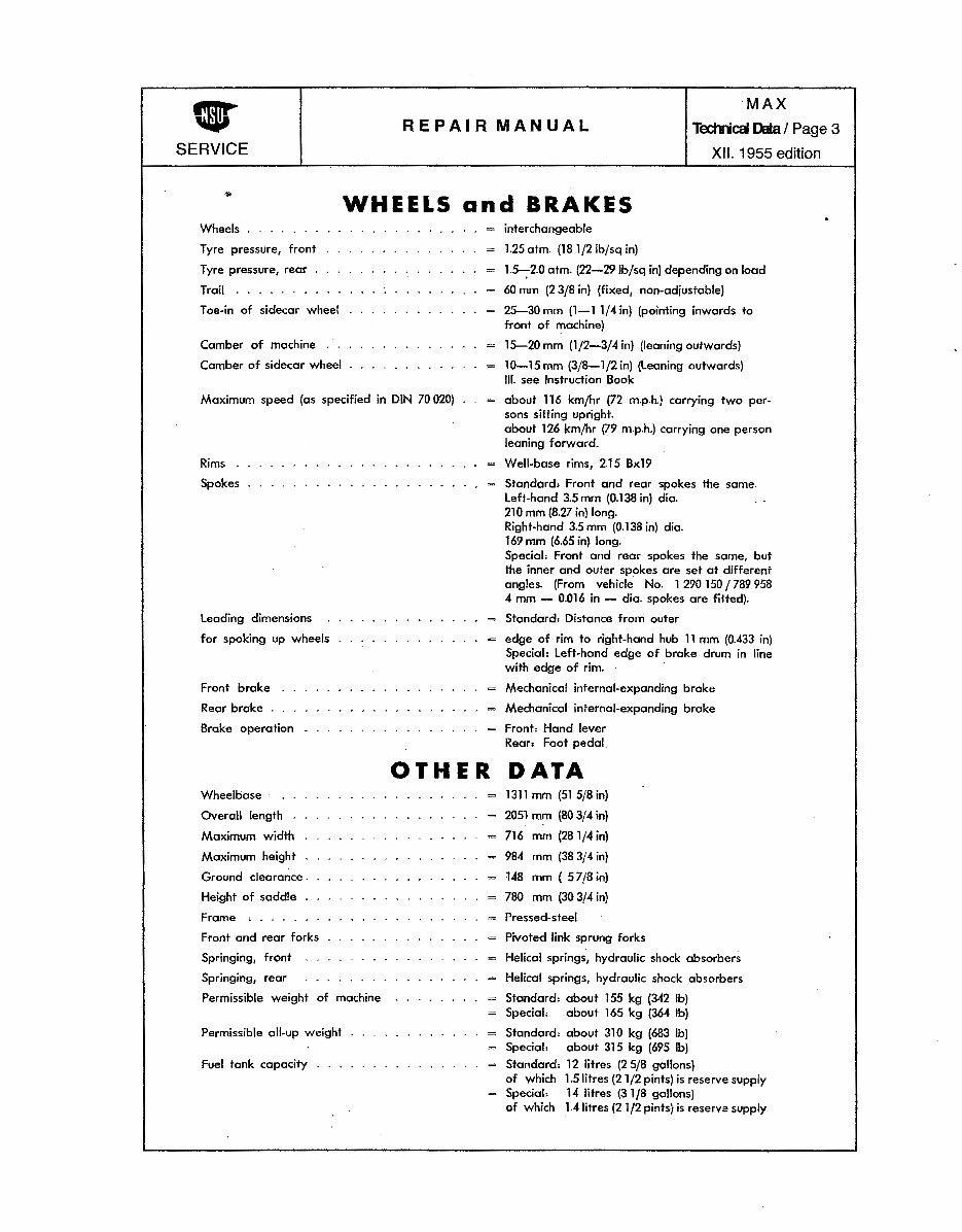
Wheels
Tyre pressure, front
Tyre pressure, rear
Trail
Toe-in of sidecar wheel
Camber of machine
Camber of sidecar wheel
Maximum speed (as specified in DIN 70 020)
Rims
Spokes
Leading dimensions
for spoking up wheels
Front broke
Rear brake
Broke operation
= interchangeable
= 1.25 atm. (181/21bfsq in)
= 1.5--:-2.0 atm. (22-291b/sq in) depending on load
= 60 mm (2 3/8 in) (fixed, non-adjustable}
= 25-30 mm (1-1 1/4 in) (pointing inwards to
front of machine)
= 15-20 mm (1/2-3/4 in) (leaning outwards)
= 10-15mm (3/8-1j2in) (Leaning outwards)
Iff. see Instruction Book
= about 116 kmfhr (72 m.p.h.) carrying two per-
sons sitting upright.
about 126 kmfhr (79 m.p.h.) carrying one person
leaning forward.
= Well-base rims, 2.15 Bx19
= Standard, Front and rear spokes the some.
left-hand 3.5 mm (0.138 in) dio. . .
21 0 mm (8.27 in} long.
Right·hand 3.5 mm (0.138 in) dia.
169 mm (6.65 in) long.
Specialo Front and rear spokes the same, but
the inner and outer spokes ore set at different
angles. (From vehicle No. 1 290 150 /789 958
4 mm- 0.016 in- dia. spokes ore fitted).
= Standard: Distance from outer
= edge of rim to right-hand hub 11 mm (0.433 in)
Special: left-hand edge of brake drum in line
with edge of rim.
= Mechanical internal-expanding brake
= Mechanical internal-expanding brake
= Fronh Hand lever
Rear: Foot pedal
OTHER DATA
Wheelbase
Overall length
Maximum width
Maximum height
Ground clearance .
Height of saddle
Frame '
Front and rear forks
Springing, front
Springing, rear
Permissible weight of machine
Permissible all-up weight
Fuel tank capacity
= 1311 mm (51 5/8 in)
= 2051rom (80 3/4 in}
= 716 mm (28 1/4 in)
= 984 mm (38 3!4 in)
= 148 mm (57/Bin)
= 780 mm (30 3/4 in)
= Pressed-steel
= Pivoted link sprung forks
= Helical springs, hydraulic shock absorbers
= Helical springs, hydraulic shock absorbers
= Standard: about 155 kg (342 lb}
= Special: about 165 kg (364 lb)
= Standard: about 310 kg (683 lb)
= Special: about 315 kg (695 lb)
= Standard: 12 litres (2 5/8 gallons)
of which 1.5 litres (21/2 pints) is reserve supply
= Special: 14 litres (31/8 gallons)
of which 1.4 fitres {2 1/2 pints) is reserve supply
Downloaded from NSUSupermax.com
REPAIR MANUAL
MAX
Engine I Page 1
XII. 1955 edition
SERVICE
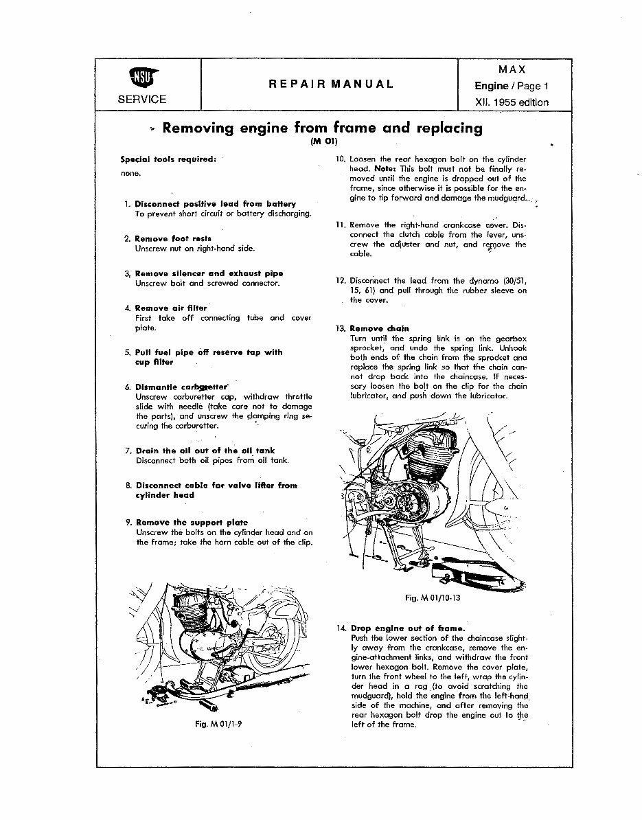
.. Removing engine from frame and replacing
(M 01)
Special tools required:
none.
1. Disconnect positive lead from battery
To prevent short circuit or battery discharging.
2. Remove foot rests
Unscrew nut on right-hand side.
3, Remove silencer and exhaust pipe
Unscrew bolt and screwed connector.
4. Remove air filter
First take off connecting tube and cover
plate.
5. Pull fuel pipe off reserve tap with
cup filter
6. Dismantle carbjaetter'
Unscrew carburetter cap, withdraw throttle
slide with needle (take care not to damage
the parts), and unscrew the clamping ring se-
curing the carburetter. '
7. Drain the oil out of the oil tank
Disconnect both oil pipes from oil tank.
8. Disconnect cable for valve lifter from
cylinder head
9. Remove the support plate
Unscrew the bolts on the cylinder head and on
the frame; take the horn cable out of the clip.
Fig. M 01/1-9
10. Loosen the rear hexagon bolt on the cylinder
head. Note: This bolt must not be finally re-
moved until the engine is dropped out of the
frame, since otherwise it is possible for the en-
gine to tip forward and damage the mudguard .... ,.
·'
11. Remove the right-hand crankcase cover. Dis-
connect the clutch cable from the fever, uns-
crew the adi1.1ster and nut, and the
cable. '-''
12. Disconnect the lead from the dynamo (30/51,
15, 61) and pull through the rubber sleeve on
the cover.
13. Remove chain
Turn until the spring link is on the gearbox
sprocket, and undo the spring link. Unhook
both ends of the chain from the sprocket and
replace the spring link so that the chain con-
not drop back into the chaincase. If neces-
sary loosen the bolt on the clip for the chain
lubricator, and push down the lubricator.
14. Drop engine out of frame.
Push the lower section of the chaincase slight.
ly away from the crankcase, remove the en-
gine-attachment links, and withdraw the front
lower hexagon bolt. Remove the cover plate,
turn the front wheel to the left, wrap the cylin-
der head in a rag .(to avoid scratching the
mudguard), hold the engine from the left-han{i_
side of the machine, and after removing the
rear hexagon bolt drop the engine out to the
left of the frame. ' ,.
Downloaded from NSUSupermax.com
REPAIR MANUAL
SERVICE
..
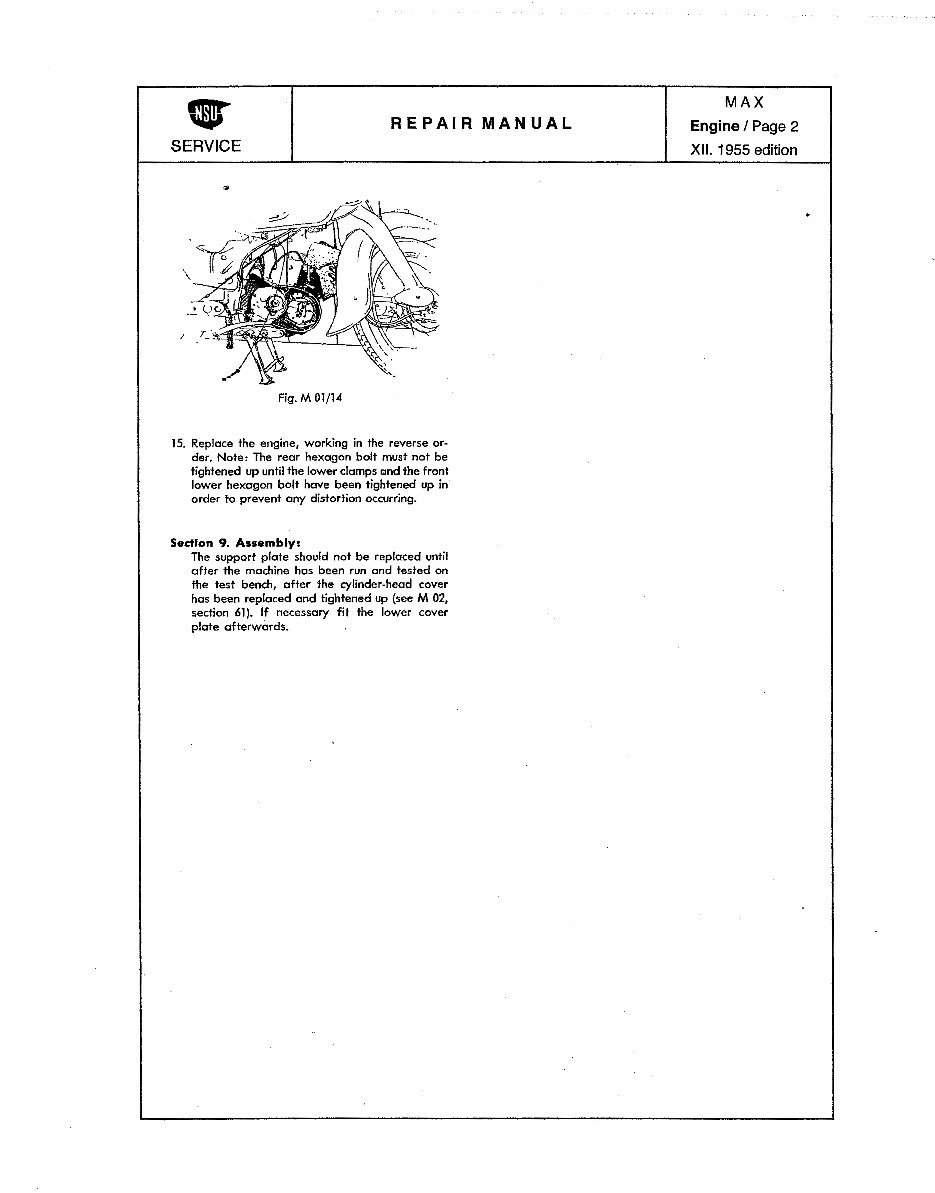
Fig. M Olfl4
15. Replace the engine, working in the reverse or-
der. Note: The rear hexagon bolt must not be
tightened up until the lower clamps ond the front
lower hexagon bolt have been tightened up in
order to prevent any distortion occurring.
Section 9. Assembly:
The support plate should not be replaced until
after the machine has been run and tested on
the test bench, after the cylinder-head cover
has been replaced and tightened up (see M 02,
section 61). If necessary fit the lower cover
plate afterwards.
MAX
Engine I Page 2
XII. 1955 edition
Downloaded from NSUSupermax.com
REPAIR MANUAL
MAX
Engine I Page 3
XII. 1955 edition
SERVICE
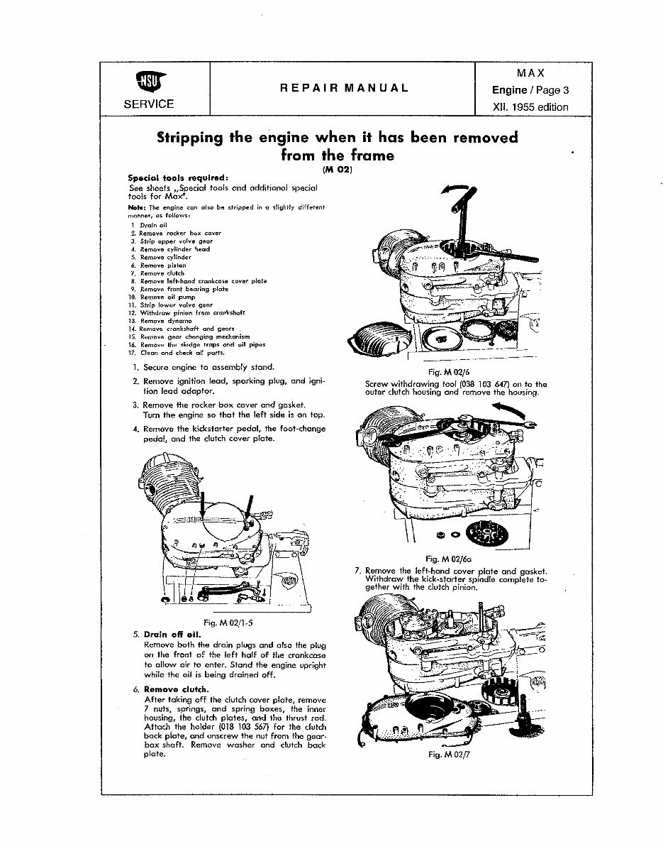
Stripping the engine when it has been removed
from the frame
Special tools required:
See sheets ,.Special tools and additional special
tools for Max".
(M02)
Note: The engine can also be stripped in a sJighHy different
manner, as
1. Drain oil
2. Remove rocker box cover
3. Strip upper valve gear
4. Remove cylinder head
5. Remove cylinder
6. Remove piston
7. Remove
8. Remove crankcase cover plate
9. Remove front bearing plate
10. Remove oil pump
1L Strip lower valve gear
12. Withdraw pinion from crankshaft
13. Remove dynamo
1-4. Remove crankshaft and gears
15. Remove gear changing mechanism
16. Remove the sludge traps and oil pipes
17. Clean and check att parts.
1. Secure engine to assembly stand.
2. Remove ignition lead, sparking plug, and igni-
tion lead adaptor.
3. Remove the rocker box cover and gasket.
Turn the engine so that the left side is on top.
4. Remove the kickstarter pedal, the foot-change
pedal, and the dutch cover plate.
Fig. M 02/1-5
5. Drain off oil.
Remove both the drain plugs and also the plug
on the front of the left half of the crankcase
to allow air to enter. Stand the engine upright
while the oil is being drained off.
6. Remove clutch.
After taking off the dutch cover plate, remove
7 nuts, springs, and spring boxes, the inner
housing, the dutch plates, and the thrust rod.
Attach the holder (018 103 567) for the dutch
back plate, and unscrew the nut from the gear-
box shaft. Remove washer and clutch bock
plate.
Fig.M02/6
Screw withdrawing tool (038 .1 03 647) on to the
outer dutch housing and remove the housing.
Fig. M 02f6a
7. Remove the left-hand cover plate and gasket.
Withdraw the kick-starter spindle complete to-
gether with the dutch pinion.
Fig. M02{1
Downloaded from NSUSupermax.com
REPAIR MANUAL
MAX
Engine I Page 4
XII. 1955 edition
SERVICE
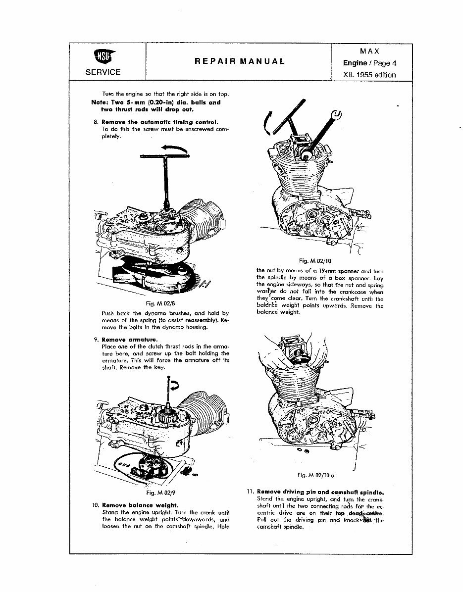
Tum the engine so that the right side is on top.
Note: Two 5-mm {0.20-in) dia. balls and
two thrust rods will drop out.
8. Remove the automatic timing control.
To do this the screw must be unscrewed com-
pletely.
Fig. M02/8
Push bock the dynamo brushes, and hold by
means of the spring (to assist reassembly). Re·
move the bolts in the dynamo housing.
9. Remove armature.
Place one of the clutch thrust rods in the arma·
ture bore, and screw up the bolt holding the
armature. This will force the armature off its
shaft. Remove the key.
Fig. M02j9
10. Remove balance weight.
Stano the engine upright. Turn the crank until
the balance weight points'·"d&wnwards, and
loosen the nut on the camshaft spindle. Hold
Fig. M 02/10
the nut by means of a 19-mm spanner and turn
the spindle by means of a box spanner. Lay
the engine sideways, so that the nut and spring
wasQer do not fall into the crankcase when
they'come dear. Turn the crankshaft until the
baldnce weight points upwards. Remove the
balance weight.
.I
Fig. M 02/10 a
11. Remove driving pin and ca.mshaft spindle.
Stand the engine upright, and turn the crank-
shaft until the two connecting rods f6t' the ec-
centric drive are on their top .
Pull out the driving pin and knock.•ltt. ··the
camshaft spindle. ·
Downloaded from NSUSupermax.com
REPAIR MANUAL
MAX
Engine I Page 5
XII. 1955 edition
SERVICE
..
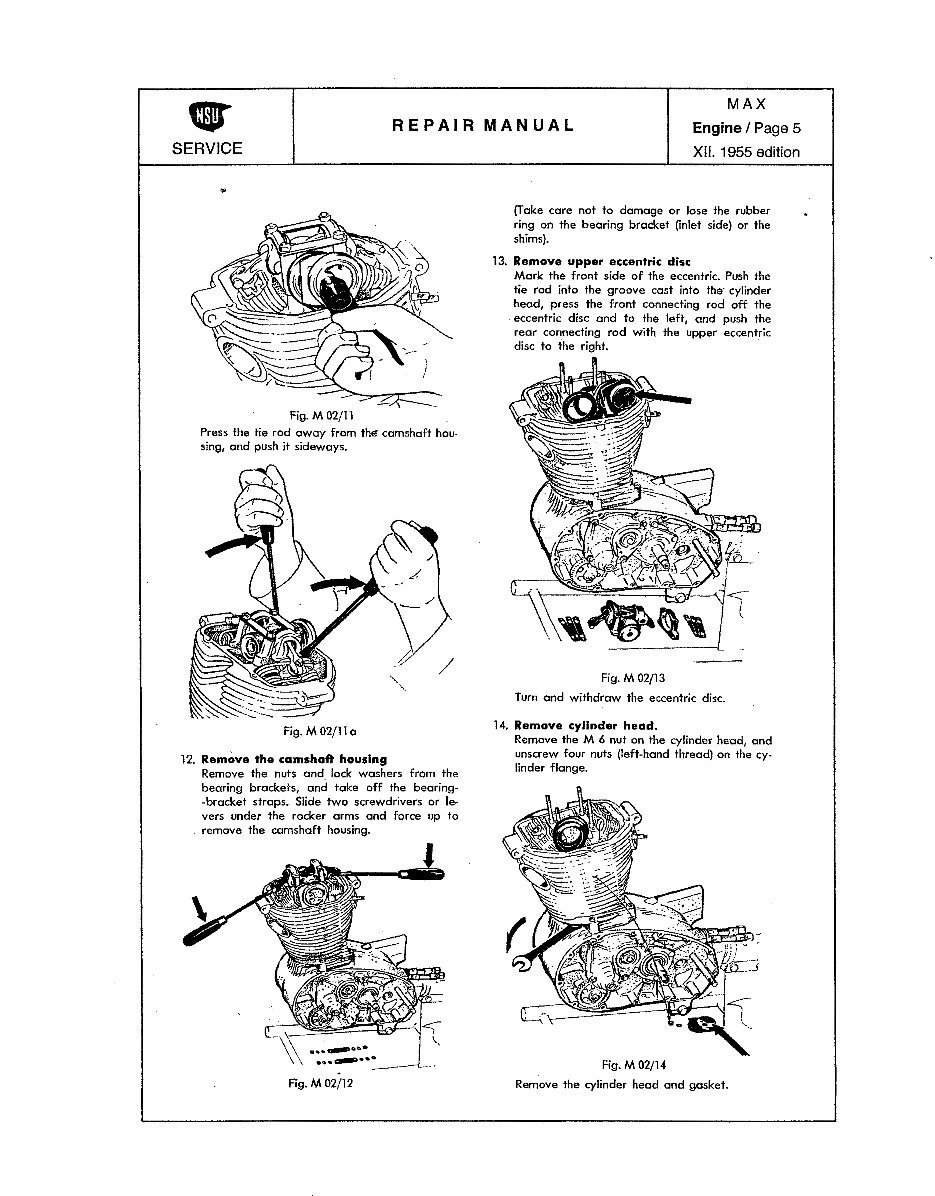
Fig. M 02/11
Press the tie rod away from the- camshaft hou-
sing, and push it sideways.
Fig. M 02/11 a
12. Remove the camshaft housing
Remove the nuts and lock washers from the
bearing brackets, and take off the bearing-
-bracket straps. Slide two screwdrivers or le-
vers under the rocker arms and force up to
remove the camshaft housing.
Fig. M02/12
(Take care not to damage or lose the rubber
ring on the bearing bracket (inlet side) or the
shims}.
13. Remove upper eccentric disc
Mark the front side of the eccentric. Push the
tie rod into the groove cast into the· cylinder
head, press the front connecting rod off the
eccentric disc and to the left, and push the
rear connecting rod with the upper eccentric
disc to the right.
Fig. M 02/13
Turn and withdraw the eccentric disc.
14. Remove cylinder head.
Remove the M 6 nut on the cylinder head, and
unscrew four nuts (left-hand thread) on the cy-
linder flange.
Fig. M 02/14
Remove the cylinder head and gasket.
Downloaded from NSUSupermax.com
REPAIR MANUAL
MAX
Engine I Page 6
XII. 1955 edition
SERVICE
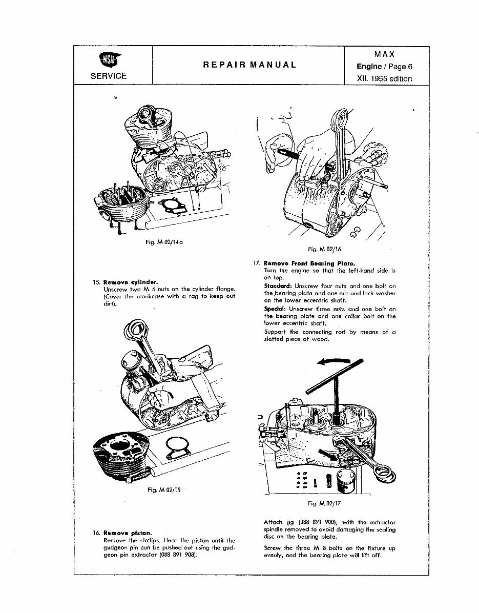
Fig. M 02jl4a
15. Remove cylinder.
Unscrew two M 6 nuts on the cylinder flange.
(Cover the crankcase with a rag to keep out
dirt).
Fig. M02/15
16. Remove piston.
Remove the circlips. Heat the piston until the
gudgeon pin can be pushed out using the gud-
geon pin extractor (088 891 908).
(
\.
Fig. M02/16
17. Remove Front Bearing Plate.
Turn the engine so that the left-hand side is
on top.
Standard: Unscrew four nuts and one bolt on
the ,bearing plate and one nut and lock washer
on the lower eccentric shaft.
Spedal: Unscrew three nuts and one bolt on
the bearing plate and one collar bolt on the
lower eccentric shaft.
Support the connecting rod by means of a
slotted piece of wood.
Fig. M02fl7
Attach jig (088 891 900), with the extractor
spindle removed to avoid damaging the sealing
disc on the bearing plate.
Screw the three M 8 bolts on the fixture up
evenly, and the bearing plate will lift off.
Downloaded from NSUSupermax.com
You're Reading a Preview
What's Included?
 Lifetime Access
Fast Download Speeds
Online & Offline Access
Access PDF Contents & Bookmarks
Full Search Facility
Print one or all pages of your manual
$33.99
NSU max motorcycle manuals
Viewed 76 Times Today

What's Included?
Lifetime Access
Fast Download Speeds
Online & Offline Access
Access PDF Contents & Bookmarks
Full Search Facility
Print one or all pages of your manual
$33.99

Secure transaction
What's Included?
Lifetime Access
Fast Download Speeds
Online & Offline Access
Access PDF Contents & Bookmarks
Full Search Facility
Print one or all pages of your manual
Description
These NSU Max motorcycle repair manuals are essential resources for both professional mechanics and DIY enthusiasts. The manuals cover detailed repair and maintenance procedures for the Max and Super Max models. Whether you are working on engine overhauls, electrical systems, or chassis maintenance, these manuals provide comprehensive guidance. The file format for these manuals is .PDF, ensuring easy access and compatibility across various devices.


