TABLE OF CONTENTS DESIGNATION PAGES Technical Specifications 1 Tools (special service) 2-6 Use of the Stroke Limiter 7 Engine Removal 8, 9 Refitting the Engine on the Frame 10, 11 Disassembling the Engine 12, 13 Piston Cylinder Matching 14 Examination of the Cylinder Head and Cylinder 15,16 Reassembling the Engine 17-22 Decarburizing the Engine 23 Removing-Decarburizing-Refitting the Exhaust 24, 25 Testing Ignition Timing 26, 27 Removing and Refitting the Flywheel Magneto 28, 29 Adjusting the Contact Breaker and Ignition Timing 30, 31 Removing and Reinstalling the Carburetor 32, 33 Disassembly and Reassembly of the Carburetor 34, 35 Description and Operation of the MOBYMATIC Variator 36 Variator (components parts) 37 Removing the Variator 38, 39 Disassembly and Reassembly of the Variator 40-42 Adjusting and Refitting the Variator 43, 44 Removing-Refitting-Disassembling-Reassembling the Clutch 45, 46 Removing and Refitting the Driven Pulley 47, 48 Removing and Refitting the Crankgear, Replacing Crankgear Bushings 49, 50 Replacing Upper Engine Mounting Flexible Bushings 51-53 Replacing Cables 54, 55 Replacing the Frame 56-58 Removing the Main Fork Assembly 59, 60 Refitting the Main Fork Assembly, Removing and Refitting the Fork Complete 61 Replacing Fork Bushings and Springs 62 Removing the Handlebars 63 Removing the Steering Head Assembly 64 Refitting the Steering Head Assembly 65 Removing and Refitting the Front and Rear Wheels 66
Replacing the Brake Shoes 68 Removing the Center Stand, the Saddle, Replacing the Pedal Chain and the Engine Drive Chain 69, 70 Replacing the Front Wheel Adjustment Cones, Cups, and Balls 71, 72 Replacing Rear Wheel Ball Bearings 73, 74 Checking Wheel Alignment 75 Removing and Refitting the Front and Rear Fenders 76, 77 Removing and Refitting the Shock Absorbers and the Swing Arm 78, 79 Trouble Shooting Guide 80-84 Wiring Diagram 12 Volt 85 Wiring Diagram 6 Volt 87
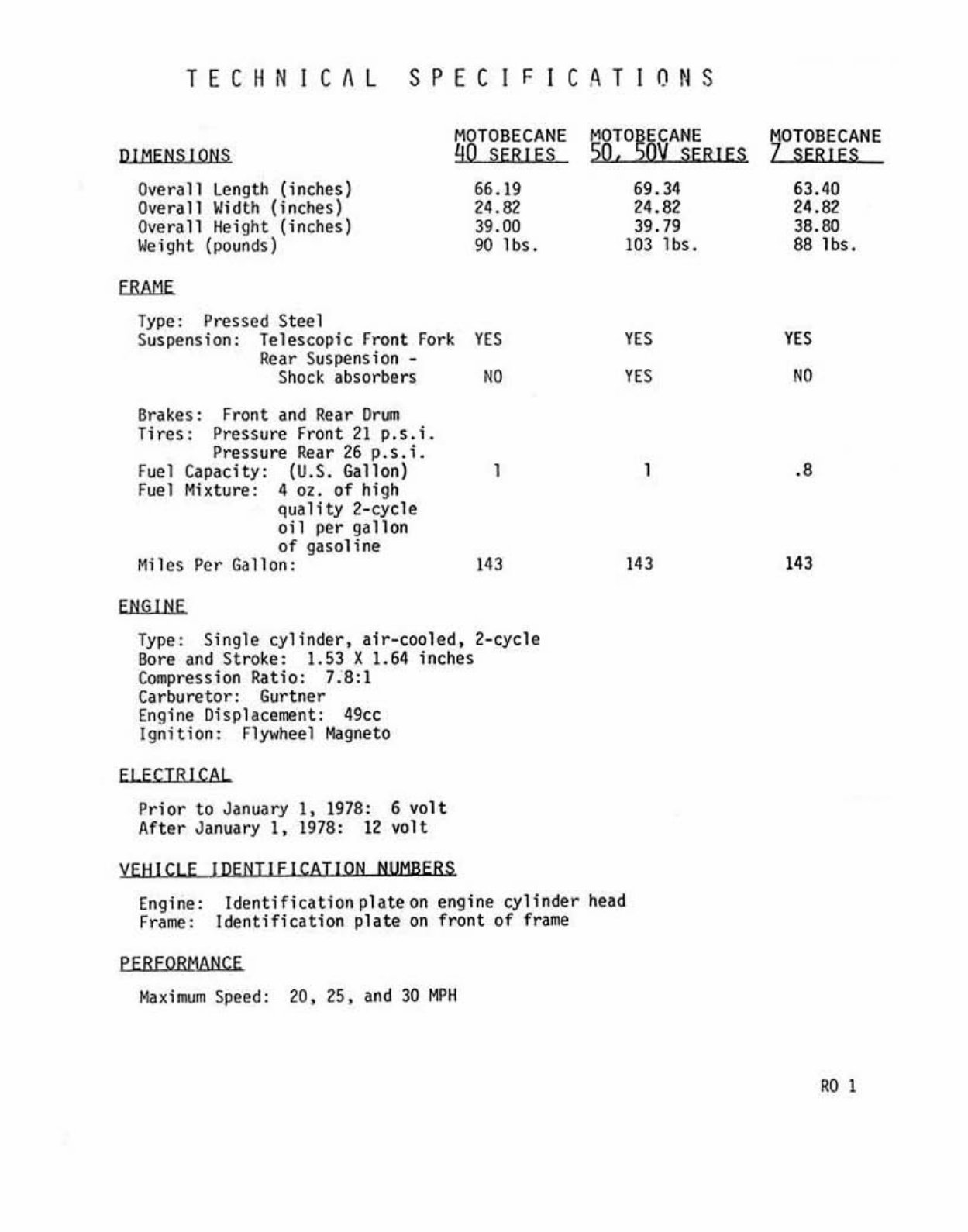
TECHN1Cfll SPEC I FIC,tIT ION S DIMENSIONS Overall Length (inches) Ove rall Width ( i nches) Ov erall Hei9ht ( inches) Weight (pounds) FRAME Type: Pressed Steel Suspens ion : Telescopic Fl"1)nt For~ Rea r Suspension - Shod ab sorbers 8n ~e s: Fr on t and Rear Or \lll Tires: Pr essu re F ront 21 p.s.i. Pressure Rear 26 p.s. i. Fuel Ca pacity: (U.S. Gallon) Fuel M hture: 4 o ~ . of hig h q ua lity 2-cycle oil per gallon of gasol ine Miles Per Gallon : ENGINE M8T O BECANE q SER IE S 66.19 24.82 39 . 00 90 lbs . YES " , '" Type: Single cylin der, air-cooled, 2-cycle So re and St ro ke: 1.53 X 1.64 i nches Compress i on R at io: 7.8: 1 Carburetor : Gurtner Engine Displacement: 49cc Ign ition: Flywheel Mo!gneto EI EC TR ICAL P ri or to January I, 1978: 6 volt After January I, 1978 : 12 volt y EH! CLE I DENT! E J CAT! ON NUMBERS 58;O~O§A~iR IES 69.34 24.82 39 . 79 103 Ibs. >E' YES , '" Engin e: Iden tifi ca t io nphteon en gin e cylinder head Fra me : Identificatio n plate on front of frame PER FORMANCE Mo! ~ irnum Speed: 20, 25, and 30 MPII ~TOBECANE SERIES 63 . 40 24 .82 38.80 88 lbs. YES NO .8 143 ROY
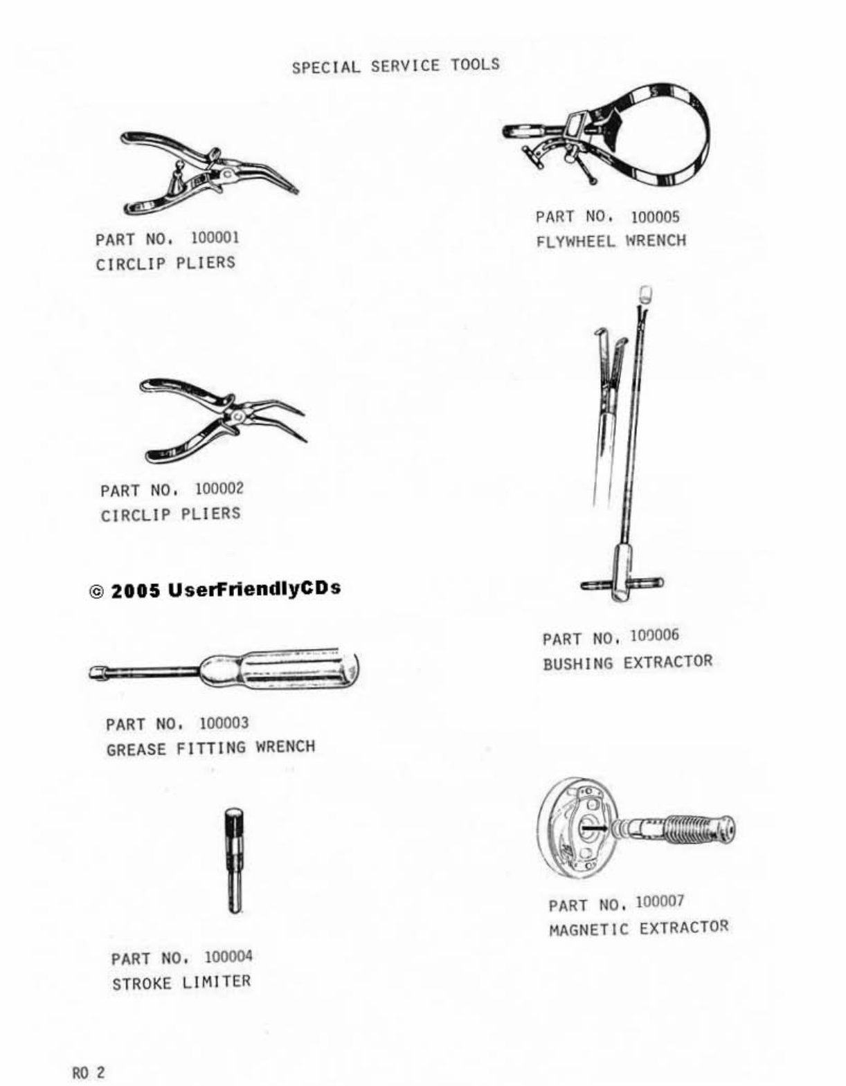
PAR T N O. 100001 CIRCLIP PLIERS PAR T NO. 100002 CI RC LI P P LI ERS SPEC I AL SERV I CE TOOLS @ 2115 UserFriendlyCDs ." PAR T NO. 100003 GR EAS E F ITT I NG W RE N CH PART N O. 1000I)I STRO KE LI MiT ER PART NO. 100005 FLYWHEEL WRENCH PART NO. 100006 BUSHING EX TRACTOR PART NO. 100007 HAG NETIC EXTRACTO~
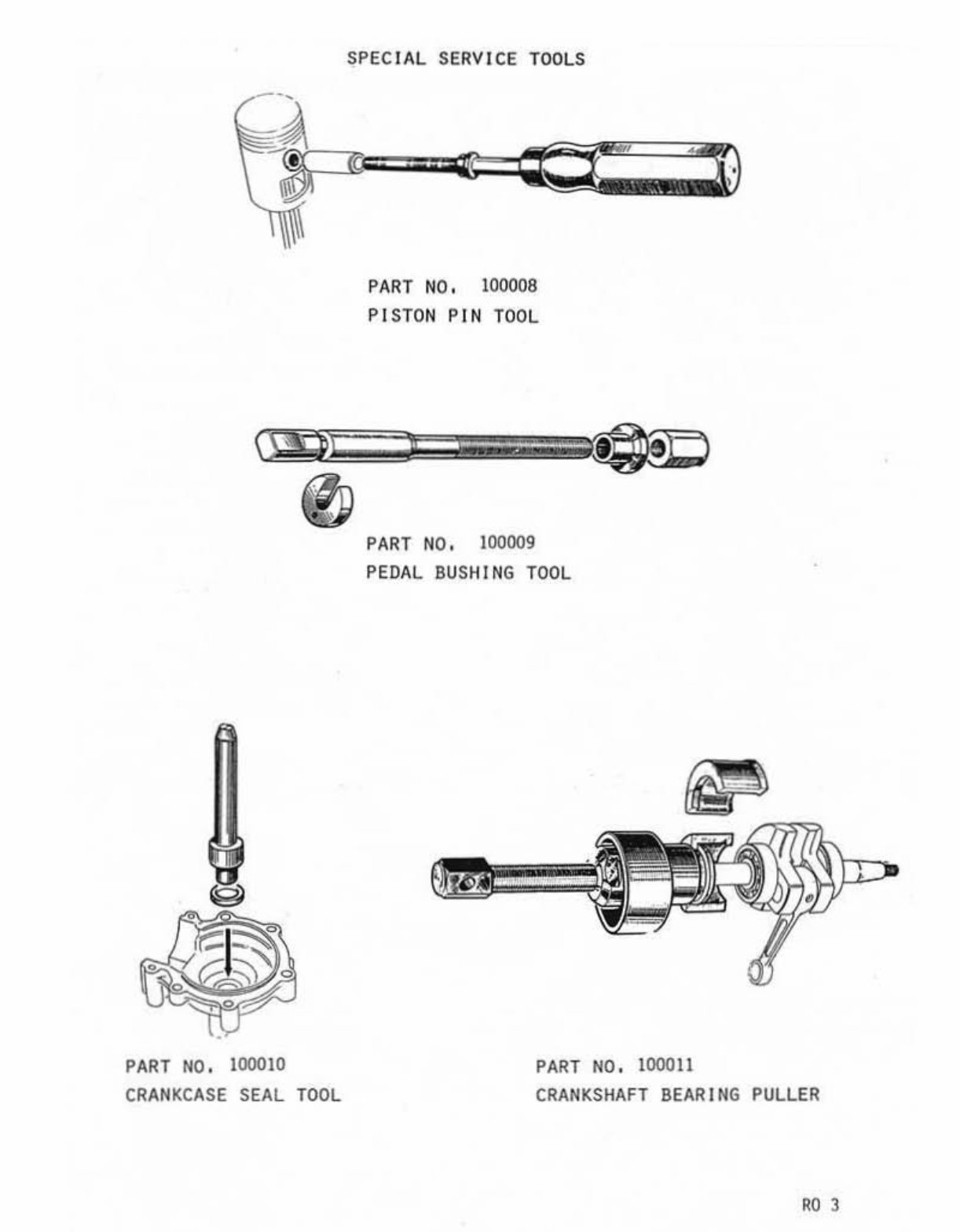
PART NO . 100010 CRANKCASE SEAL TOOL SPEC I AL SERV I CE TOOLS PART NO. 100008 PISTON PIN TOOL PART NO . 100009 PEDAL BUSHING TOOL PART NO. 100011 CRANKSHAFT BEARING PULLER '03
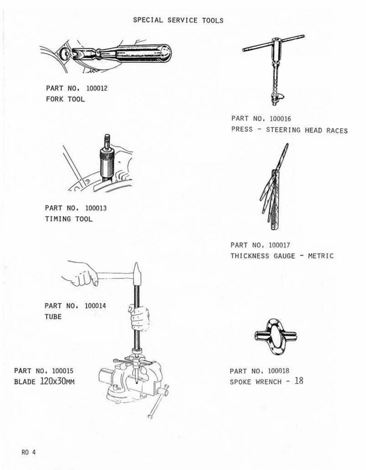
PART NO. 100012 FORK TOOL PART NO . 100013 TI MI NG TOOL PAR T NO. 100014 TUBE PA RT NO. 100015 BLADE 120x30MM '" SPECIAL SERVICE TOOLS PART NO. 100016 PRESS - STEERING HEAD RACE S PART NO. 100017 THIC KNE SS GAUGE - M ETRIC PART NO. 100018 SPOKE WRENCH - 18
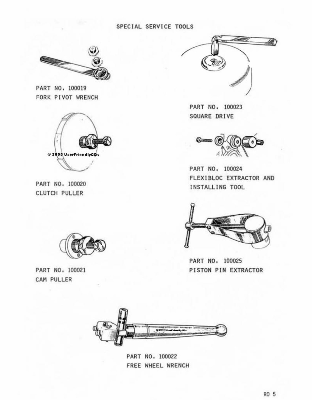
PART NO. 100019 FORK PIVOT WRENC H PART NO. IDlmO CLUTCH PULLER PART NO . 100021 CAM PULLER SPEC I AL SERVICE TOOLS PART NO. 100022 FREE WHEEL WRENCH PART NO. looon SQUARE DR I VE @- PART NO . 100024 FLEX I BLOC EXTRACTOR AND INSTALLING TOOL PART NO. 100025 PI STON PIN EXTRACTOR '"
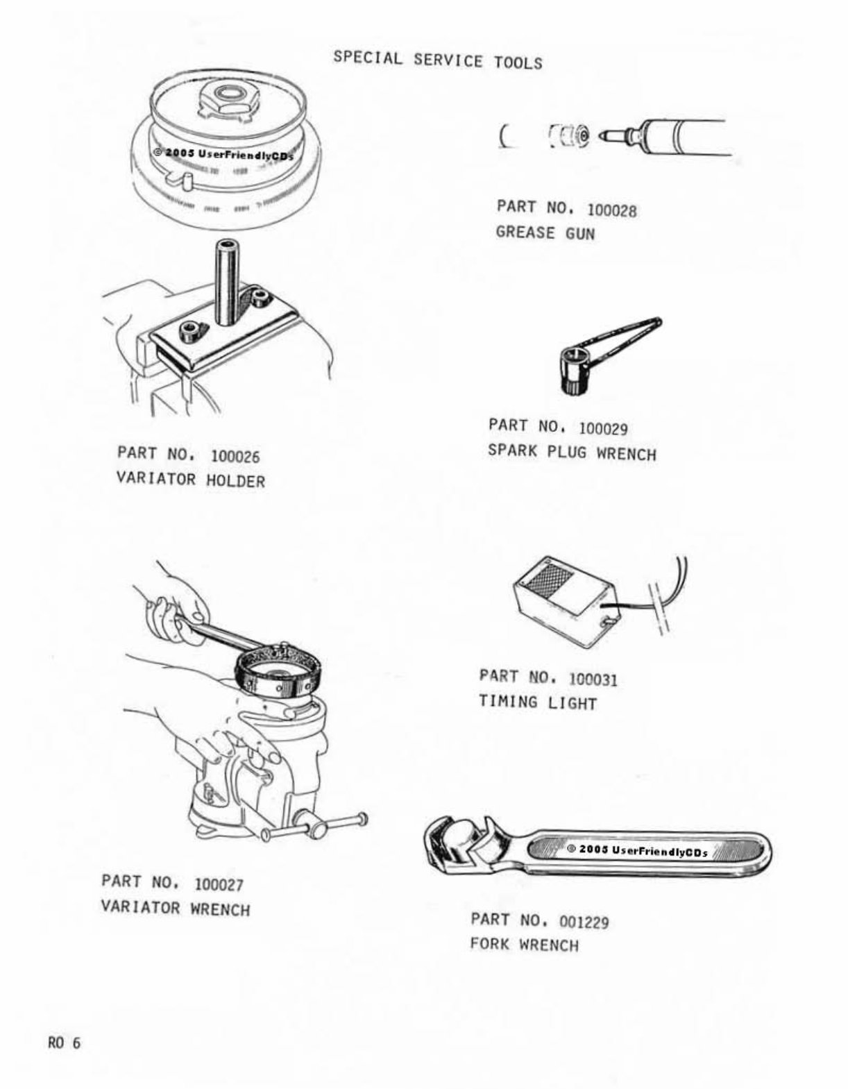
'06 PART NO. 100026 VARIATOR HOLDER PART NO. 100027 VARIATOR WREN CH SPECIAL SERVICE TOOL S PART NO. 100028 GREASE GUN PART NO. 100029 SPARK PLUG WRENCH PART NO. 100031 TIMING LIGHT PART NO, 001229 FORK W RENCH
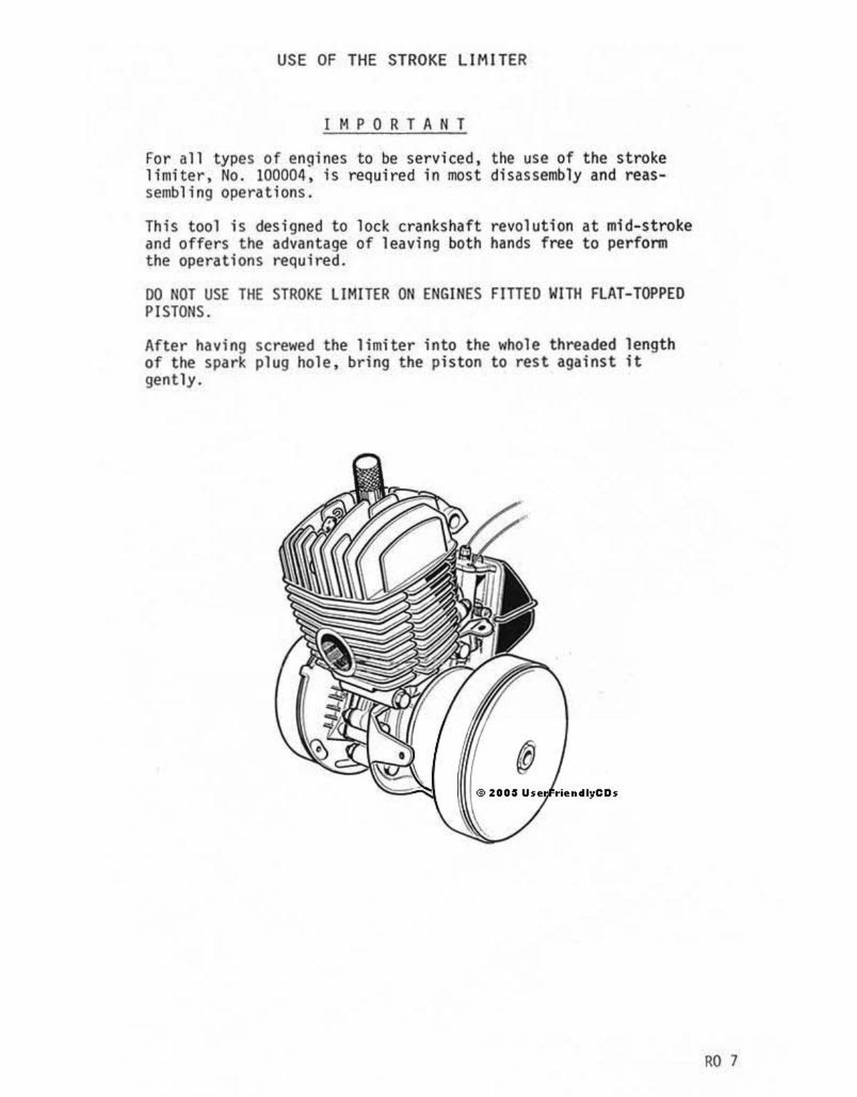
USE OF TH E STROKE LIMITER IMPORTANT for all types of engines to t>e serviced, the use of the stroke limiter, No. 100004, is required in most disass e mbly and reas- sembling operations. This tool Is designed to lock crank shaft revolution H mid-stroke and offers the advantage of leaving both hands free to per form the operations required. 00 NOT USE THE STROKE LIMITER ON ENGI N ES FITTED WITll FLAT-TOPPED PISTONS. After having screwed the l imite r in to t he whole threaded len gt h of the spa rk plug hole, bring the pis t on to rest against It gently. "07
You're Reading a Preview
What's Included?
Lifetime Access
Fast Download Speeds
Online & Offline Access
Access PDF Contents & Bookmarks
Full Search Facility
Print one or all pages of your manual
$31.99$41.99
Motobecane Moped Model 40, 50, 50V and 7 Service Repair Workshop Manual - *
This is a comprehensive service repair workshop manual for the Motobecane Moped Model 40, 50, 50V, and 7. It is available in English and compatible with Win/Mac operating systems. The manual covers both 6 and 12 volt models and includes detailed sections on technical specifications, special service tools, and the use of the stroke limiter. It also provides step-by-step procedures for engine removal, disassembly, reassembly, and decarburizing. Additionally, it includes instructions for removing and refitting various components such as the exhaust, carburetor, clutch, and crankgear. The manual also covers procedures for replacing cables, frame, fork assembly, wheels, brake shoes, and various bearings. It features fully bookmarked chapters for easy navigation and includes detailed illustrations, exploded diagrams, photos, and troubleshooting guides. Whether for tune-ups, regular maintenance, or repairs, this manual provides all the necessary technical details and instructions for professional mechanics and DIY enthusiasts.
Language: English
Format: PDF
Compatibility: Win/Mac
Reviews
Q&A
Recently Viewed
5,521,897Happy Clients
2,594,462eManuals
1,120,453Trusted Sellers
15Years in Business
Price:
Actual Price:
Motobecane Moped Model 40, 50, 50V and 7 Service Repair Workshop Manual - *