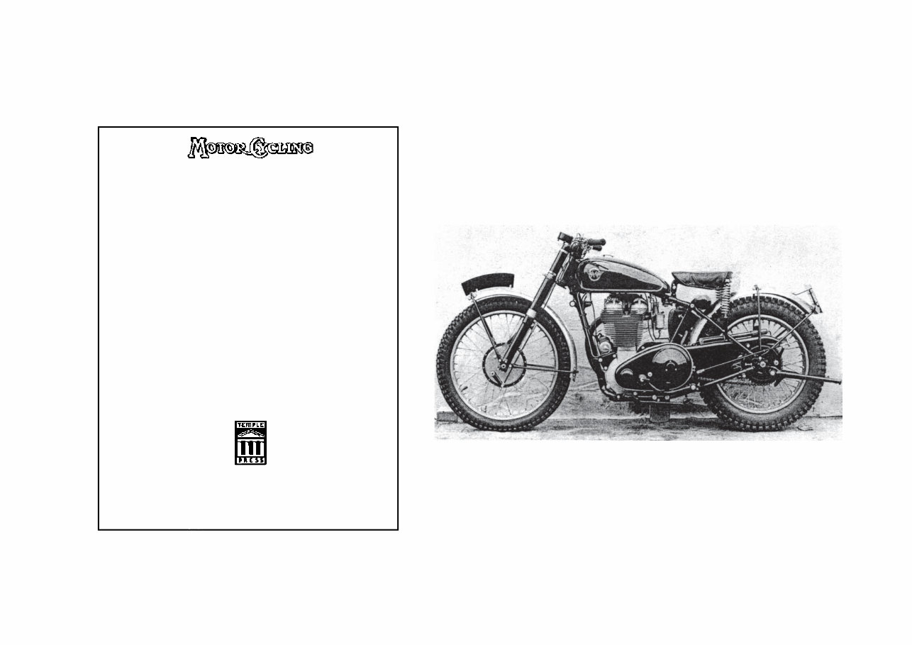
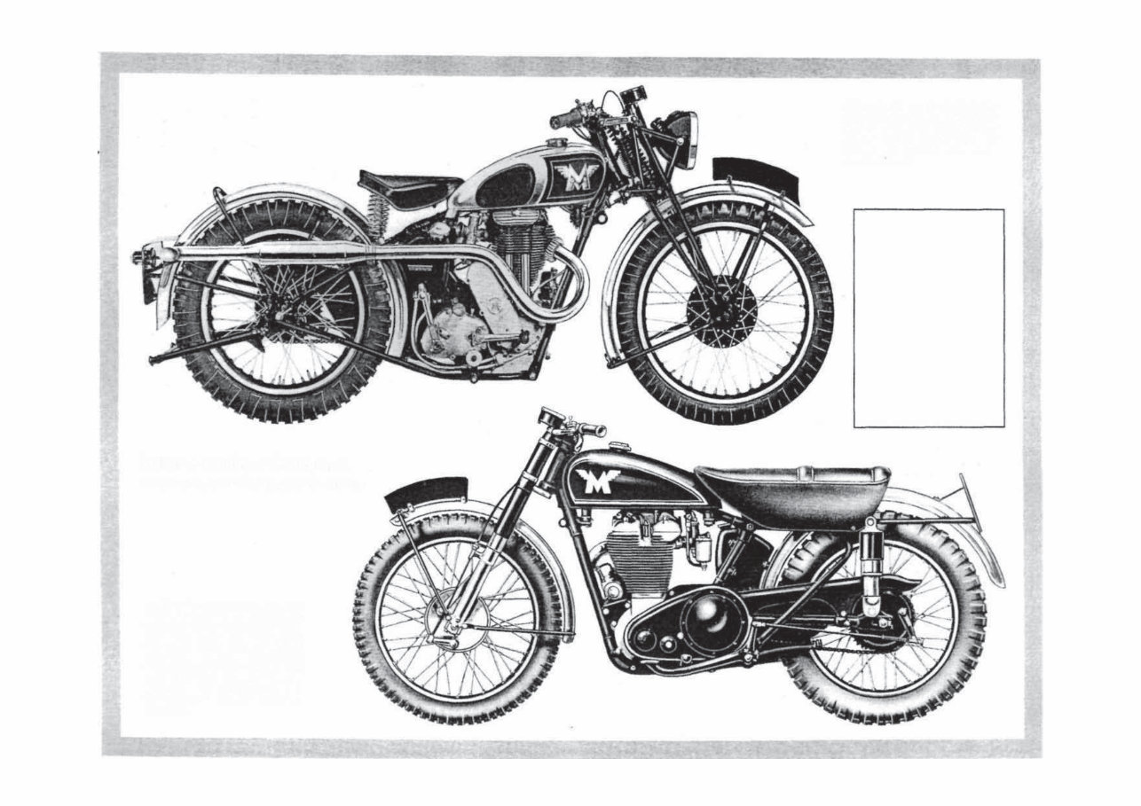
DEFINITIVE PHOTOGRAPHS MATCHLESS SINGLES 1939 -1955 1 Maker's definitive photographs by courtesy of Motorcycle Sport Again a factory photograph. The 1954-season 500 cc G80CS in- troduced from September 1953 with the new for that year full-width front hub of 7-inch diameter brake, lightweight welded front frame and a twin seat. Rear legs are AMC's own Jampots. The alloy motor has the magneto forward mounted of course IMPORTANT NOTE Since the text was written for the original book, AMC Ltd has passed into other hands and the Woolwich factory has been demolished. Comments about over- haulers refering to the makers should be read in this light. Spares and specialist service are now concentrated in the hands of a few UK dealers who include Messrs Hamrax and Joe Francis Motors — Reg Hide (Left) Another maker's definitive photograph showing the 350 cc G3C as it was in 1938 with of course girder forks and the stylised M symbol on the chromed tank www.ajs-matchless.info
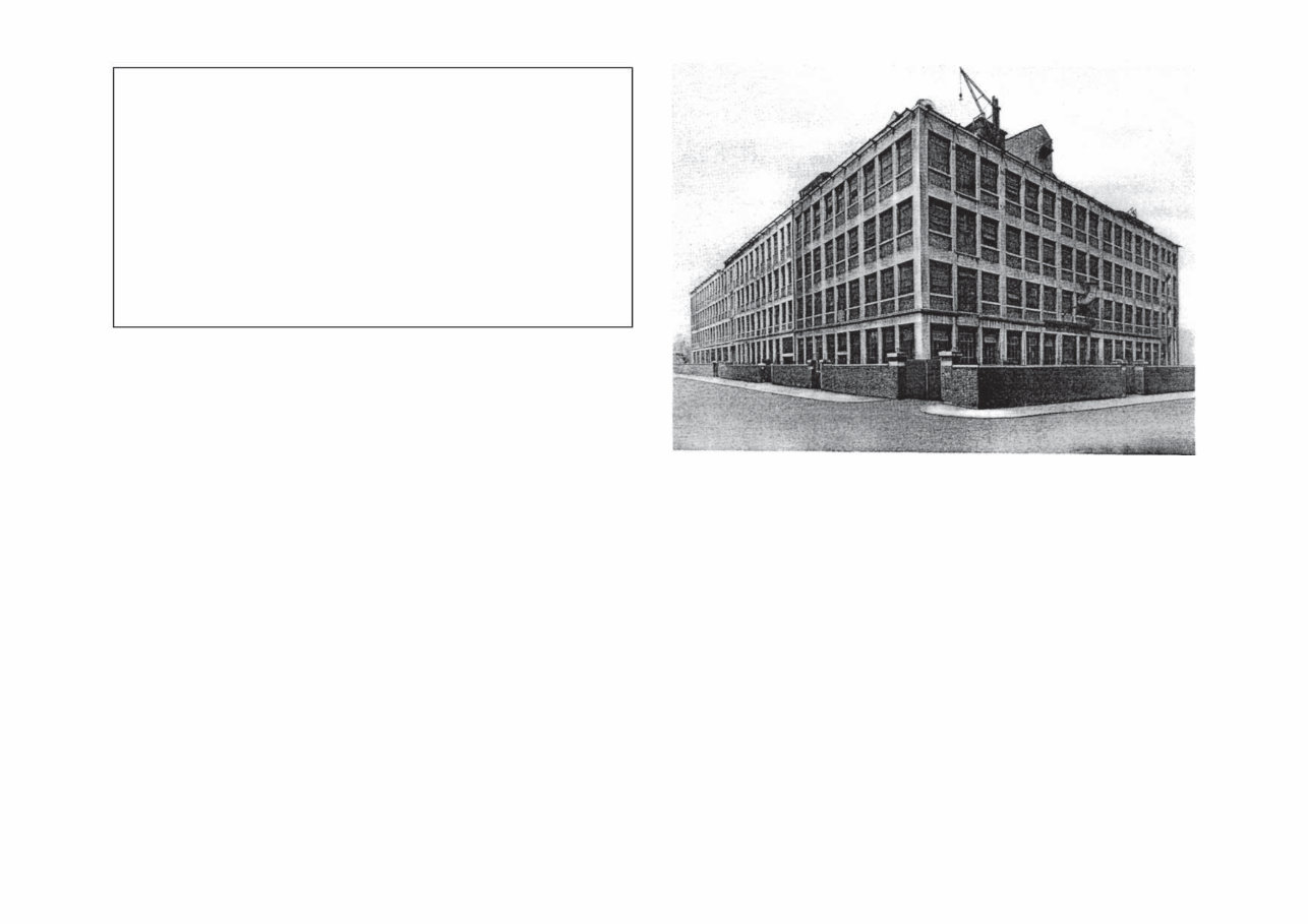
FOREWORD TO THE ORIGINAL BOOK This bookis a practical guide carefully compiled to enable both the new owner and the expert to carry out routine maintenance, complete overhauls, and to service those Matchless single-cylinder machines built between 1939 and 1955. It will also be of assistance to dealers' service staff as the comprehensive information provided in the text is culled from extensive experience in servicing these machines. To obtain maximum efficiency, reliability, and long life from component parts, regular and systematic maintenance is essential. Performance, too, is likely to be improved if careful attention is given to the instructions outlined in these chapters. The aim throughout has been to guide the reader step by step through the sequence of dismantling and reassembly, paying particular attention to the elimination of defects, and so avoiding those trial and error methods which can prove so frustrating and, in the end, so expensive. Chapters are devoted to ex-WD machines, giving conversions that will improve performance; and to trials and scrambles machines. Technical data and illustrations of special tools recommended and used by the manufacturers are included in the text. Finally, the Publishers wish to make grateful acknowledgment to Associated Motor Cycles Ltd. for permission to reproduce a number of their copyright drawings in the text — BERNAL OSBORNE, Temple Press Ltd. An official photograph, courtesy of Motorcycle Sport, revealing the side and rear of the AMC factory at Plumstead, taken from the corner of Barrage Grove. The front, hidden here, is in the parallel Plumstead Road. Date is unknown but certainly is the early 1950's EDITOR'S PREFACE CONTENTS MATCHLESS SINGLES 1939 -1955 Definitive photographs 1 Decarbonising the engine 3 Servicing the engine 5 Overhauling the engine 9 Reassembling the engine 11 Pre-1955 Carburetters 14 The 1955 Monobloc carburetter 15 The CP-type Burman gearbox 16 The 852-type Burman gearbox 18 The clutch 18 Competition and scrambles models 19 The transmission 21 Forks and frames 22 Wheel bearings 25 Brake adjustment 26 Dynamos 26 Electrical equipment 27 Definitive photographs 28 et seq WD-G3Ldrawing 31 Definitive photograph 32 Wiring diagrams 33 et seq WD-G3L section 35 Useful data 37 et seq Engine design changes 40 et seq Permissible modifications 41 WD-G3L illustrated spares lists 42 et seq Maker's 1948 advertisement 59 The only workshop manual currently in print for Matchless 350 and 500 cc heavyweight singles, this book has had considerable extra material added by the publishers, Bruce Main-Smith Ltd. I have included an expanded WD-G3 and WD-G3L section which also features the factory illustrated spare parts lists in full on the military 350's; my thanks to Mr J.C. Martin of Letghton Buzzard for the loan of a set of mint-condition lists for this purpose. There is also a greatly increased amount of tabular information not found in the original Temple Press edition. The machines covered are of course those the factory came to call (at a later date) heavyweights, to distinguish them from the lightweight 250 and 350 cc ohv singles with their Phil Walker designed engines, gearboxes and frames introduced in June 1958 under both AJS and Matchless brand names by Associated Motor Cycles Ltd, then of Plumstead Rd, Woolwich, London SE18. The heavyweights can be instantly identified by their usage of a conventional oil tank behind the engine. The lightweights used no oil tank as such, lubricant being carried dry-sump-wise in a reservoir cast integrally with the crankcases. Though there are differences between early postwar AJS and Matchless heavyweights — notably the positioning of magneto and dynamo — this workshop manual will serve reasonably well for AJS too. Cams as manufactured by AMC were dual marked for both engines. Otherwise the motors were broadly similar and of course the cycle parts were identical other than for insignia and detail differences attendant on dynamo/magneto mountings and drives. Both types of Burman box are dealt with in full. The AMC gearbox was not phased in until April 1957 and is outside the scope of this manual — REG HIDE, Editor. 2 ........................................................................ ............................................................................... .................................................................................. ................................................................................................. ............................................................................ ............................................................................... ............................................................................ .................................................................... ..................................................................... ................................................................... ................................................................................ .............................................................. ........................................................................................ ...................................................................................... ......................................................................................... ....................................................................................... .................................................................................................. ................................................................................... ...................................................................................... .................................................................... ................................................................................ ............................................................................. .................................................................................... .................................................................... ........................................................................................ ......................................................... ............................................................................ www.ajs-matchless.info
1. DECARBONIZING THE ENGINE Beyond the limit of periodic maintenance and running adjustments, the work involved in decarbonizing a motorcycle engine is likely to constitute the first venture by the owner into the rather deeper technicalities of his machine. It is necessary, on an average, every 5,000 miles or so, to clean away carbon deposit from the inside of the power unit —just as one would clean a domestic flue and get more efficient combustion thereby. The job is an interesting one and usually not too difficult to be carried out with the tools in the kit plus the few additional items listed. The engine should be decarbonized only when it shows a definite sign of requiring attention. A gradual loss of power, poor compression, difficulty in starting, combined with an increase in petrol consumption, are all signs that decarbonizing is necessary. Conversely, some owners prefer to decarbonize at fixed intervals of between 5,000 to 8,000 miles. The risk in prolonging the interval between decarbonizing the engine is the possibility of exhaust-valve burning. Checking the compression from time to time will enable the owner to decide if compression is satisfactory or otherwise. It is imperative that the push-rod adjustment is correct, also that the throttle is fully open when this check is made. As work of this kind is usually carried out at week-ends, have ready the necessary tools and spares, so that it can be completed without delay. Suggested equipment for this purpose is listed below: (i) Decarbonizing gasket set. (ii) Valve spring compressor. (iii) Short length of rubber tubing with a ¼-in.-diameter bore with a nail through one end to act as a tommy bar. (iv) Scraping tool, such as a cheap 6-in. steel rule with the corners ground off. (v) Grinding paste, jointing compound, clean rag and washing gear. Dismantling To start dismantling, remove: (i) Petrol tank and petrol pipe. (ii) Exhaust pipe with silencer attached to it. (iii) Sparking plug after detaching H.T, cable. (iv) Throttle and air slides, leaving the needle in position. (Wrap these parts in clean rag and secure them to the handlebar lug to avoid possible damage.) (v) Rocker-box oil pipe; use two spanners, one for the pipe nipple nut, the other to prevent the union from turning. (vi) Cylinder head steady stay, if used. (vii) Valve-lifter cable (for engines after 1948). 3 (viii) Three nuts and washers securing the cover for the rocker box; take off the cover, turn the engine until both valves are closed then release all bolts securing the rocker box to the cylinder head. Tilt upwards the right side of the rocker box and extract the two long push-rods. The rocker box can now be lifted off. Whilst the two push-rods are identical, it is preferable to refit them in the original position. They should be marked suitably for correct order of replacement. Remove: (ix) Two valve end caps (for engines before 1949), then the four cylinder-head holding-down bolts; the cylinder head can now be taken away. If it is difficult to separate the cylinder head from the barrel, place a short piece of wood under the exhaust port and give the free end a series of light blows to cause separation. Remove: (x) Push-rod cover tubes; watch for a thin steel washer which may be fitted on each tube below the sealing rubbers. (xi) Carburetter mixing body and float chamber attached* This can be dealt with later. In all probability the rocker-box gasket or pieces of it will stick to the cylinder head. These can be removed with the steel rule previously mentioned, taking care to ensure that particles do not obstruct the oil drilling in the cylinder head. Before removing the valve springs and valves, scrape the carbon deposit from the cylinder-head sphere, also from the heads of both valves. The small amount of carbon remaining can be removed after the valves have been extracted. To remove both valves, a valve-spring compressor is required. The springs should not be compressed unduly and only sufficient to extract the valve collets. A sharp, light blow on the valve collar will help to separate the collar from the collets. On the 500 cc models both valves are similar in size, but different in material. Valves are marked IN or EX on the valve end above the collet groove. On the 350 cc models the inlet-valve head is larger in diameter than the exhaust. With valves removed, scrape off the residue of carbon from the cylinder head, remove also all traces of burnt oil or carbon from inside the exhaust-valve guide, using a piece of emery cloth (most important on engines made before 1949), then get rid of all particles of carbon from the ports and valve guides before starting to grind-in the valves. Scrape the exhaust-valve stem and head; if emery cloth is used on the valve stem, clean and polish with an up-and-down movement, not rotary, as the valve stems are hard-chromed during manufacture. A short piece of rubber tubing of ¼ in. internal diameter, pushed over the end of the valve, is a suitable tool for valve grinding. To grind the valves, apply a little fine-grinding paste on the valve face, insert the valve into the head and press the rubber tube on to the valve end. Holding the rubber tubing, pull the valve lightly on to its seating and turn the valve forward and backwards, raising the valve occasionally off its seating, and continue the process until the grinding compound ceases to "bite." When an even matt surface is seen on both the valve and the seating in the head, grinding is complete. Badly pitted valves, or valve seats, should be reseated by refacing the valve and recutting the valve seat in the cylinder head. The valve angle is 45°. Excess valve MATCHLESS SINGLES 1939 -1955 www.ajs-matchless.info
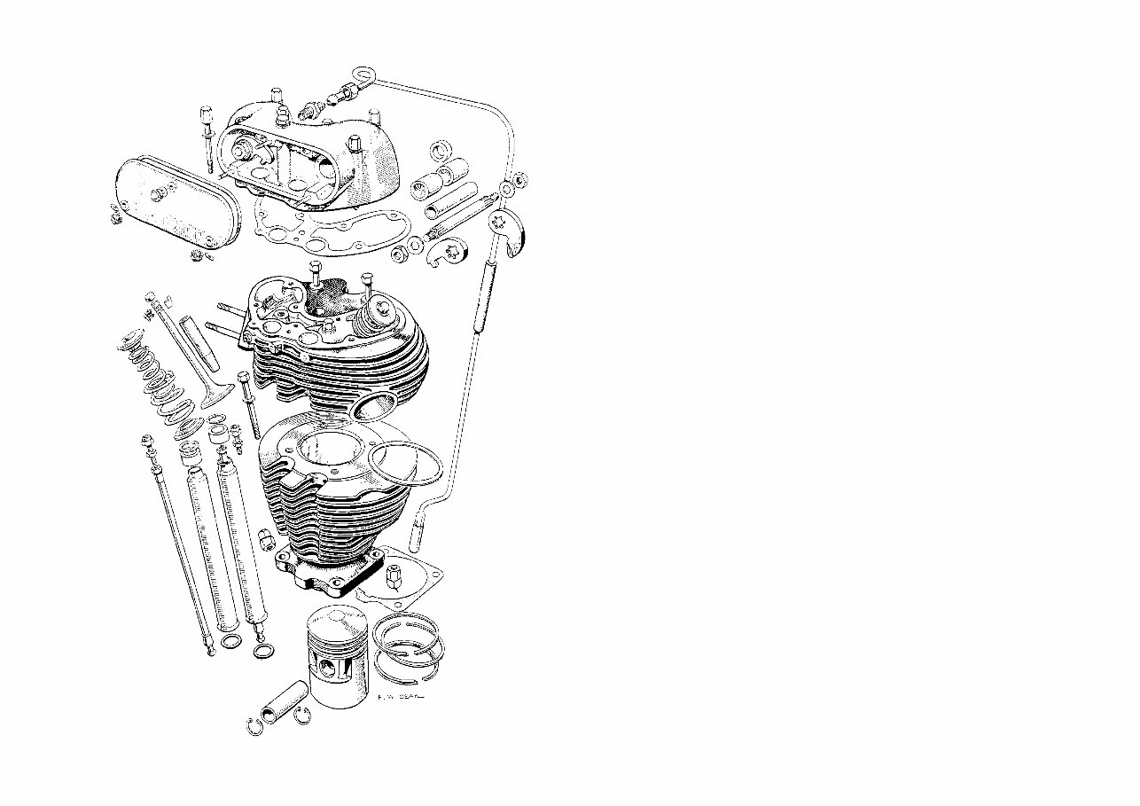
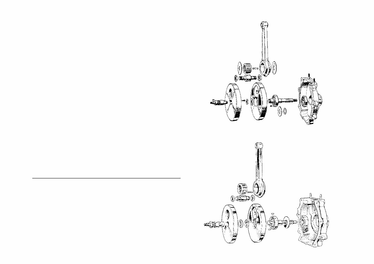
DECARBONIZING THE ENGINE grinding must be avoided, particularly as the valve seats in light-alloy heads are not replaceable. After valve grinding, wash the head and valves in petrol, check oil passages in the valve guides and ensure that all trace of grinding paste is removed. Pass a piece of non-fluffy rag through each valve guide in turn, one way only, and then squirt clean oil through passages in the head for guide lubrication. Check the valve springs for free length. If the free length has decreased x-in. or more, fit new springs. Oil both valve stems and reassemble with springs, taking care that both collets are correctly located in the two grooves on the valve stem. To check if the valves are seating correctly, wipe off oil from both valve heads and the sphere of the cylinder head. Hold the head with the exhaust port vertical and nearly fill the port with petrol. If after a few minutes petrol does not seep past the valve, the seating is in order. Empty out the petrol, and if petrol is spilled into the sphere of the head wipe it dry and repeat the test for the inlet valve, after which the head can be put aside. Set the piston on the top of its stroke, carefully scrape off carbon formed on the piston crown, using the recommended tool. The ridge of carbon formed in the cylinder barrel should also be removed. Afford a little time in which to remove the particles of carbon trapped in the gap formed by the top land of the piston and cylinder wall. If the cylinder is removed to examine piston rings for gas leakage, do not remove the rings unless it is necessary. Gas leakage is indicated by black or brown portions on the ring bearing face. Renew the cylinder-base gasket before refitting the cylinder. Reassembly The use of new gaskets is most desirable if one is to avoid again taking down the engine after reassembly in order to rectify oil leaks and a leaking cylinder-head joint Cylinder-head gaskets of the solid-copper type can be used again if not distorted or showing ovality in the bolt holes, by heating them until cherry red and then plunging into cold water. This will make the gasket ductile. Renew the two bottom push-rod tube rubbers. Start assembling by: (i) Turning the engine until the piston is on the top of its stroke with both tappets down. (ii) Place new sealing rubber over each tappet. (iii) Pull out and discard the two sealing rubbers for the push-rod tubes in the cylinder head. Watch for the steel washer on top of each rubber; press new rubbers into position, apply a little jointing compound on the top end of each push-rod tube and insert them into the head with a rotary motion, (iv) Clean the threads for the cylinder-head bolts and apply a little graphite grease to facilitate subsequent removal. (v) Put in position the cylinder-head gasket and place the cylinder head and cover tubes into the cylinder barrel. Some care and patience is needed at this stage to verify that the head gasket is located accurately when the head bolts are passed through the cylinder head. Lift the head slightly and see if the bolts go through the four gasket holes correctly, then tighten down the head bolts diagonally until all four are firmly tightened. If a Top-half components of the Matchless WD-G3L circa 1941 MATCHLESS SINGLES 1939 -1955 FIG 1 4 www.ajs-matchless.info
torque spanner is available, set it to 36 Ib.ft. Note: On early models the space between the carburetter air intake and oil tank is restricted; it is therefore preferable to fit the carburetter to the cylinder head before refitting the head and after dealing with the carburetter as detailed later. Oil both push-rod ends before placing them in the push-rod tubes. A new rocker-box gasket must be used, and this can now be placed on the cylinder head. On engines made before 1949 there is a projection on the gasket with a hole in it which must register with the oil-feed hole in the cylinder head lubricating the inlet-valve guide. Refit the two valve end caps (on engines before 1949). Clean both faces of the rocker box; fit the centre rocker-box bolts first, put the rocker box into position, tilt it and engage the push-rods with the two rocker arms, tighten lightly the centre bolts, fit the remaining bolts and tighten all down evenly and diagonally. Remember that a soft gasket is used and exercise care by not over-tightening these bolts, which may stretch or break if undue force is used. Both valves must be closed when rocker-box bolts are tightened, and with the engine in this position adjust push-rods so that there is no noticeable up-and-down movement with free rotation. For engines with iron cylinder heads this adjustment is made with the engine cold. The petrol tank may be replaced temporarily so that the engine can be run for a short period to settle the valve gear when a final adjustment can be made after the engine has cooled down. On engines with alloy heads make this adjustment with the engine reasonably warm. Finally, before fitting the petrol tank and the rest of the parts removed, adjust the throttle and air cables to take up slack; neatly arrange these cables, the H.T. wire and lighting harness, which should be attached to the frame top tube with clips or adhesive tape. Avoid over-tightening the petrol-tank fixing bolts and secure these with copper wire run through holes in tank bolts, thus joining front and rear bolts in pairs. 2. SERVICING ENGINES Heavy Oil Consumption If the machine has covered considerable mileage with a gradual increase in oil consumption, the cause can be due to worn or broken piston rings, cylinder wear, or a combination of both. The normal ring gap is 0.006 in. with a permissible maximum of 0.030 in. The ring clearance in its groove is 0.002 in. Should cylinder wear exceed 0.008 in., the cylinder should be rebored and a suitable oversize piston used. When fitting new piston rings a chromium-plated compression ring for the top ring groove should be used, since this will minimize cylinder wear. These rings, when new, have a slightly tapered exterior and are marked with the word TOP on one side to indicate assembly positron. 5 DECARBONIZING THE ENGINE / SERVICING ENGINES Bottom-half crankshafts with drive-side crankcase. (Above) For 1945-1954 models, (Below) For 1955-on MATCHLESS SINGLES 1939 -1955 FIG 3 FIG 2 www.ajs-matchless.info
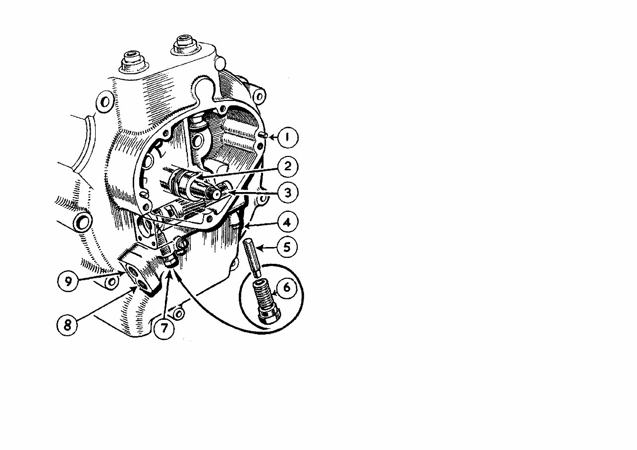
FIG 4 Inset is the fixed guide screw which engages in the scroll grooved in the plunger body whereby reciprocating action is added to the rotation of the plunger 1. Dowel peg, locating timing-gear cover 2. Timing-side flywheel axle with integral gear for driving oil-pump plunger 3. Oil-pump plunger 4. Screw (one of three) 5. Guide pin 6. Screwed body for guide pin 7. Guide pin in position engaged in profiled cam groove of plunger 8. Tapped hole (for oil-feed pipe to pump) 9. Tapped hole (for pipe returning oil to oil tank) MATCHLESS SINGLES 1939 -1955 An incorrectly set oil-regulating screw, which controls oil supply to inlet valve, can affect oil consumption. The correct position for this screw is half a turn open from the fully-closed position. Worn valve guides will allow oil to enter the combustion chamber. Evidence of an excessive amount of oil in the valve-spring chambers can be due to oil building up in the push-rod cover tubes on early-type engines. The use of a later-type tappet guide with six slots, described in Chapter 3, "Overhauling the Egine," will enable oil to drain into the timing chest more freely. Excessive Smoke on Starting The cause can be due to the details given for heavy oil consumption, or excessive oil in the crankcase due to bad scavenging; alternatively, oil seeps into the crankcase when the engine is stationary. Bad scavenging can be caused by an air leak between the cap covering the rear end of the pump housing or obstruction in the oil passage from the sump to the pump. In the event of oil seepage, this is usually due to a worn or scored pump-plunger housing in the crankcase. To decide if seepage occurs, use a dipstick to measure the oil level in the tank, then check the oil level again after the machine has been standing overnight If the level has fallen the timing-side crankcase should be sent to the manufacturer for examination and possibility of bushing the pump plunger bore. Restriction in the oil-tank filter will affect the oil return from the sump, Oil Pump Plunger This part of the engine should not be disturbed unless the crankcase is dismantled or the oiling system becomes defective. The small hexagon bolt housing the pump-guide pin, situated at the rear end of the plunger housing, is often mistaken for a drain plug. If this bolt is unscrewed, either intentionally or unintentionally, the pump plunger will be damaged beyond further use when the bolt is tightened if the guide pin is not correctly located in the groove machined in the plunger. To ensure correct location the cap at the rear end of the plunger housing should first be removed. If a short piece of spoke or stiff wire is inserted into the hole drilled in the plunger, this can be moved slightly inwards and outwards during the process of screwing home the pump-guide pin bolt by hand, and finally tightening it with a spanner when correct location is effected. Excessive tooth wear in one particular position indicates a restriction in the feed line. This can be due to a blocked oil passage in the timing-side axle, the crankpin or an obstruction in the rocker-box oil-feed line. Slight uniform tooth marking is normal on engines that have covered a considerable mileage. If the pump plunger is damaged after an engine overhaul, the timing-side axle or crankpin are incorrectly located (see Chapter 3, "Overhauling the Engine"). If all the teeth are badly damaged the main-bearing spacing washer may be worn ( see the section on "Flywheel Assembly.") Rocker Box Oil Supply If the oil supply to this part of the engine is gradually reduced or stops entirely, wear at the end of the pump guide pin has developed and a new pin should be used. SERVICING ENGINES 6 www.ajs-matchless.info
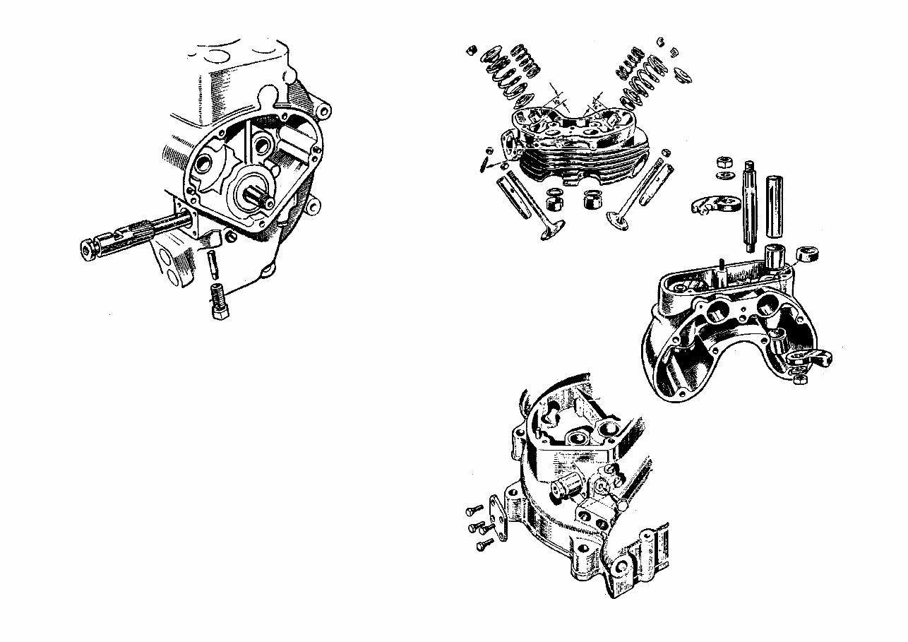
SERVICING ENGINES FIG 5 Correct assembly of the off pump. The spiral groove at the end of the pump plunger must mesh with stationary peg shown at the bottom of the sketch; the plunger should both rotate and reciprocate when the engine is turned by hand An incorrectly located paper gasket used between the front pump end-cap and crankcase will also stop the oil supply. Crankcase Release Valve This valve will be found on the driving-side crankcase, behind the primary chaincase, and has a short copper pipe attached to it. The valve is a steel disc or diaphragm, retained in the valve body, which has a serrated seat; the disc moves towards the serrated seat as the piston descends, allowing pressure in the crankcase to escape into the atmosphere. If the disc is trapped between the valve body and the crankcase it will not operate and will cause oil leakage from engine joints. It will also cause oil to accumulate in the push-rod cover tubes and cause the engine to smoke badly. If this valve is dismantled, place a little grease on the serrated seat to retain the disc in position whilst the valve is refitted* Oil Leaks First ascertain the exact position of leakage as oil can run down the back of the push-rod cover tubes and give the impression that the leak occurs at the cylinder-base joint. Oil leakage at the cylinder base can only be due to loose cylinder nuts or a damaged paper gasket provided that the crankcase face is not bruised or otherwise damaged. 7 MATCHLESS SINGLES 1939 -1955 The oilways in the valve guides and in the head must align Part-disassembled arrangement of the Matchless oil pump FIG 7 FIG 6 FIG 8 www.ajs-matchless.info
Defective rubber sealing rings at the top and bottom of the push-rod cover tubes will cause oil leakage. If the cover tubes can be moved, there is insufficient pressure on the oil seals. To remedy, fit a 3 / 64 -in. steel washer on the reduced end of the cover tubes below the top sealing rubbers in the cylinder head. An oil leak from the metal cap in the timing cover can be cured only by fitting a new cap. Pierce a hole in the cap and prise it out, wash the aperture with petrol, apply jointing compound on the outside rim of the cap and tap it into position. Let the jointing compound set before starting the engine. Exhaust Valve Seizure or Sluggishness The symptoms of this trouble are misfiring — the engine cuts out with a sudden increase in push-rod noise, usually after driving fast or after climbing a gradient. Engines with light-alloy heads are not usually affected with this trouble as the cylinder-head temperature is lower under normal driving conditions. A heavy formation of carbon or burnt oil on the exhaust-valve stem and in the guide bore causes the valve to become sluggish and possibly to seize when the engine temperature increases. To remedy, the head must be removed from the cylinder so that all carbon or burnt oil deposited on the valve stem and its guide can be removed ( see Chapter 1, "Decarbonizing the Engine"). Reducing the oil supply will prevent a repetition, which can be effected by inserting a short piece of x-in. outside diameter tube into the hole in the rocker box, which feeds oil by gravity to the exhaust valve. The tube should protrude x-in. to ¼-in. above the rocker-box case. As an alternative, a copper or aluminium plug with a small flat filed on it can be inserted into the oil hole in the cylinder head, which registers with the exhaust-valve oil-feed hole in the rocker box. Hairpin Valve Spring and Collar Wear Engines made from 1949 up to 1953 are most likely to be affected by this kind of wear and then usually the inlet spring only shows signs of it. This can be prevented by increasing the oil supply to the inlet-valve rocker arm. To modify, enlarge the oil hole drilled in the boss for the rocker axle to x-in. Obtain a metering plug from the manufacturer, Part No. 018890, and insert this into the enlarged hole. This plug has a small hole at one end; insert this end first and tap the plug home. A further light tap with a centre punch will prevent the plug from moving. This adjustment reduces the oil supply to the exhaust valve, which is already generous, and increases the oil feed to the inlet rocker. Later-type rocker arms, valve end only, have a groove machined on the face of each rocker to convey oil to the valve end and valve-spring collar. Wear on Valve Ends and Rockers Wear on the valve-stem tips will certainly take place if engines made before 1949 are used without the hardened valve end-caps. Engines made from 1949 are fitted with heat-treated valve-stem tips and are of a different overall length {see Tables). If the wear is slight the valve, after removal, can be turned 90° to its original position, as wear by contact with the rocker forms a groove across the valve end. A permanent cure is to grind Q-in. off the valve end and employ the hardened valve-end caps used on earlier-type engines. The oil modification to the rocker box should be included if the engine is made before 1954. If the rocker is slightly worn it can be stoned, otherwise replaced. VALVE LENGTH Model 1946-48 1946-48 1949-57 1949-57 cc 350 500 350 500 Inlet Exhaust 4 z-in. 3 ,-in. 4 x-in. 4 z-in. Valve Guides All types are a force fit in the cylinder head and the guide protrusion away from the port is of paramount importance. (See overleaf.) They are made from chilled cast iron, are hard and somewhat brittle, therefore care to avoid breaking the guide during the process of removal or refitting is most necessary. To remove guides on iron cylinder heads, clean off burnt oil from the guide, where it protrudes above the port, with emery cloth. With the head supported on a bench, use a suitable drift to drive out the guide, or use a hand press if available. When dealing with alloy heads, the head must be heated before attempting to remove a guide, otherwise damage by enlargement of the guide bore will take place. First ascertain if a circlip is fitted to the exhaust guide; this is a standard fitting in all models after 1955. If a circlip is fitted, heat the head, tap the guide up through the port so that the circlip can be prised out of its groove. Reheat the head and follow the instructions given for iron heads. Refitting Valve Guides To ensure that the guide starts parallel with the guide bore, insert the valve into the head, press the valve firmly on to its seat. Retaining the pressure, place the guide over the valve and ensure that the oil hole is properly aligned; then press the guide down as far as possible and, finally, tap the guide home to the specified protrusion. Loose Valve Guide Removing the exhaust-valve guide on alloy cylinder heads without pre-heating is usually the cause of this trouble. As a new head is expensive, a satisfactory repair can be made by copper plating the external diameter of the guide to the extent of 0.003 in. to 0.004 in. to close up the interference fit. Use a guide machined for a circlip, together with a later-type valve-spring seat. If a radius is ground on the valve-spring seat to clear the circlip, the original seat can be retained. MATCHLESS SINGLES 1939 -1955 8 SERVICING ENGINES www.ajs-matchless.info
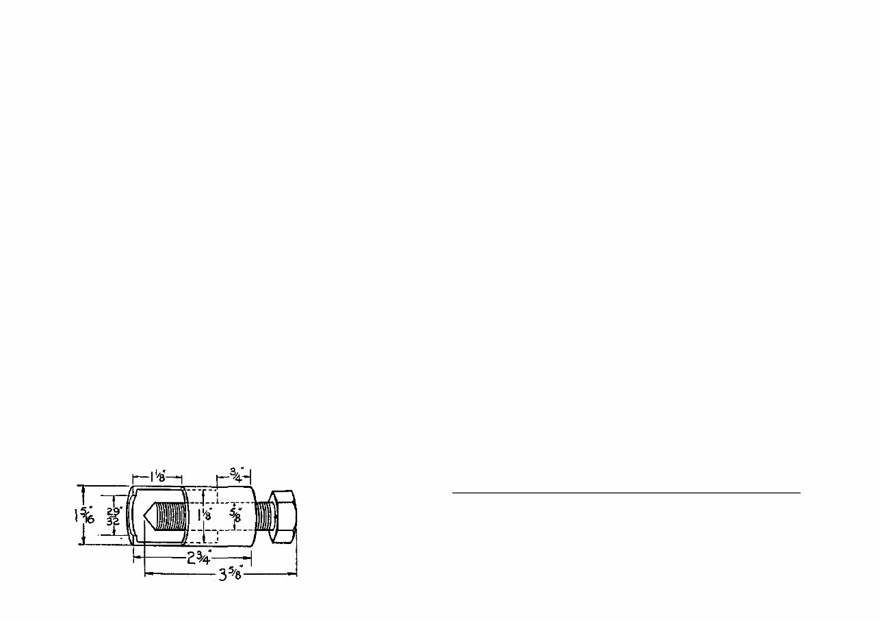
Valve Guide Protrusion Before 1948. Inlet-valve guide, ½-in.; exhaust-valve guide, s-in. After 1948. Inlet-valve guide, ½-in.; exhaust-valve guide, ½-in. Camshaft Wear If the peak of either cam is bruised or badly worn, look for overloading on the valve-operating gear. The usual reason is that the valve springs are coil-bound when the valve is at full lift (coil-type springs) or the valve-guide protrusion is incorrect, causing the spring collar to foul the guide* To check valve motion, turn the engine until the valve is at maximum lift. Place a box key on the nut retaining the push-rod rocker arm and endeavour to open the valve further; if further movement cannot be made the valve springs are solid or coil-bound and should be exchanged for a set of the correct type. If the cams are badly damaged, check also both tappets for wear and see Chapter 3, "Overhauling the Engine," for removal drill. Piston Slap Engine noises of various kinds are often attributed to piston slap, which is caused only by excessive clearance between the piston and the cylinder Piston slap is audible when the engine is pulling, or on changing up to a higher gear, but not when the engine is running light or without load. Reboring the cylinder and using an oversize piston is the only remedy for a noise of this kind. The wire-wound piston which has been used for some time permits the use of a close running clearance of 0,001 in. with a reduced risk of piston seizure. Engines made before 1947 can use this type of piston if the connecting rod is exchanged for a later type, as there is a difference of ½ - in, in the two connecting-rod lengths. The small-end bush is not usually affected by premature or undue wear; therefore piston slap should not be confused with a slack small-end bearing. Big-End Noise If a light rattle develops, which becomes inaudible when the engine is pulling or under load, a little movement in the big-end assembly is usually the cause. This does not indicate that the bearing is completely worn out, for it is often possible to cover a further 8,000 to 10,000 miles without effect on the engine efficiency. This noise can develop when there is an accumulated clearance between 0,0015 in. and 0,002 in. in the big-end assembly. It is possible that a new set of rollers will absorb movement; alternatively, fit rollers plus 0.001 in. oversize after lapping the connecting rod {see Chapter 3, ''Overhauling the Engine"), provided the roller path on the crankpin and liner are undamaged. Timing Gear Noise This noise can develop when there is (a) an accumulated clearance between the camwheels and small timing pinion, (b) end-float between the cam which drives the magneto and the crankcase, and (c) wear on the bushes for the cams or a worn timing-shaft bush, which would affect teeth engagement on the timing gear. First check for end-float by removing the magneto chain cover, run the engine to develop the noise and press on the end of the shaft that drives the lower magneto sprocket with a piece of wood or screwdriver handle. If the noise stops there is end-float, which is cured by removing the magneto drive and the timing-gear cover and fitting a shim washer either 0.005 in. or 0.010 in. thick over the shaft for the cam wheel before refitting the timing-gear cover. Backlash can be verified by reproducing the noise and applying pressure on the top run of the magneto driving chain with a wooden screwdriver handle. If the noise stops, try first a new small timing pinion before replacing the cam wheels. If the noise persists, check for worn bushes. Noise in the Rocker Box A little end-float in the rocker axles is of no consequence. This movement can be taken up by tapping outwards one of the two bushes after removing the rocker arm, axle and sleeve. The rockers should move freely if the bushes are correctly located. A distorted hairpin-type valve spring may make contact with the rocker box. Reversing the position of the spring may have the desired effect Look also for a groove on the valve spring at the point where the rocker operates — this can also cause a noise. A slight radius ground on the rocker arm at the position of contact will prevent a recurrence. If the spring is badly grooved it should be discarded. 9 MATCHLESS SINGLES 1939 -1955 3. OVERHAULING THE ENGINE Provided workshop facilities, together with an adequate supply of box keys and spanners are available, no great difficulty should be experienced in dealing with work of this kind, Some thought on preparation for overhauling is desirable by having available such items as an extractor tool for the dynamo sprocket, a small timing pinion extractor, a spare parts list, a complete gasket set, jointing compound, preferably Details of one of the few special tools, a main-shaft timing pinion extractor, suggested by the makers FIG 9 SERVICING ENGINES / OVERHAULING THE ENGINE www.ajs-matchless.info
This Matchless 1939-1955 Workshop Service Manual for Repair provides comprehensive data, characteristics, instructions, and methodology for performing repair interventions on the vehicle and its components. It includes special notes, important points, service data, precautions, and detailed illustrations, exploded diagrams, drawings, and photos to guide you through every service repair procedure. This manual is intended as a handy, easy-to-read reference book for both professional mechanics and DIY enthusiasts.
The most detailed, comprehensive step-by-step procedures, explanations, and pictorial diagrams from bumper to bumper are included. Adjustment and repair operations reference service tool numbers, and the associated illustration depicts the tool for Matchless 1939-1955. The manual can be viewed on any computer, zoomed, and printed. It has been specially prepared so that even comparatively new personnel can give satisfactory after-services to the customers as well as disassemble and maintain the vehicle.
All service and repair instructions are included, and it provides general descriptions for accomplishing service and repair work with tested, effective techniques. The manual outlines procedures for servicing and repairing vehicles using safe, effective methods, and contains many notes, cautions, and warnings which should be followed along with standard safety procedures to eliminate the possibility of personal injury or improper service which could damage the vehicle or compromise its safety.
To maximize the life of your Matchless 1939-1955, it is important to accurately follow the maintenance requirements, investigate unusual noises and changes in riding characteristics, use only genuine parts, follow the procedures in the manual carefully, keep complete records of all maintenance and repairs, and use only approved lubricants as specified in the manual.
This manual is designed primarily for use by trained technicians in a properly equipped workshop, but it contains enough detail and basic information to make it useful to the owner who desires to perform basic maintenance and repair work. A basic knowledge of mechanics, including the proper use of tools and workshop procedures, is necessary in order to carry out maintenance and repair work satisfactorily.
For all maintenance and repair work on Matchless 1939-1955, all accident prevention guidelines must be strictly observed. No special emphasis is put on replacing sealing components as it is assumed that these items are replaced during any repair. Unless specific values are given, all threaded connections should be tightened according to the required tightening torques listed on torque charts.
This Matchless 1939-1955 Workshop Service Manual for Repair is a quality manual that is 100% complete and intact, with no missing/corrupt pages/sections. It is known by many names including service manual, repair manual, workshop manual, and shop manual. The manual provides technical information regarding the design, function, disassembly, adjusting work, and troubleshooting on the components and model of the Matchless 1939-1955.
It is supported by photographs, notes, drawings, schematics, as well as exploded and sectional drawings, and contains information about adjusting work and valuable reference data for such adjustment values. All accident prevention guidelines must be strictly observed, and to perform all repairs listed in this manual, a complete set of standard tools, as well as the special tools and fixtures shown and listed, are necessary.
When describing work which can be dangerous, the required safety measures are described in the manual and indicated by special remarks DANGER, CAUTION, or NOTE. The manual also includes specifications, vehicle identification number (V.I.N.), wheels, tires, brakes, fenders, steering, engine, lubrication system, ignition system, charging system, lighting system, and more.