Kymco Xciting 250 Scooter Factory Service & Work Shop Manual
What's Included?
Lifetime Access
Fast Download Speeds
Online & Offline Access
Access PDF Contents & Bookmarks
Full Search Facility
Print one or all pages of your manual
XCITING 500/250
XCITING 500/250 PREFACE This Service Manual describes the technical features and servicing procedures for the KYMCO XCITING 500/250. Section 1 contains the precautions for all operations stated in this manual. Read them carefully before any operation is started. Section 2 is the removal/installation procedures for the frame covers which are subject to higher removal/installation frequency during maintenance and servicing operations. Section 3 describes the inspection/ adjustment procedures, safety rules and service information for each part, starting from periodic maintenance. Sections 7 through 13 give instructions for disassembly, assembly and adjustment of engine parts. Section 14 through 16 is the removal/ installation of chassis. Section 17 through 21 states the testing and measuring methods of electrical equipment. Most sections start with an assembly or system illustration and troubleshooting for the section. The subsequent pages give detailed procedures for the section. KWANG YANG MOTOR CO., LTD. OVERSEAS SALES DEPARTMENT OVERSEAS SERVICE SECTION TABLE OF CONTENTS GENERAL INFORMATION 1 FRAME COVERS /EXHAUST MUFFLER 2 INSPECTION/ADJUSTMENT 3 LUBRICATION SYSTEM 4 FUEL SYSTEM/FUEL PUMP/FUEL TANK/CARBURETOR 5 COOLING SYSTEM 6 ENGINE REMOVAL/INSTALLATION 7 CYLINDER HEAD/VALVES 8 CYLINDER/PISTON 9 DRIVE AND DRIVEN PULLEY 10 FINAL REDUCTION 11 A.C. GENEARTOR/STARTER CLUTCH 12 CRANKCASE/CRANKSHAFT 13 STEERING HANDLEBAR/FRONT WHEEL/FRONT SHOCK ABSORBER 14 REAR FORK/REAR WHEEL/REAR SHOCK ABSORBER` 15 BRAKE SYSTEM 16 BATTERY/CHARGING SYSTEM 17 IGNITION SYSTEM 18 ELECTRIC STARTER 19 LIGHTS/METERS/SWITCHES 20 WIRING DIAGRAMS 21 The information and contents included in this manual may be different from the motorcycle in case specifications are changed. KYMCO reserves the right to make changes at any time without notice and without incurring any obligation. CHASSIS ELECTRICAL EQUIPMENT ENGINE
1. GENERAL INFORMATION 1-0 XCITING 500/250 __________________________________________________________________________________ __________________________________________________________________________________ __________________________________________________________________________________ __________________________________________________________________________________ __________________________________________________________________________________ GENERAL INFORMATION __________________________________________________________________________________ SERIAL NUMBER----------------------------------------------------------- 1 - 1 SPECIFICATIONS (XCITING 500)--------------------------------------- 1 - 2 SPECIFICATIONS (XCITING 250)--------------------------------------- 1 - 3 SERVICE PRECAUTIONS ------------------------------------------------- 1 - 4 TORQUE VALUES ---------------------------------------------------------- 1 - 8 SPECIAL TOOLS ------------------------------------------------------------ 1-12 LUBRICATION POINTS --------------------------------------------------- 1-13 CABLE & HARNESS ROUTING (XCITING 500) ------------------------- 1-15 CABLE & HARNESS ROUTING (XCITING 250) ------------------------- 1-25 TROUBLESHOOTING------------------------------------------------------ 1-33 1
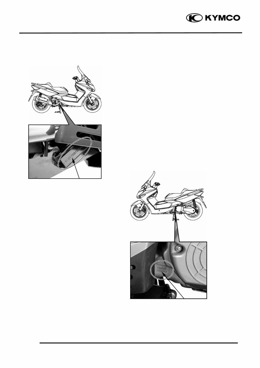
1. GENERAL INFORMATION 1-1 XCITING 500/250 SERIAL NUMBER Location of Engine Serial Number Location of Frame Serial Number
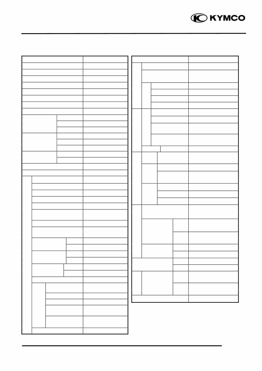
1. GENERAL INFORMATION 1-2 XCITING 500/250 SPECIFICATIONS (XCITING 500) ITEM SPECIFICATIONS Name XCITING 500 Overall length 2250 mm (90 in) Overall width 815 mm (33 in) Overall height 1450 mm (58 in) Wheel base 1570 mm (63 in) Engine type O.H.C. Displacement 498.5 cm 3 (30.4 cu-in) Fuel Used 92# nonleaded gasoline Front wheel 83 kg (183 lbs) Dry weight Rear wheel 132 kg (290 lbs) Total 215 kg (473 lbs) Front wheel 90 kg (198 lbs) Curb weight Rear wheel 141 kg (310 lbs) Total 231 kg (508 lbs) Front wheel 120/70-15 Rear wheel 150/70-14 Ground clearance 150 mm (6 in) Min. turning radius 2750 mm (110 in) Starting system Electric starter motor Type Gasoline, 4-stroke Cylinder arrangement Single cylinder Combustion chamber type Semi-sphere Valve arrangement O.H.C., chain drive Bore x stroke 92 x 75 mm (3.7 x 3 in) Compression ratio 10.5:1 Compression pressure 13 kgf/cm² (1300kPa, 185 psi) Open 2° BTDC Intake valve Close 45° ABDC Open 45° BBDC Exhaust valve Close 5° ATDC Valve clearance Intake 0.1 mm (0.004 in) (cold) Exhaust 0.1 mm (0.004 in) Idle speed 1400 rpm Lubrication type Forced pressure & Wet sump Oil pump type Trochoid Oil filter type Full-flow filtration Oil capacity 2.5 L (2.2 lmp qt, 2.65 Us qt) Final reduction oil capacity 0.55 L (0.5 lmp qt, 0.58 Us qt) Cooling Type Liquid cooled ITEM SPECIFICATIONS Air cleaner type & No Wet paper type element Fuel capacity 12.8 L (3.38 lmp gal, 2.82 US gal Type CVK Main jet NO. 98 Venturi dia. φ36 mm (φ1.44 in) Throttle type PISTON Type Full transistor ignition Spark plug CR8E Ignition timing Throttle position sensor Spark plug gap 0.6~0.7mm (0.002~ 0.003 in) Battery Capacity 12V12AH Clutch Type Dry, centrifugal automatic Type Helical gear/spur gear Operation Automatic centrifugal Type Type CVT Preliminary 2.68 – 1 Final 5.4 FR/RR tire rolling circumference 1724/1778 mm (69/71 in) Front 2 kg/cm² (200 Kpa, 28 psi) Tire pressure (rider only/60 kg) Rear 2.5 kg/cm² (250 Kpa, 36 psi) Turning Left 40° angle Right 40° Brake system Rear Disk brake type Front Disk brake Front Telescopic fork Suspension type Rear Unit swing Frame type Back born Tires Fuel System Carburetor Electrical Equipment Ignition System Power Drive System Transmis- sion Gear Reduction Ratio Moving Device Damping Device Lubrication System Engine
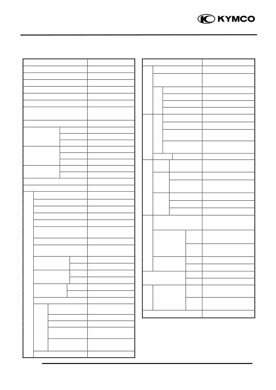
1. GENERAL INFORMATION 1-3 XCITING 500/250 SPECIFICATIONS (XCITING 250) ITEM SPECIFICATIONS Name XCITING 250 Overall length 2250 mm (90 in) Overall width 815 mm (33 in) Overall height 1450 mm (58 in) Wheel base 1570 mm (63 in) Engine type O.H.C. Displacement 251/249.1 cm 3 (15.3/15.8 cu-in) Fuel Used 92# nonleaded gasoline Front wheel 75 kg (165 lbs) Dry weight Rear wheel 110 kg (242 lbs) Total 185 kg (407 lbs) Front wheel 81 kg (178 lbs) Curb weight Rear wheel 119 kg (262 lbs) Total 200 kg (440 lbs) Front wheel 120/70-15 Rear wheel 150/70-14 Ground clearance 170 mm (6.8 in) Min. turning radius 2600 mm (104 in) Starting system Electric starter motor Type Gasoline, 4-stroke Cylinder arrangement Single cylinder Combustion chamber type Semi-sphere Valve arrangement O.H.C., chain drive Bore x stroke 72.7 x 60 mm (2.908 x 2.4 in) Compression ratio 10.3:1 Compression pressure 15 kgf/cm² (1500kPa, 213 psi) Open 9° BTDC Intake valve Close 45° ABDC Open 38° BBDC Exhaust valve Close 10° ATDC Valve clearance Intake 0.1 mm (0.004 in) (cold) Exhaust 0.1 mm (0.004 in) Idle speed 1600 rpm Lubrication type Forced pressure & Wet sump Oil pump type Trochoid Oil filter type Full-flow filtration Oil capacity 1.1 L (0.97 lmp qt, 1.17 Us qt) Final reduction oil capacity 0.2 L (0.18 lmp qt, 0.21 Us qt) Cooling Type Liquid cooled ITEM SPECIFICATIONS Air cleaner type & No Wet paper type element Fuel capacity 12.8 L (3.38 lmp gal, 2.82 US gal Type CVK Main jet NO. 94 Venturi dia. φ30 mm (φ1.2 in) Throttle type PISTON Type Full transistor ignition Spark plug DPR7EA-9 Ignition timing Throttle position sensor Spark plug gap 0.6~0.7mm (0.002~ 0.003 in) Battery Capacity 12V12AH Clutch Type Dry, centrifugal automatic Type Helical gear/spur gear Operation Automatic centrifugal Type Type CVT Preliminary 0.83 – 2.2 Final 8.72 FR/RR tire rolling circumference 1724/1778 mm (69/71 in) Front 2 kg/cm² (200 Kpa, 28 psi) Tire pressure (rider only/60 kg) Rear 2.5 kg/cm² (250 Kpa, 36 psi) Turning Left 40° angle Right 40° Brake system Rear Disk brake type Front Disk brake Front Telescopic fork Suspension type Rear Unit swing Frame type Back born Tires Fuel System Carburetor Electrical Equipment Ignition System Power Drive System Transmis- sion Gear Reduction Ratio Moving Device Damping Device Lubrication System Engine
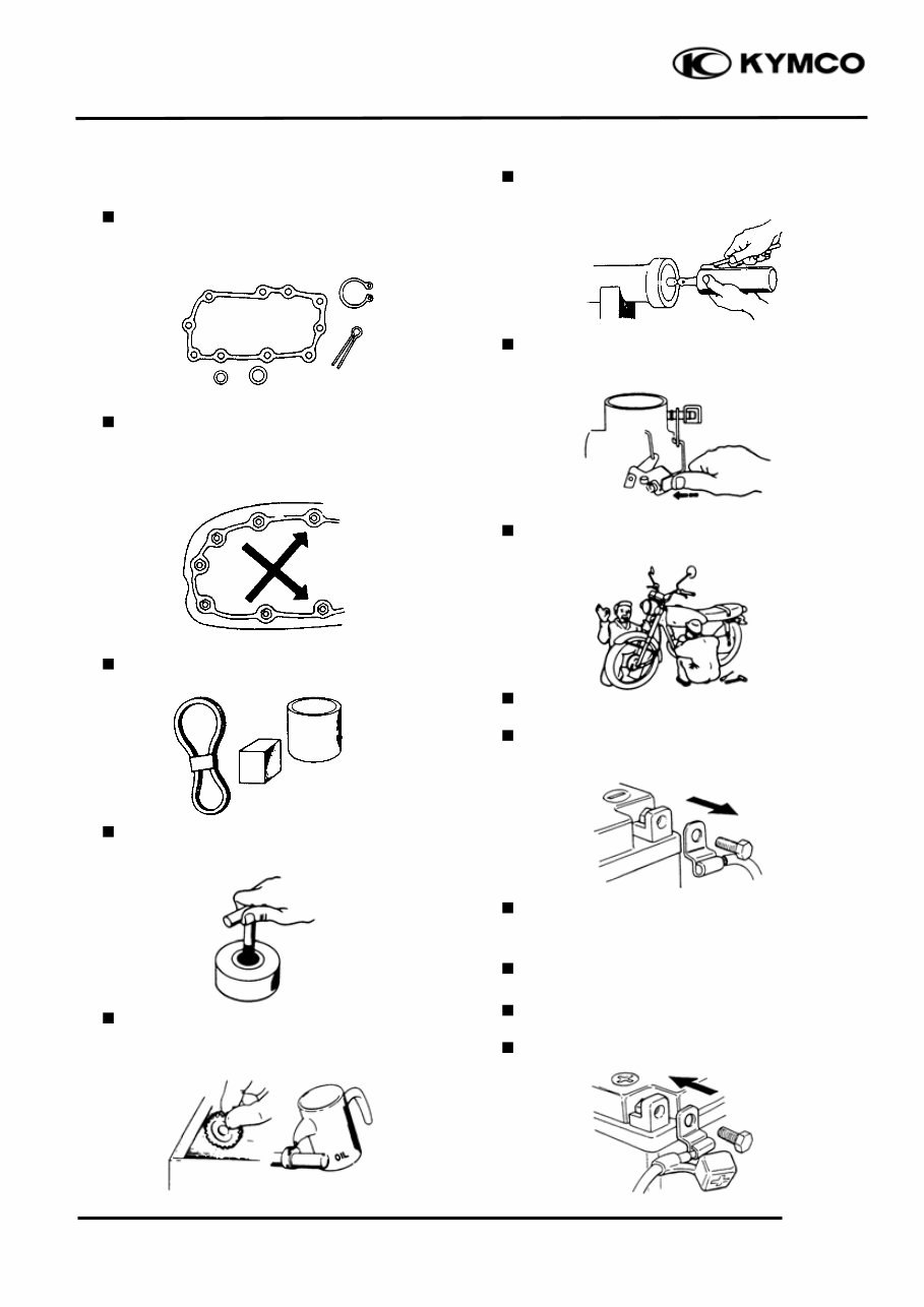
1. GENERAL INFORMATION 1-4 XCITING 500/250 SERVICE PRECAUTIONS Make sure to install new gaskets, O-rings, circlips, cotter pins, etc. when reassembling. When tightening bolts or nuts, begin with larger-diameter to smaller ones at several times, and tighten to the specified torque diagonally. Use genuine parts and lubricants. When servicing the motorcycle, be sure to use special tools for removal and installation. After disassembly, clean removed parts. Lubricate sliding surfaces with engine oil before reassembly. Apply or add designated greases and lubricants to the specified lubrication points. After reassembly, check all parts for proper tightening and operation. When two persons work together, pay attention to the mutual working safety. Disconnect the battery negative (-) terminal before operation. When using a spanner or other tools, make sure not to damage the motorcycle surface. After operation, check all connecting points, fasteners, and lines for proper connection and installation. When connecting the battery, the positive (+) terminal must be connected first. After connection, apply grease to the battery terminals. Terminal caps shall be installed securely.
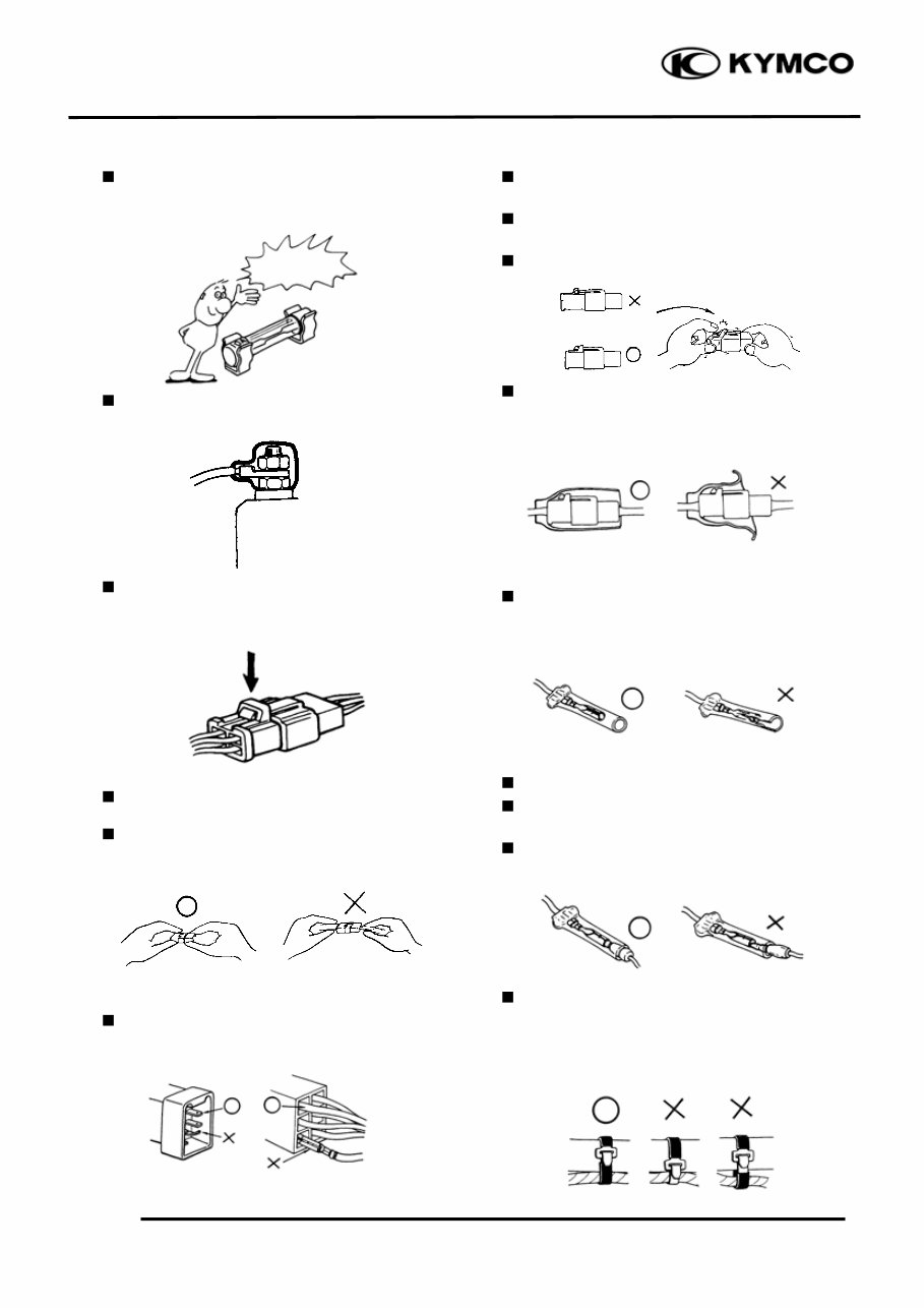
1. GENERAL INFORMATION 1-5 XCITING 500/250 If the fuse is burned out, find the cause and repair it. Replace it with a new one according to the specified capacity. After operation, terminal caps shall be installed securely. When taking out the connector, the lock on the connector shall be released before operation. Hold the connector body when connecting or disconnecting it. Do not pull the connector wire. Check if any connector terminal is bending, protruding or loose. The connector shall be inserted completely. If the double connector has a lock, lock it at the correct position. Check if there is any loose wire. Before connecting a terminal, check for damaged terminal cover or loose negative terminal. Check the double connector cover for proper coverage and installation. Insert the terminal completely. Check the terminal cover for proper coverage. Do not make the terminal cover opening face up. Secure wire harnesses to the frame with their respective wire bands at the designated locations. Tighten the bands so that only the insulated surfaces contact the wire harnesses. Confirm Capacity
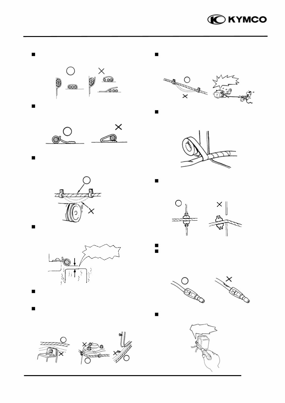
1. GENERAL INFORMATION 1-6 XCITING 500/250 After clamping, check each wire to make sure it is secure. Do not squeeze wires against the weld or its clamp. After clamping, check each harness to make sure that it is not interfering with any moving or sliding parts. When fixing the wire harnesses, do not make it contact the parts which will generate high heat. Route wire harnesses to avoid sharp edges or corners. Avoid the projected ends of bolts and screws. Route wire harnesses passing through the side of bolts and screws. Avoid the projected ends of bolts and screws. Route harnesses so they are neither pulled tight nor have excessive slack. Protect wires and harnesses with electrical tape or tube if they contact a sharp edge or corner. When rubber protecting cover is used to protect the wire harnesses, it shall be installed securely. Do not break the sheath of wire. If a wire or harness is with a broken sheath, repair by wrapping it with protective tape or replace it. When installing other parts, do not press or squeeze the wires. Do not pull too tight! No Contact Do not press or squeeze the i
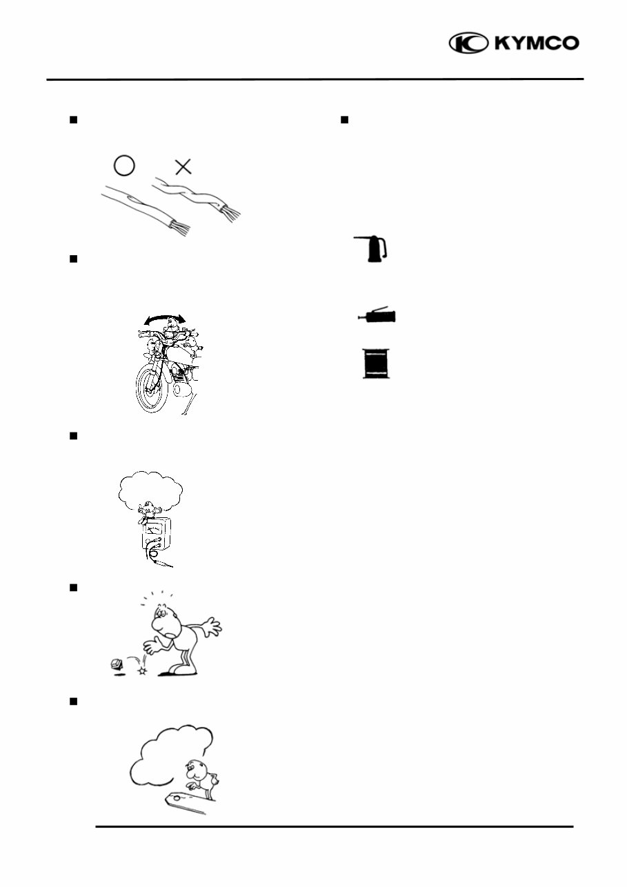
1. GENERAL INFORMATION 1-7 XCITING 500/250 After routing, check that the wire harnesses are not twisted or kinked. Wire harnesses routed along with handlebar should not be pulled tight, have excessive slack or interfere with adjacent or surrounding parts in all steering positions. When a testing device is used, make sure to understand the operating methods thoroughly and operate according to the operating instructions. Be careful not to drop any parts. When rust is found on a terminal, remove the rust with sand paper or equivalent before connecting. Symbols: The following symbols represent the servicing methods and cautions included in this service manual. : Apply engine oil to the specified points. (Use designated engine oil for lubrication.) : Apply grease for lubrication. : Transmission Gear Oil (90#) : Note Engine Oil Grease Gear Oil * Do you understand the instrument? Remove Rust!
Upon purchasing this manual, you will receive a .PDF file containing an email contact. After contacting us, you will receive a reply with a link to access the manual for your Kymco Xciting 250 Scooter.
This comprehensive manual covers every aspect of your machine, providing detailed instructions for tasks ranging from an oil change to a transmission swap. With hundreds of pages, it includes numerous illustrations and easy-to-follow text to assist you throughout your repair or maintenance work.
The manual features a search function, allowing you to easily navigate and print the necessary pages. It serves as a Factory Service Repair Manual, offering step-by-step guidance on fundamental maintenance and repair procedures, equipping you with the knowledge that factory-trained technicians possess.
By utilizing the information in this service repair manual, both professional mechanics and DIY enthusiasts can confidently make informed decisions regarding the maintenance and repair of their machine.
Our commitment extends beyond providing a high-quality service manual; we also ensure excellent customer service, guaranteeing your satisfaction.
Recently Viewed
5,521,897Happy Clients
2,594,462eManuals
1,120,453Trusted Sellers
15Years in Business
Price:
Actual Price:
Kymco Xciting 250 Scooter Factory Service & Work Shop Manual