

Kymco People 250 repair service manual
What's Included?
Fast Download Speeds
Online & Offline Access
Access PDF Contents & Bookmarks
Full Search Facility
Print one or all pages of your manual

PEOPLE 250
C 2003 by KWANG YANG Motor Co., Ltd.
First Edition, Mar 2003
All rights reserved. Any reproduction or unauthorized
use without the written permission of KWANG YANG
Motor Co., Ltd.
is expressly prohibited.
4122-LLJ3-S00
Downloaded from www.Manualslib.com manuals search engine

PEOPLE 250
PREFACE
This Service Manual describes the
technical features and servicing
procedures for the KYMCO People 250.
Section 1 contains the precautions for
all operations stated in this manual.
Read them carefully before any
operation is started.
Section 2 is the removal/installation
procedures for the frame covers which
are subject to higher removal/installation
frequency during maintenance and
servicing operations.
Section 3 describes the inspection/
adjustment procedures, safety rules and
service information for each part, starting
from periodic maintenance.
Sections 5 through 13 give instructions
for disassembly, assembly and adjustment
of engine parts. Section 14 is the
removal/ installation of chassis. Section
16 states the testing and measuring
methods of electrical equipment.
Most sections start with an assembly or
system illustration and troubleshooting
for the section. The subsequent pages
give detailed procedures for the section.
KWANG YANG MOTOR CO., LTD.
OVERSEAS SALES DEPARTMENT
OVERSEAS SERVICE SECTION
TABLE OF CONTENTS
GENERAL INFORMATION 1
EXHAUST MUFFLER/FRAME COVERS 2
INSPECTION/ADJUSTMENT 3
LUBRICATION SYSTEM 4
ENGINE REMOVAL/INSTALLATION 5
CYLINDER HEAD/VALVES 6
CYLINDER/PISTON 7
DRIVE AND DRIVEN PULLEYS/V-
BELT
8
FINAL REDUCTION 9
A.C. GENERATOR/STARTER CLUTCH 10
CRANKCASE/CRANKSHAFT 11
COOLING SYSTEM 12
FUEL SYSTEM/CARBURETOR/FUEL
PUMP FUEL TANK
13
STEERING HANDLEBAR/FRONT
WHEEL/FRONT BRAKE/FRONT
SHOCK ABSORBER/FRONT FORK
14
REAR BRAKE/REAR FORK/REAR
WHEEL/REAR SHOCK ABSORBER`
15
BATTERY/CHARGING SYSTEM 16
IGNITION SYSTEM 17
STARTING SYSTEM 18
SWITCHES/HORN/FUEL UNIT /
THERMO-STATIC
SWITCH/TEMPERATURE
GAUGE/INSTRUMENTS/ LIGHTS
19
The information and contents included in
this manual may be different from the
motorcycle in case specifications are
changed.
CHASSIS
EQUIPMENT
ENGINE
Downloaded from www.Manualslib.com manuals search engine

1. GENERAL INFORMATION
1-0
PEOPLE 250
1
__________________________________________________________________________________
__________________________________________________________________________________
__________________________________________________________________________________
__________________________________________________________________________________
__________________________________________________________________________________
GENERAL INFORMATION
__________________________________________________________________________________
SERIAL NUMBER-------------------------------------------------------- 1-1
SPECIFICATION---------------------------------------------------------- 1-2
SERVICE PRECAUTIONS----------------------------------------------- 1-3
TORQUE VALUES------------------------------------------------------- 1-7
SPECIAL TOOLS--------------------------------------------------------- 1-8
LUBRICATION POINTS------------------------------------------------- 1-9
CABLE & HARNESS ROUTING-----------------------------------------1-11
WIRING DIAGRAM-------------------------------------------------------------------1-18
TROUBLESHOOTING --------------------------------------------------1-19
1
Downloaded from www.Manualslib.com manuals search engine
1. GENERAL INFORMATION
1-1
PEOPLE 250
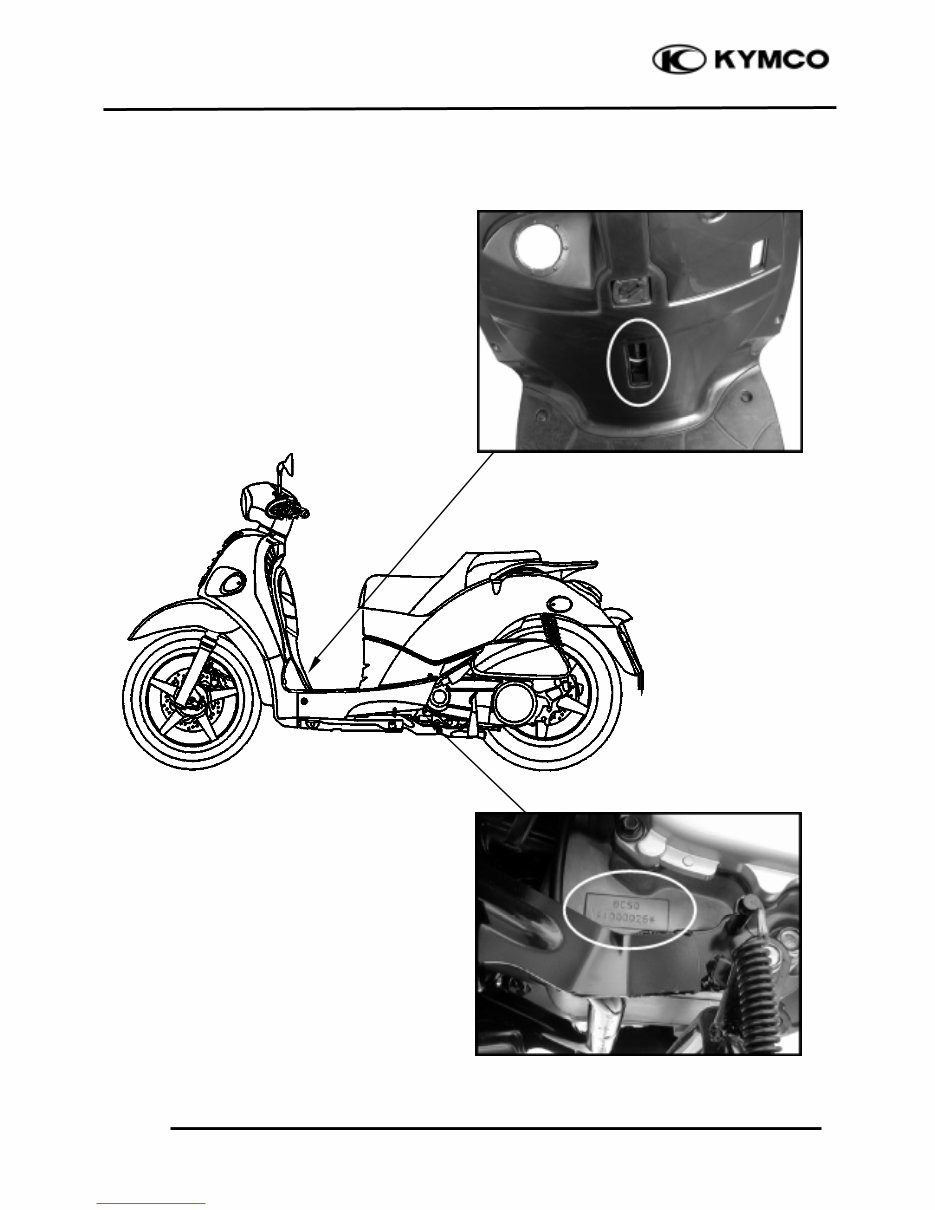
SERIAL NUMBER
Location of Engine Serial Number
Location of Frame Serial Number
Downloaded from www.Manualslib.com manuals search engine
1. GENERAL INFORMATION
1-2
PEOPLE 250
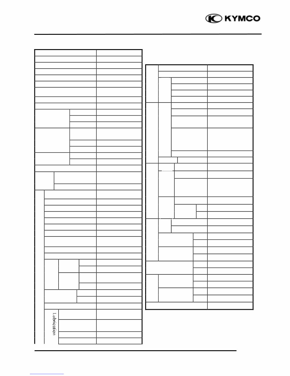
SPECIFICATIONS
Name & Model No. BC50AA
Motorcycle Name & Type PEOPLE 250
Overall length 2219mm
Overall width 742mm
Overall height 1145mm
Wheel base 1515mm
Engine type
Water cooled 4-stroke,
OHC engine
Displacement 249.1cc
Fuel Used 92# nonleaded gasoline
1 person (55kg) Front wheel 86
weight (kg) Rear wheel 127
Total 213
2 person
(110kg)
Front wheel 93
weight(kg) Rear wheel 175
Total 268
Front wheel 110/70-16 52P
Rear wheel 140/70-16 65P
Ground clearance 145mm
Perform
-
Braking distance (m) 4.0m/30km/hr
ance
Min. turning radius 2180mm
Starting system
Starting motor
Type Gasoline, 4-stroke
Cylinder arrangement Single cylinder
Combustion chamber type Semi-sphere
Valve arrangement O.H.C.
Bore x stroke (mm) 72.7 x 60
Compression ratio 10.3:1
Compression pressure
(kg/cm_)
15±2
Max. output (kw/rpm) 13.93/7000
Max. torque (kg.m/rpm) 2.0/5500
BTDC -8°
Port
Intake
ABDC 42°
timin
g
BBDC 33°
Exhaust
ATDC 1°
Valve
Intake 0.1
clearance (cold)
Exhaust 0.1
Idle speed (rpm) 1700±100rpm
Lubrication type
Forced pressure &
Wet sump
Oil pump type Inner/outer rotor
type
Oil filter type Full-flow filtration
Oil capacity 1.1 liters
Air cleaner type & No Paper element, wet
Fuel capacity 8.0 liters
Type CVK
Piston dia. 30
Venturi dia. 30 equivalent
Throttle type Butterfly type
Type CDI
Ignition timing Repeatedly
Contact breaker Non-contact point
type
Spark plug
NGK
DPR7EA-9
Spark plug gap 0.7mm
Battery Capacity 12V10AH
Clutch Type Dry multi-disc clutch
Type Non-stage transmission
Operation
Automatic
centrifugal
Type
Type Two-stage reduction
Reduction 1st 0.83~2.2
ratio
Final 8.72
Front Caster angle 27°
Axle
Connecting rod
Front 1.75
Tire pressure
(kgf/cm_) Rear 2.0
Turning Left 45°
angle
Right 45°
Front Disk brake
Brake system
type Rear Disk brake
Suspension
Front Telescope
type
Rear Double swing
Shock absorber
Front Telescope
type
Rear Double swing
Frame type Under bone
Tires
Engine
System
Fuel System
Carburetor
Electrical
Ignition System
Power Drive System
Transmis-
sion Gear
Reduction
Gear
Moving Device
Damping
Device
Downloaded from www.Manualslib.com manuals search engine
1. GENERAL INFORMATION
1-3
PEOPLE 250
SERVICE PRECAUTIONS
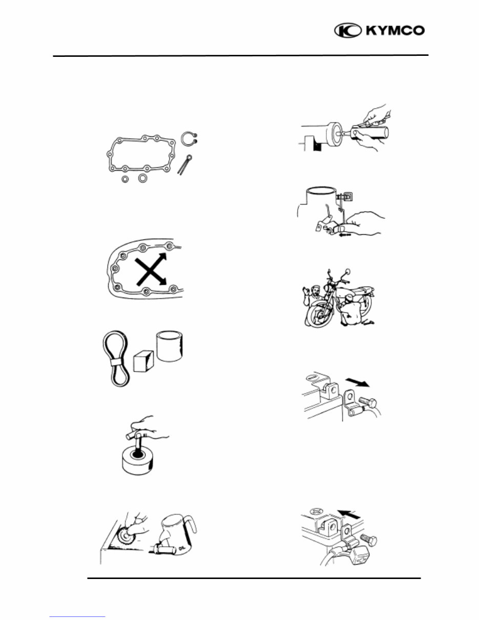
n Make sure to install new gaskets, O-rings,
circlips, cotter pins, etc. when
reassembling.
n When tightening bolts or nuts, begin with
larger-diameter to smaller ones at several
times, and tighten to the specified torque
diagonally.
n Use genuine parts and lubricants.
n When servicing the motorcycle, be sure to
use special tools for removal and
installation.
n After disassembly, clean removed parts.
Lubricate sliding surfaces with engine oil
before reassembly.
n Apply or add designated greases and
lubricants to the specified lubrication
points.
n After reassembly, check all parts for
proper tightening and operation.
n When two persons work together, pay
attention to the mutual working safety.
n Disconnect the battery negative (-) terminal
before operation.
n When using a spanner or other tools, make
sure not to damage the motorcycle surface.
n After operation, check all connecting
points, fasteners, and lines for proper
connection and installation.
n When connecting the battery, the positive
(+) terminal must be connected first.
n After connection, apply grease to the
battery terminals.
n Terminal caps shall be installed securely.
Downloaded from www.Manualslib.com manuals search engine
1. GENERAL INFORMATION
1-4
PEOPLE 250
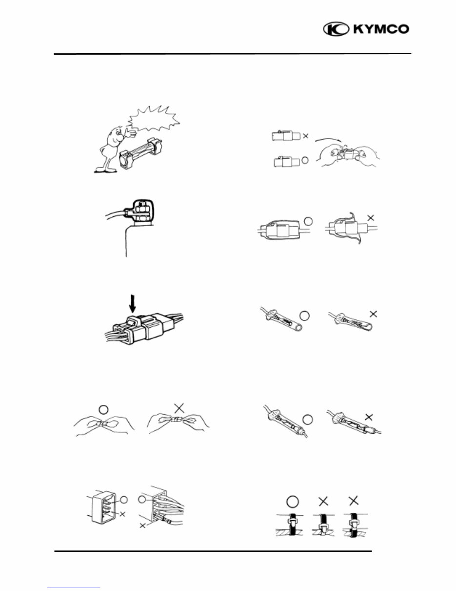
n If the fuse is burned out, find the cause and
repair it. Replace it with a new one
according to the specified capacity.
n After operation, terminal caps shall be
installed securely.
n When taking out the connector, the lock on
the connector shall be released before
operation.
n Hold the connector body when connecting
or disconnecting it.
n Do not pull the connector wire.
n Check if any connector terminal is bending,
protruding or loose.
n The connector shall be inserted
completely.
n If the double connector has a lock, lock
it at the correct position.
n Check if there is any loose wire.
n Before connecting a terminal, check for
damaged terminal cover or loose negative
terminal.
n Check the double connector cover for
proper coverage and installation.
n Insert the terminal completely.
n Check the terminal cover for proper
coverage.
n Do not make the terminal cover opening
face up.
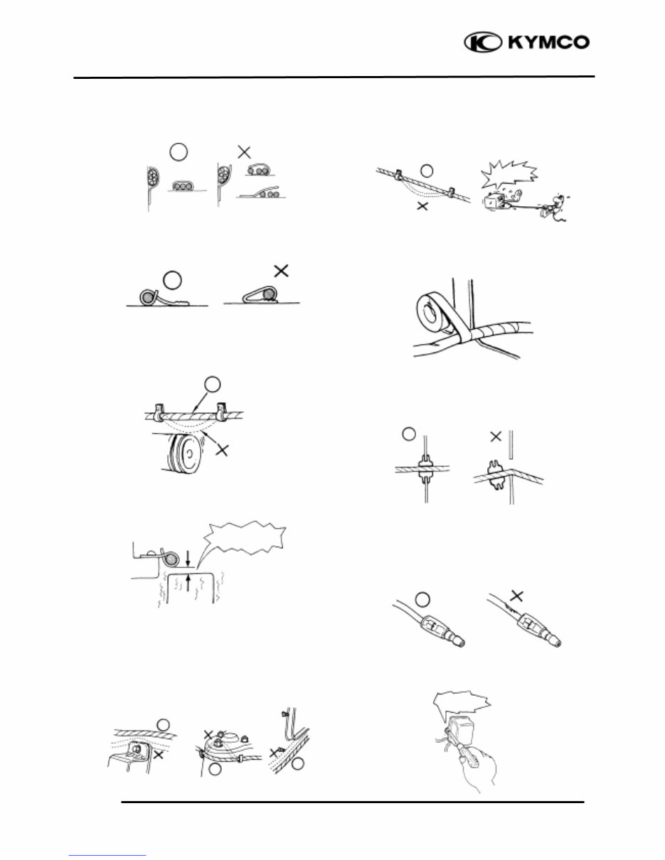
n Secure wire harnesses to the frame with
their respective wire bands at the
designated locations.
Tighten the bands so that only the
insulated surfaces contact the wire
harnesses.
Confirm
Capacity
Downloaded from www.Manualslib.com manuals search engine
1. GENERAL INFORMATION
1-5
PEOPLE 250
n After clamping, check each wire to make
sure it is secure.
n Do not squeeze wires against the weld or
its clamp.
n After clamping, check each harness to make
sure that it is not interfering with any
moving or sliding parts.
n When fixing the wire harnesses, do not
make it contact the parts which will
generate high heat.
n Route wire harnesses to avoid sharp edges
or corners. Avoid the projected ends of
bolts and screws.
n Route wire harnesses passing through the
side of bolts and screws. Avoid the
projected ends of bolts and screws.
n Route harnesses so they are neither
pulled tight nor have excessive slack.
n Protect wires and harnesses with electrical
tape or tube if they contact a sharp edge or
corner.
n When rubber protecting cover is used to
protect the wire harnesses, it shall be
installed securely.
n Do not break the sheath of wire.
n If a wire or harness is with a broken sheath,
repair by wrapping it with protective tape
or replace it.
n When installing other parts, do not press or
squeeze the wires.
Do not pull
too tightð
No Contact
Do not press
or squeeze the
wire
Downloaded from www.Manualslib.com manuals search engine
1. GENERAL INFORMATION
1-6
PEOPLE 250
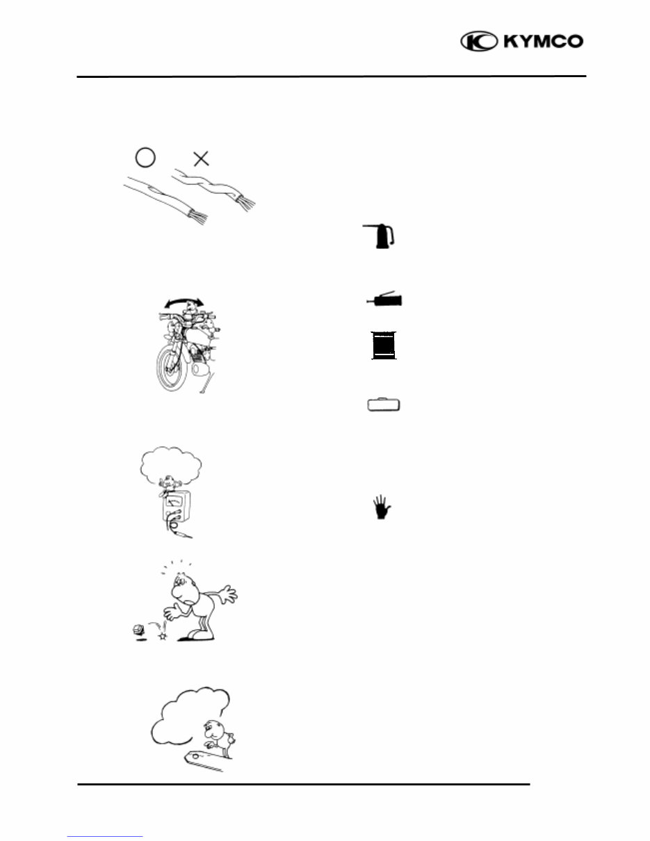
n After routing, check that the wire harnesses
are not twisted or kinked.
n Wire harnesses routed along with handlebar
should not be pulled tight, have excessive
slack or interfere with adjacent or
surrounding parts in all steering positions.
n When a testing device is used, make sure to
understand the operating methods
thoroughly and operate according to the
operating instructions.
n Be careful not to drop any parts.
n When rust is found on a terminal, remove
the rust with sand paper or equivalent
before connecting.
n Symbols:
The following symbols represent the
servicing methods and cautions included in
this service manual.
: Apply engine oil to the
specified points. (Use
designated engine oil for
lubrication.)
: Apply grease for lubrication.
: Transmission Gear Oil (90#)
: Use special tool.
: Caution
: Warning
Special
Engine Oil
Grease
Gear Oil
*
Do you
understand the
instrument?
Remove
Rust∴
Downloaded from www.Manualslib.com manuals search engine

1. GENERAL INFORMATION
1-7
PEOPLE 250
TORQUE VALUES
STANDARD TORQUE VALUES
Item Torque (N-m) Item Torque (N-m)
5mm bolt, nut
6mm bolt, nut
8mm bolt, nut
10mm bolt, nut
12mm bolt, nut
4.5_ 6
8 _ 12
18_ 25
30_ 40
50_ 60
5mm screw
6mm screw, SH bolt
6mm flange bolt, nut
8mm flange bolt, nut
10mm flange bolt, nut
3.5_ 5
7 _ 11
10_ 14
24_ 30
35_ 45
Torque specifications listed below are for important fasteners.
ENGINE
Item Q‘ty Thread dia.(mm) Torque (N-m) Remarks
Cylinder head bolt A
Cylinder head bolt B
Oil filter screen cap
Cylinder head cap nut
Valve adjusting lock nut
Cam chain tensioner slipper bolt
Oil bolt
Clutch outer nut
Clutch drive plate nut
Flywheel nut
Oil pump bolt
Cylinder head cover bolt
Spark plug
Cam chain tensioner bolt
Water pump impeller
Drive face nut
Transmission case cover bolt
Gear oil check bolt
2
2
1
4
2
1
1
1
1
1
2
4
1
1
1
1
9
1
8
8
30
8
5
6
12
12
12
14
5
6
10
6
8
12
8
8
8.9
8.9
12.7
24.5
8.8
8.8
14.7
53.9
53.9
58.8
3.9
11.8
17.2
11.8
11.8
93
20
10
Double end bolt
Double end bolt
Apply oil to
threads
Downloaded from www.Manualslib.com manuals search engine
You're Reading a Preview
What's Included?
Fast Download Speeds
Online & Offline Access
Access PDF Contents & Bookmarks
Full Search Facility
Print one or all pages of your manual
$33.99
Viewed 87 Times Today


Secure transaction
What's Included?
Fast Download Speeds
Online & Offline Access
Access PDF Contents & Bookmarks
Full Search Facility
Print one or all pages of your manual
$33.99
This manual is a comprehensive guide used by professional technicians and DIY enthusiasts for maintaining, servicing, diagnosing, and repairing vehicles. It includes step-by-step instructions, diagrams, illustrations, wiring schematics, and specifications for easy vehicle repair. All pages are printable, allowing for convenient access to the necessary information at the vehicle or workshop.
- General Information
- Exhaust Muffler/Frame Covers
- Inspection/Adjustment
- Lubrication System
- Engine Removal/Installation
- Cylinder Head/Cylinder/Piston
- Kick Starter/Drive
- Pulley/Clutch/Driven Pulley
- Final Reduction
- A.C. Generator
- Crankcase/Crankshaft
- Cooling System
- Carburetor/Fuel Pump
- Steering Handlebar/Front Wheel/Front Brake/Front Shock Absorber/Front Fork
- Rear Brake/Rear Fork/Rear Wheel/Rear Shock Absorber
- Fuel Tank
- Battery/Charging System
- Ignition System
- Starting System
- Switches/Horn/Fuel Unit
- Thermo-Static Switch/Temperature Gauge/Instruments/Lights
- High-Speed Tire (Tubeless Tire)
- And more...
Format: PDF
Language: English
Compatible: Win/Mac


