

KYMCO AGILITY CITY 125 Full Service & Repair Manual
What's Included?
Fast Download Speeds
Online & Offline Access
Access PDF Contents & Bookmarks
Full Search Facility
Print one or all pages of your manual

AGILITY 125
PREFACE
This Service Manual describes the
technical features and servicing
procedures for the KYMCO AGILITY 125
Section 1 contains the precautions for all
operations stated in this manual. Read
them carefully before starting any
operation.
Section 2 is the removal/installation
procedures for the frame covers which
are subject to higher removal/installation
frequency during maintenance and
servicing operations.
Section 3 describes the inspection/
adjustment procedures, safety rules and
service information for each part, starting
from periodic maintenance.
Sections 6 through 17 give instructions
for disassembly, assembly and inspection
of engine, chassis frame and electrical
equipment.
Most sections start with an assembly or
system illustration and troubleshooting
for the section. The subsequent pages
give detailed procedures for the section.
KWANG YANG MOTOR CO., LTD.
OVERSEAS SALES DEPARTMENT
OVERSEAS SERVICE SECTION
TABLE OF CONTENTS
GENERAL INFORMATION 1
FRAME COVERS/EXHAUST MUFFLER 2
INSPECTION/ADJUSTMENT 3
LUBRICATION SYSTEM 4
FUEL SYSTEM 5
ENGINE REMOVAL/INSTALLATION 6
CYLINDER HEAD/VALVES 7
CYLINDER/PISTON 8
ENGINE
DRIVE AND DRIVEN PULLEYS/KICK
STARTER
9
FINAL REDUCTION 10
CRANKCASE/CRANKSHAFT 11
FRONT WHEEL/FRONT BRAKE/
FRONT SUSPENSION
12
CHASSIS
REAR WHEEL /REAR BRAKE /REAR
SUSPENSION
13
BATTERY/CHARGING SYSTEM/A.C.
GENERATOR
14
IGNITION SYSTEM 15
STARTING SYSTEM 16
ELECTRICAL
EQUIPMENT
LIGHTS/INSTRUMENTS/SWITCHES 17
Our company reserves the right to make
any alteration in the design.
The information and contents included
in this manual may be different from
the motorcycle in case specifications
are changed.
1. GENERAL INFORMATION
1-1
AGILITY 125
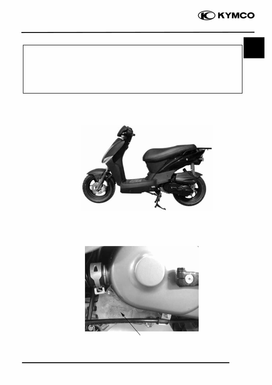
Location of Engine Serial Number
ENGINE SERIAL NUMBER
1 ENGINE SERIAL NUMBER ................... 1- 1 LUBRICATION POINTS ....................... 1-13
SPECIFICATIONS ................................... 1- 2 CABLE & HARNESS ROUTING ............ 1-15
SERVICE PRECAUTIONS ...................... 1- 3 WIRING DIAGRAM................................ 1-20
TORQUE VALUES .................................. 1-11 TROUBLESHOOTUNG .......................... 1-21
SPECIAL TOOLS ..................................... 1-12
AGILITY 125
1. GENERAL INFORMATION
1-2
AGILITY 125
SPECIFICATIONS
Motorcycle Name & Type AGILITY 125
Name & Model No. LDF7
Overall length (mm) 1830
Overall width (mm) 690
Overall height (mm) 1130
Wheel base (mm) 1300
Engine type O.H.C.
Displacement 124.6cc
Fuel Used 92# nonleaded gasoline
Front wheel 40
Net weight (kg) Rear wheel 65.5
Total 105.5
Front wheel 40
Gross weight(kg) Rear wheel 69.5
Total 109.5
Front wheel 120/70 -12 56J
Tires
Rear wheel 130/70 -12 56J
Ground clearance (mm) 127
Perform-
Braking distance (m)
7 (Initial speed
30km/h)
ance
Min. turning radius (m) 1.99
Starting system
Starting motor &
kick starter
Type Gasoline, 4-stroke
Cylinder arrangement Single cylinder
Combustion chamber type Semi-sphere
Valve arrangement O.H.C.
Bore x stroke (mm) φ52.4 x 57.8
Compression ratio 9.6±0.2
Compression pressure
(kg/cm²-rpm)
13±2
Max. output 6.9/7500kw/(r/min)
Max. torque 9.1/6500N.m/rpm
Open -2.5°
Port
Intake
Close 32°
Engine
timing
Open -3°
Exhaust
Close 3°
Valve clearance
Intake 0.12
(cold) (mm) Exhaust 0.12
Idle speed (rpm) 1700±100rpm
Lubrication type
Forced pressure &
wet sump
Oil pump type Inner/outer rotor type
Oil filter type Full-flow filtration
Lubrication
System
Oil capacity 0.8 liter
Cooling Type Forced air cooling
Air cleaner type & No Paper element, wet
Fuel capacity 5 liter
Type CVK
Piston dia. (mm) φ22
Venturi dia.(mm) φ37equivalent
Carburetor
Throttle type Butterfly type
Type CDI
Ignition timing BTDC27°±2°/4000rpm
Contact breaker Non-contact point type
Spark plug
CHAMPION P-
RZ9 HC
Spark plug gap 0.6~0.7mm
Battery Capacity 12V7AH
Clutch Type Dry multi-disc clutch
Type Non-stage transmission
Operation
Automatic centrifugal
type
Type Two-stage reduction
Reduction 1st 0.95-2.8
ratio
2nd 2.94
Front Caster angle 27°
Axle
Trail length ⎯
Tire pressure
Front 1.75
(kg/cm²)
Rear 2.25
Turning Left 45°
angle
Right 45°
Front DISK (160mm) brake
Brake system
type
Rear Drum (140mm) brake
Front TELESCOPE
Suspension type
Rear Unit Swing
Front 410.1±2.5mm Shock absorber
distance
Rear 351.6±2mm
Frame type Steel Pipel
Fuel System
Electrical Equipment
Ignition System
Power Drive System
Transmis-
sion Gear
Reduction
Gear
Moving Device
Damping
Device
1. GENERAL INFORMATION
1-3
AGILITY 125
SERVICE PRECAUTIONS
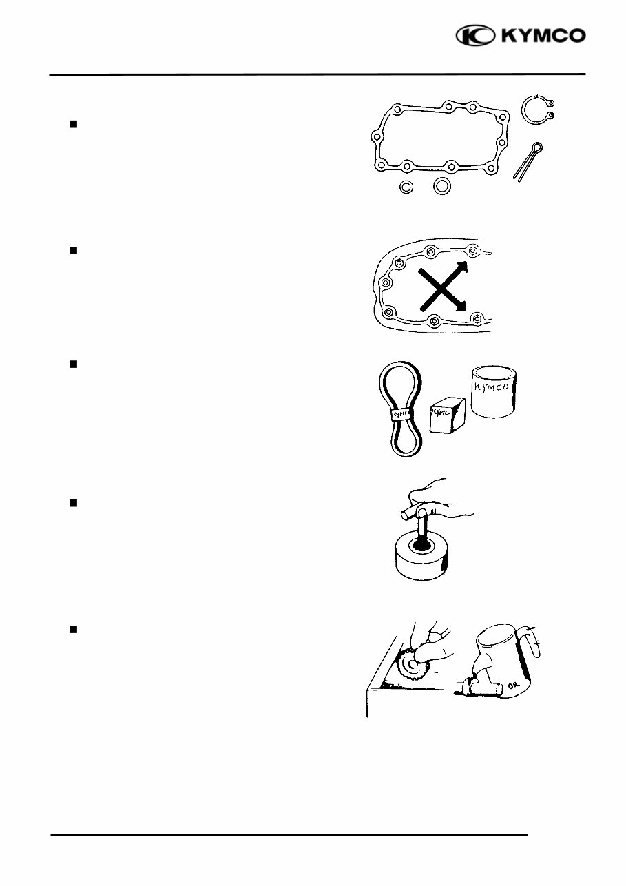
Make sure to install new gaskets, O-rings,
circlips, cotter pins, etc. when
reassembling.
When tightening bolts or nuts, begin with
larger-diameter to smaller ones at several
times, and tighten to the specified torque
diagonally.
Use genuine parts and lubricants
.
When servicing the motorcycle, be sure to
use special tools for removal and
installation.
After disassembly, clean removed parts.
Lubricate sliding surfaces with engine oil
before reassembly.
1. GENERAL INFORMATION
1-4
AGILITY 125
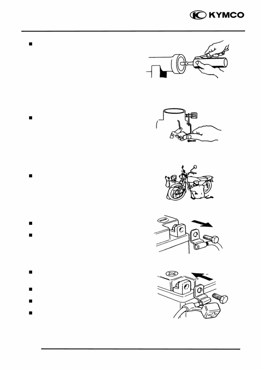
Apply or add designated greases and
lubricants to the specified lubrication
points.
After reassembly, check all parts for proper
tightening and operation.
When two persons work together, pay
attention to the mutual working safety.
Disconnect the battery negative (-) terminal
before operation.
When using a spanner or other tools, make
sure not to damage the motorcycle surface.
After operation, check all connecting
points, fasteners, and lines for proper
connection and installation.
When connecting the battery, the positive
(+) terminal must be connected first.
After connection, apply grease to the
battery terminals.
Terminal caps shall be installed securely.
1. GENERAL INFORMATION
1-5
AGILITY 125
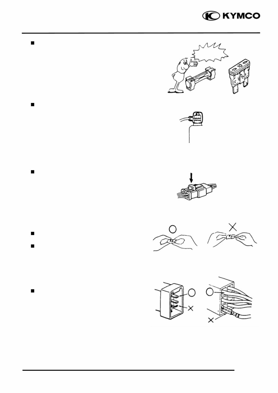
If the fuse is burned out, find the cause and
repair it. Replace it with a new one
according to the specified capacity.
After operation, terminal caps shall be
installed securely.
When taking out the connector, the lock on
the connector shall be released before
operation.
Hold the connector body when connecting
or disconnecting it.
Do not pull the connector wire.
Check if any connector terminal is bending,
protruding or loose.
Confirm
Capacity
1. GENERAL INFORMATION
1-6
AGILITY 125
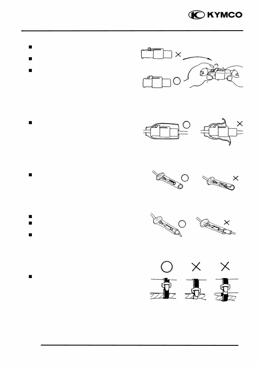
The connector shall be inserted
completely.
If the double connector has a lock, lock
it at the correct position.
Check if there is any loose wire.
Before connecting a terminal, check for
damaged terminal cover or loose
negative terminal.
Check the double connector cover for
proper coverage and installation.
Insert the terminal completely.
Check the terminal cover for proper
coverage.
Do not make the terminal cover opening
face up.
Secure wire harnesses to the frame with
their respective wire bands at the
designated locations.
Tighten the bands so that only the insulated
surfaces contact the wire harnesses.
Snapping!
1. GENERAL INFORMATION
1-7
AGILITY 125
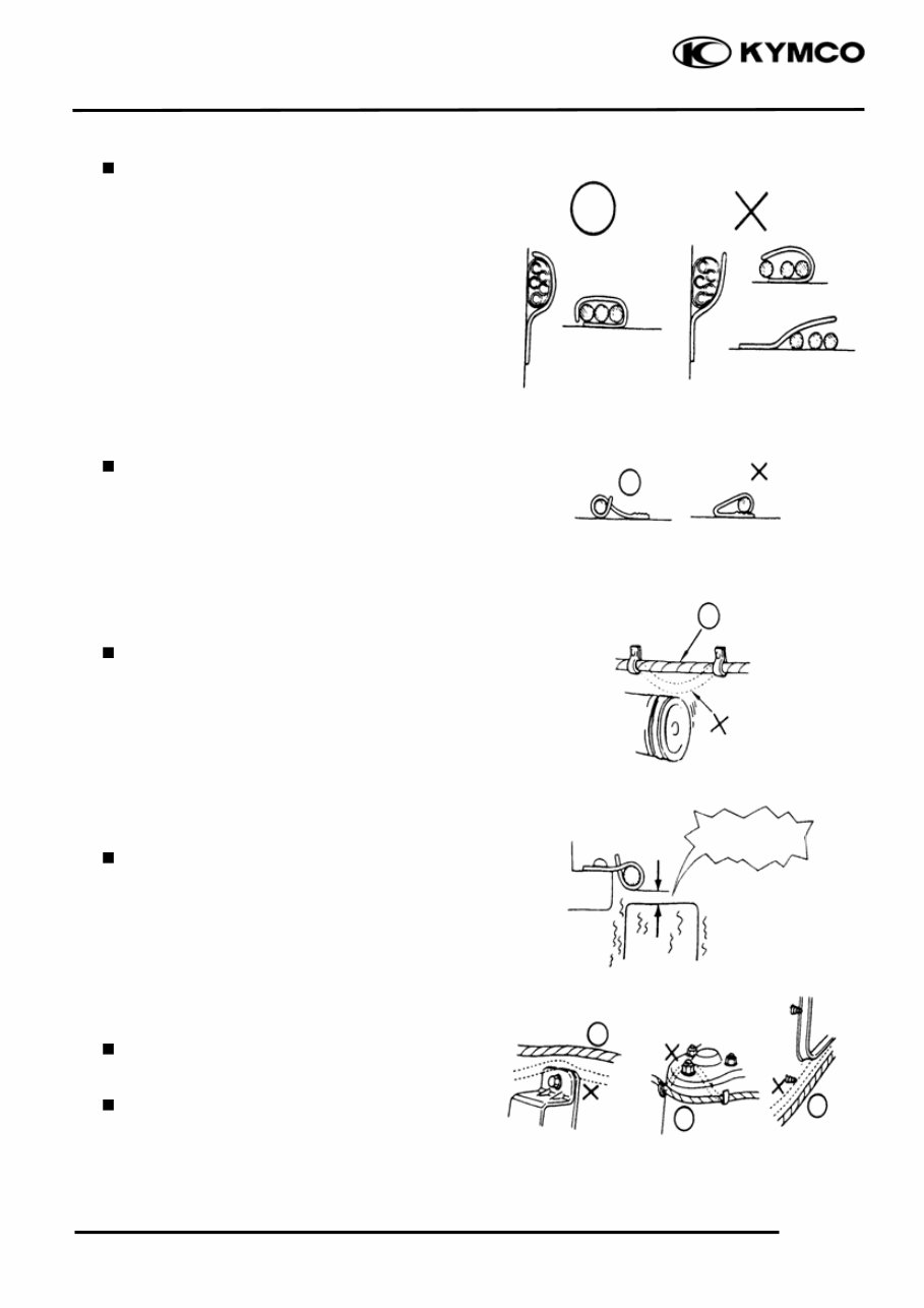
After clamping, check each wire to make
sure it is secure.
.
Do not squeeze wires against the weld or
its clamp
After clamping, check each harness to
make sure that it is not interfering with any
moving or sliding parts.
When fixing the wire harnesses, do not
make it contact the parts which will
generate high heat.
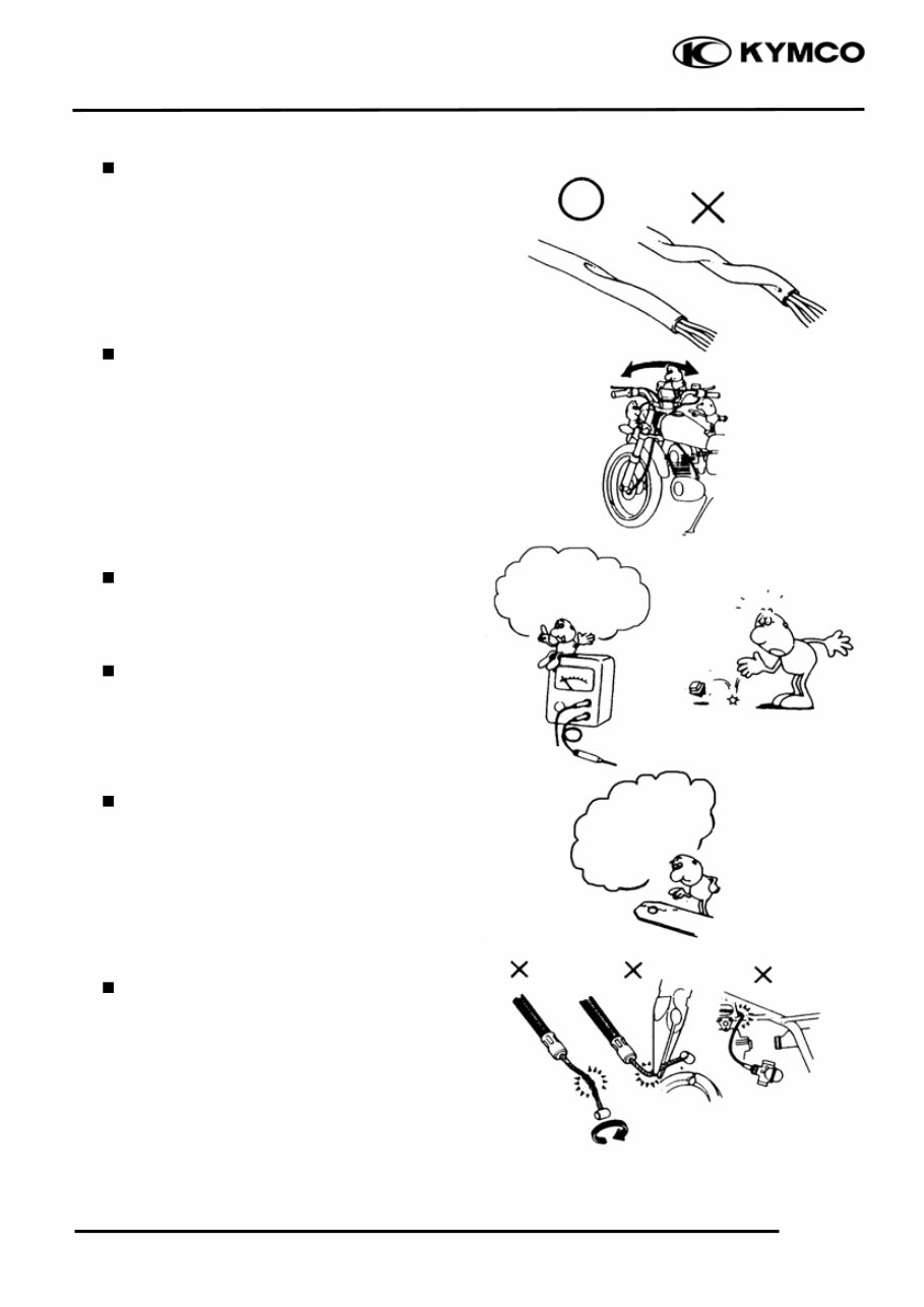
Route wire harnesses to avoid sharp edges
or corners. Avoid the projected ends of
bolts and screws.
Route wire harnesses passing through the
side of bolts and screws. Avoid the
projected ends of bolts and screws.
No Contact !
1. GENERAL INFORMATION
1-8
AGILITY 125
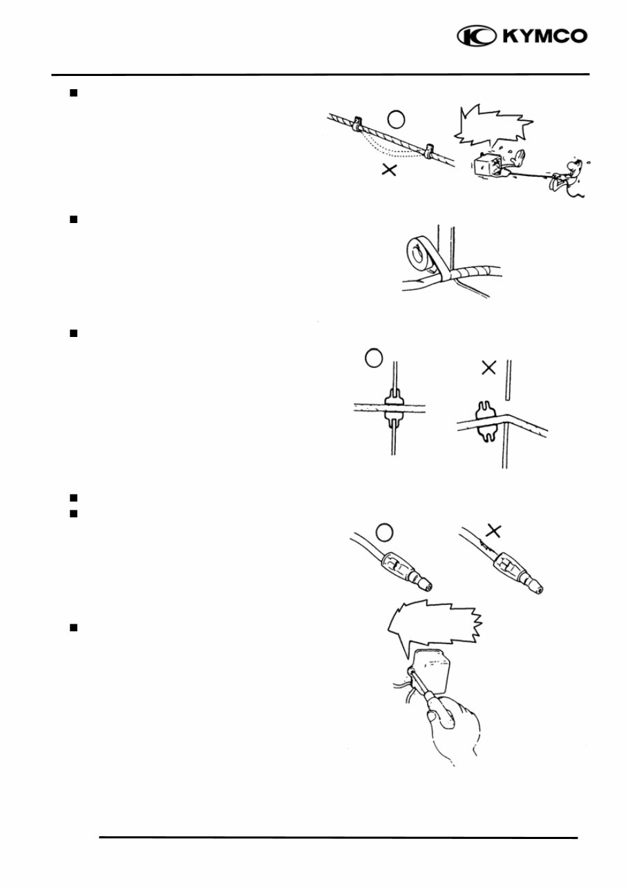
Route harnesses so they are neither
pulled tight nor have excessive slack.
.
Protect wires and harnesses with electrical
tape or tube if they contact a sharp edge or
corner
When rubber protecting cover is used to
protect the wire harnesses, it shall be
installed securely.
Do not break the sheath of wire.
If a wire or harness is with a broken sheath,
repair by wrapping it with protective tape
or replace it.
When installing other parts, do not press or
squeeze the wires.
Do not pull
too tight!
Do not press or
squeeze the wire.
1. GENERAL INFORMATION
1-9
AGILITY 125
After routing, check that the wire harnesses
are not twisted or kinked.
Wire harnesses routed along with
handlebar should not be pulled tight, have
excessive slack or interfere with adjacent
or surrounding parts in all steering
positions.
When a testing device is used, make sure to
understand the operating methods
thoroughly and operate according to the
operating instructions.
Be careful not to drop any parts.
When rust is found on a terminal, remove
the rust with sand paper or equivalent
before connecting.
Do not bend or twist control cables.
Damaged control cables will not operate
smoothly and may stick or bind.
Do you understand
the instrument? Is
the instrument set
correctly?
Remove Rust !
You're Reading a Preview
What's Included?
Fast Download Speeds
Online & Offline Access
Access PDF Contents & Bookmarks
Full Search Facility
Print one or all pages of your manual
$31.99
Viewed 69 Times Today


Secure transaction
What's Included?
Fast Download Speeds
Online & Offline Access
Access PDF Contents & Bookmarks
Full Search Facility
Print one or all pages of your manual
$31.99
Get instant access to the Complete Factory Service Repair Workshop Manual without any extra fees or expiry dates. This Professional Manual is suitable for both professional Mechanics and Technicians, as well as DIY enthusiasts. It covers all repairs, servicing, and troubleshooting procedures with detailed photos, diagrams, step-by-step instructions, and highly detailed exploded diagrams & pictures to ensure every job is completed correctly.
Print out a single page or the entire manual as per your choice. This Manual can be used on multiple computers without any limitations or trial periods, and it does not expire or require any renewal fees. It is fully compatible with all Windows & MAC Computers.


