

REPAIR MANUAL 2005
BEDIENUNGSANLEITUNGEN
OWNER’S MANUAL
MANUALE O’USO
MANUEL D’UTILISATION
MANUAL DE INSTRUCCIONES
REPARATURANLEITUNG
REPAIR MANUAL
MANUALE DI REPARAZIONE
MANUEL DE REPARATION
MANUAL DE REPARACION
FEDERBEIN
SHOCK ABSORBER
AMMORTIZZATORE
AMMORTISSEUR
AMORTIGUADOR
GABEL
FORK
FORCELLA
FOURCHE
HORQUILLA
OWNER`S MANUAL
MANUALE D`USO
MANUEL D`UTILISATION
MANUAL DE INSTRUCCIONES
ART. NR. 3.211.39
250 EXC RACING
400 EXC RACING
450 SX, MXC, EXC RACING
525 SX, MXC, EXC RACING
OWNER'S MANUAL 2005

ENGLISH
2
INTRODUCTION »
We would like to congratulate you on your purchase of a KTM motorcycle.
You are now the owner of a state-of-the-art sport motorcycle that guarantees to bring you lots of fun and
enjoyment, provided that you clean and maintain it appropriately. Before you go for your first ride, be sure
to read this manual carefully and thoroughly in order to familiarize yourself with how to operate your new
motorcycle and with its characteristics, even if this means that you will have to dedicate some of your
valuable time to this task. Only by doing so will you learn how to tune your motorcycle to your specific
needs and how to protect yourself against injury. Besides, this manual contains important information on
motorcycle maintenance. At the time this manual was typeset, it was up-to-date with the latest state of
this production series. It cannot be completely ruled out, however, that minor discrepancies may exist
resulting from further design upgrades of these motorcycles.This manual is an important part of your motor-
cycle and should be passed on to any subsequent owner in case you decide to sell it.
We expressly point out that work marked with an asterisk in the chapter "Maintenance work on the chas-
sis and engine" must be performed. If maintenance work should become necessary during a competition
it should be performed by a trained mechanic. KTM strongly recommends that all service work to your
KTM should be performed by a qualified KTM dealer.
For your own safety, use KTM-approved parts and accessories only. KTM is not liable for damage that
arises in connection with the use of other products.
Take special care to follow the recommended run in, inspection, and maintenance intervals. Heeding
these guidelines will significantly increase the life of your motorcycle. To ensure that all work to your KTM
is performed properly and to avoid warranty conflicts, KTM recommends that you always have your KTM
serviced by a recognized and qualified KTM dealer.
Off-road motorcycle driving is a wonderful sport and we hope that you will be able to enjoy it to the full.
It may, however, involve potential problems for the environment or lead to conflicts with others. These
problems or conflicts can be avoided if the motorcycle is used responsibly. To safeguard the future of
motorcycle sports, make sure that you use the motorcycle in accordance with the law, show that you are
environmentally conscious and respect the rights of others.
We wish you a lot of fun when driving !
KTM-SPORTMOTORCYCLE AG
5230 MATTIGHOFEN, AUSTRIA
Attachments: 1 spare parts manual chassis & engine

ENGLISH
3
IMPORTANT LIMITED WARRANTY AND LIMITED GUARANTEE INFORMATION »
KTM sports motorcycles are designed and constructed to resist the usual wear and tear of normal use in
competitions.
The motorcycles comply with the regulations and categories currently in effect with the leading interna-
tional motorcycle associations.
Observance of the service, maintenance and tuning instructions for the engine and chassis specified in
the Owner's Manual is a prerequisite for faultless operation and the avoidance of premature wear. An
improperly tuned chassis can lead to damage and breakage of the chassis components (see chapter on
checking the basic chassis setting).
The service work specified in the "Lubrication and Maintenance Schedule" must be performed and serv-
ice records must be kept for warranty documentation. Lack of proper service and maintenance records or
documentation could void warranty.
The fuels and lubricants specified in the Owner's Manual or fluids with equivalent specifications must
be used in accordance with the maintenance schedule.
No claims can be filed under the warranty for damage or consequential damage caused by manipulations
or conversions to the motorcycle.
The use of the motorcycle under extreme conditions, e.g. on extremely muddy and wet terrain, can lead
to higher than average wear on components such as the drive train or the brakes. In this case it may
become necessary to service or replace wear parts before the service limit specified in the maintenance
schedule has been reached.
The SX/SXS, MXC and other “competition only“ labeled models are prohibited on public roads.
“On the road“ approved models are only allowed on public roads in the original homologated (throttled)
version. Without this performance restriction (i.e. de-throttled), these models are only allowed to be driven
off-road and not on public roads.
The EXC models are designed for off-road sports endurance competitions(enduro) and not suitable for
predominant motocross use.
Note: The above is a general statement. Specific limited warranty and limited guarantee information may
vary depending upon distribution. Please check with your local KTM dealer for limited warranty and lim-
ited guarantee information specific to your KTM model and region.
In accordance with the international quality management ISO 9001 standard, KTM uses
quality assurance processes that lead to the highest possible product quality.

ENGLISH
4
TABLE OF CONTENTS »
Page
IMPORTANT LIMITED WARRANTY AND LIMITED GUARAN-
TEE INFORMATION . . . . . . . . . . . . . . . . . . . . . . . . . . . .3
SERIAL NUMBER LOCATIONS . . . . . . . . . . . . . . . . . . . .5
Chassis number . . . . . . . . . . . . . . . . . . . . . . . . . . . .5
Engine number, engine type . . . . . . . . . . . . . . . . . . . .5
OPERATION INSTRUMENTS . . . . . . . . . . . . . . . . . . . . .6
Clutch lever . . . . . . . . . . . . . . . . . . . . . . . . . . . . . . .6
Hand decompression lever . . . . . . . . . . . . . . . . . . . . .6
Hand brake lever . . . . . . . . . . . . . . . . . . . . . . . . . . . .6
Short circuit button (SX/MXC) . . . . . . . . . . . . . . . . . . .6
Combination switch (EXC) . . . . . . . . . . . . . . . . . . . . .6
Flasher switch . . . . . . . . . . . . . . . . . . . . . . . . . . . . . .7
Starter button (EXC) . . . . . . . . . . . . . . . . . . . . . . . . .7
Emergency OFF switch (EXC Australia) . . . . . . . . . . . .7
Digital speedometer, indicator lamps . . . . . . . . . . . . . .7
Electronic speedometer . . . . . . . . . . . . . . . . . . . . . . .8
Setting the clock . . . . . . . . . . . . . . . . . . . . . . . . . .12
Filler cap . . . . . . . . . . . . . . . . . . . . . . . . . . . . . . . .13
Fuel tap . . . . . . . . . . . . . . . . . . . . . . . . . . . . . . . . .13
Choke . . . . . . . . . . . . . . . . . . . . . . . . . . . . . . . . . .13
Hot start device (450/525 SX) . . . . . . . . . . . . . . . . .13
Shift lever . . . . . . . . . . . . . . . . . . . . . . . . . . . . . . .14
Kickstarter . . . . . . . . . . . . . . . . . . . . . . . . . . . . . . .14
Foot brake pedal . . . . . . . . . . . . . . . . . . . . . . . . . . .14
Side stand . . . . . . . . . . . . . . . . . . . . . . . . . . . . . . .14
Steering lock . . . . . . . . . . . . . . . . . . . . . . . . . . . . .14
Compression damping of fork . . . . . . . . . . . . . . . . . .15
Rebound damping of fork . . . . . . . . . . . . . . . . . . . . .15
Damping action during compression of shock absorber (SX) .15
Compression damping of shock absorber (MXC, EXC) .16
Rebound damping of shock absorber (SX, MXC, EXC) .16
GENERAL TIPS AND WARNINGS FOR STARTING THE
MOTORCYCLE . . . . . . . . . . . . . . . . . . . . . . . . . . . . . .17
Instructions for initial operation . . . . . . . . . . . . . . . .17
Running in the Racing models . . . . . . . . . . . . . . . . .17
DRIVING INSTRUCTIONS . . . . . . . . . . . . . . . . . . . . . .18
Check the following before each start . . . . . . . . . . . .18
Starting when the engine is cold . . . . . . . . . . . . . . . .19
Starting when the engine is warm . . . . . . . . . . . . . . .19
What to do when the engine is “flooded” . . . . . . . . . .19
Starting off . . . . . . . . . . . . . . . . . . . . . . . . . . . . . . .19
Shifting/Riding . . . . . . . . . . . . . . . . . . . . . . . . . . . .19
Braking . . . . . . . . . . . . . . . . . . . . . . . . . . . . . . . . .20
Stopping and parking . . . . . . . . . . . . . . . . . . . . . . . .20
Fuel . . . . . . . . . . . . . . . . . . . . . . . . . . . . . . . . . . . .20
PERIODIC MAINTENANCE . . . . . . . . . . . . . . . . . . . . . .21
MAINTENANCE WORK ON CHASSIS AND ENGINE . . . .24
Changing the spring preloading of the shock absorber .25
Pivot bearing . . . . . . . . . . . . . . . . . . . . . . . . . . . . .25
Basic suspension setup for the weight of the driver . . .26
Checking the shock absorber and spring . . . . . . . . . .26
Determining the static sag of the shock absorber . . . .26
Determining the riding sag of the shock absorber . . . .26
Checking the basic setup of the telescopic fork . . . . .27
Changing the spring preload on the telescopic fork
(SX models) . . . . . . . . . . . . . . . . . . . . . . . . . . . . . .27
Changing the spring preload on the telescopic fork
(MXC/EXC models) . . . . . . . . . . . . . . . . . . . . . . . . .27
Replacing fork springs . . . . . . . . . . . . . . . . . . . . . . .27
Page
Breather plug front fork . . . . . . . . . . . . . . . . . . . . . .28
Cleaning the dust sleeves of the telescopic fork . . . . .28
Checking and adjusting the steering head bearing . . .28
Changing the fork offset (caster) (SX) . . . . . . . . . . . .29
Checking and adjusting the steering head bearing . . .30
Check chain tension . . . . . . . . . . . . . . . . . . . . . . . .31
Correct chain tension . . . . . . . . . . . . . . . . . . . . . . . .31
Chain maintenance . . . . . . . . . . . . . . . . . . . . . . . . .32
Chain wear . . . . . . . . . . . . . . . . . . . . . . . . . . . . . . .32
General information about KTM disc brakes . . . . . . . .33
Adjusting the free travel at the hand brake lever . . . . .34
Checking the brake fluid level - front brake . . . . . . . .34
Refilling the front brake fluid reservoir . . . . . . . . . . .34
Checking the front brake pads . . . . . . . . . . . . . . . . .34
Replacing the front brake pads . . . . . . . . . . . . . . . . .35
Changing the basic position of the foot brake pedal . .35
Checking the rear brake fluid level . . . . . . . . . . . . . .35
Refilling the rear brake fluid reservoir . . . . . . . . . . . .35
Checking the rear brake pads . . . . . . . . . . . . . . . . . .36
Replacing the rear brake pads . . . . . . . . . . . . . . . . .36
Dismounting and mounting the front wheel . . . . . . . .36
Dismounting and mounting the rear wheel . . . . . . . . .37
Checking spoke tension . . . . . . . . . . . . . . . . . . . . . .37
Tires, air pressure . . . . . . . . . . . . . . . . . . . . . . . . . .38
Check/set distance of the magnetic sensor . . . . . . . . .38
Replacing the battery of the digital speedometer . . . .38
Battery (MXC/EXC) . . . . . . . . . . . . . . . . . . . . . . . . .39
Charging the battery . . . . . . . . . . . . . . . . . . . . . . . .39
Fuse (MXC/EXC) . . . . . . . . . . . . . . . . . . . . . . . . . . .40
Replacing headlight lamp/parking light lamp . . . . . . .40
Cooling system . . . . . . . . . . . . . . . . . . . . . . . . . . . .41
Checking the coolant level . . . . . . . . . . . . . . . . . . . .41
Bleeding the cooling system . . . . . . . . . . . . . . . . . . .41
Replacing the glassfiber yarn packing of the silencer .42
Cleaning the spark arrester (MXC/EXC USA) . . . . . . . .42
Cleaning the air filter . . . . . . . . . . . . . . . . . . . . . . . .43
Checking the adjustment of the hand decompression
release cable . . . . . . . . . . . . . . . . . . . . . . . . . . . . .43
Adjusting the throttle cables . . . . . . . . . . . . . . . . . . .43
Changing the original position of the clutch lever . . . .44
Checking the oil level of the hydraulic clutch . . . . . .44
Bleeding of the hydraulic clutch . . . . . . . . . . . . . . . .44
CARBURETOR – Adjust idling (Keihin-FCRMX 37/39/41) .45
Adjusting the mixture control screw . . . . . . . . . . . . .45
Checking the float level (float height) . . . . . . . . . . . .45
Draining the float chamber of the carburetor . . . . . . .46
Oil circuit . . . . . . . . . . . . . . . . . . . . . . . . . . . . . . . .46
Checking the engine oil level . . . . . . . . . . . . . . . . . .46
Engine oil . . . . . . . . . . . . . . . . . . . . . . . . . . . . . . . .47
Changing the engine oil . . . . . . . . . . . . . . . . . . . . . .47
TROUBLESHOOTING . . . . . . . . . . . . . . . . . . . . . . . . .49
STORAGE . . . . . . . . . . . . . . . . . . . . . . . . . . . . . . . . . .51
CONSERVATION FOR WINTER OPERATION . . . . . . . . . .51
USE AFTER A PERIOD OF STORAGE . . . . . . . . . . . .51
CLEANING . . . . . . . . . . . . . . . . . . . . . . . . . . . . . . . . .51
TECHNICAL DATA - ENGINE . . . . . . . . . . . . . . . . . . . .52
TECHNICAL DATA - CHASSIS . . . . . . . . . . . . . . . . . . . .55
WIRING DIAGRAM . . . . . . . . . . . . . . . . . . . . . . .appendix
ENGLISH
5
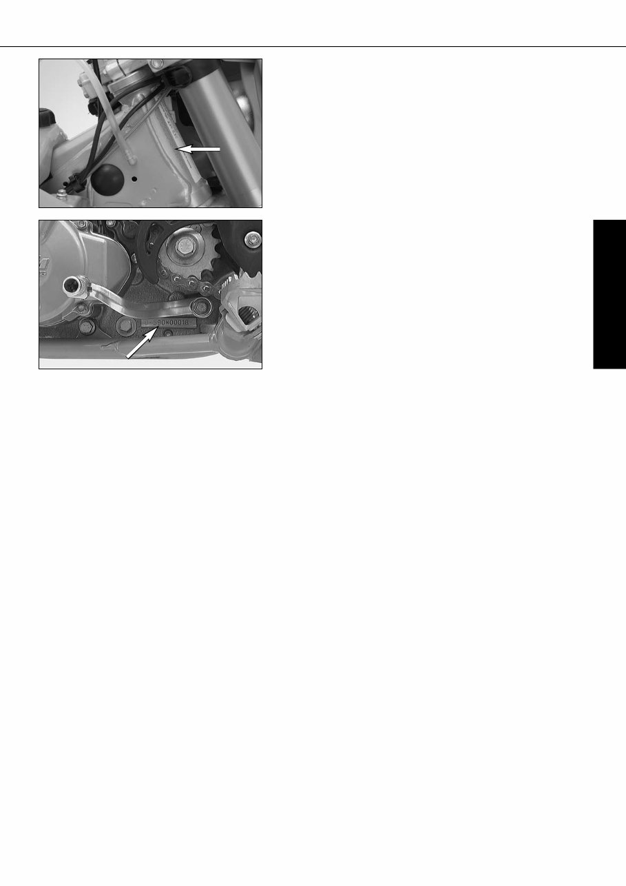
SERIAL NUMBER LOCATIONS »
Chassis number
The chassis number is stamped on the right side of the steering head tube.
Enter this number in the field on page no 1.
Engine number, engine type
The engine number and the engine type are stamped into the left side of the
engine below the engine sprocket. Enter this number on page 1.
ENGLISH
6
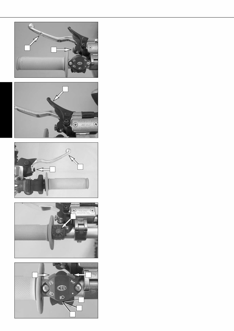
OPERATION INSTRUMENTS »
Clutch lever
The clutch lever [1] is located on the left side of the handlebar. The adjust-
ing screw [A] is used to change the original position of the clutch lever (see
maintenance work on chassis and engine).
The clutch is hydraulically actuated and adjusts itself automatically.
Hand decompression lever
The hand decompression lever [2] is needed only if the carburetor overflows
after a fall. To "pump the engine free", pull the hand decompression lever
during the starting procedure.
The outer end of the lever must provide for a backlash of approx. 10mm (0.4
in) at all times. Only thereafter may it cause valve motion (to be
recognized by the stronger resistance which the hand decompression lever
encounters).
Hand brake lever
The hand brake lever [3] is mounted on the handlebars on the right and
actuates the front wheel brake. The adjusting screw [B] can be used to change
the basic position of the hand brake lever (see "Maintenance").
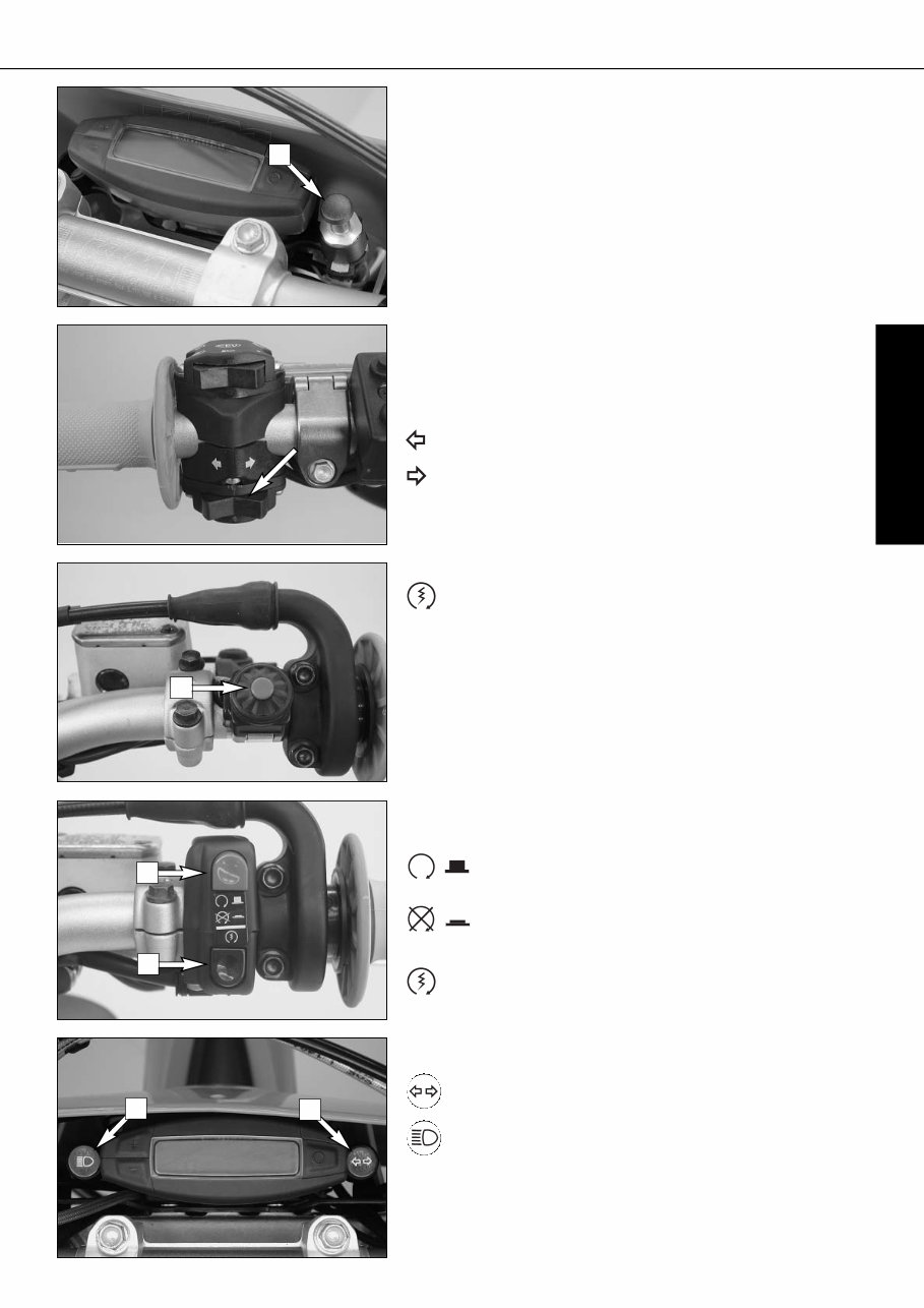
Short circuit button (SX/MXC)
The short circuit button [4] turns off the engine. When pressing this button,
the ignition circuit is short-circuited.
Combination switch (EXC)
The light switch has 2, respectively 3 switch positions.
[A] = Light off (this function is not available in all models)
[B] = Low beam on
[C] = High beam on
You may use button [5] to actuate the horn.
The red short circuit button [6] serves to switch off the engine. Leave the
switch pressed until the engine stops.
A
B
C
1
A
2
3
B
4
5 6
ENGLISH
7
OPERATION INSTRUMENTS »
Headlamp switch (EXC USA)
In this model the headlamp is switched on with the pull switch [1].
Flasher switch
The flasher switch is a separate unit and is mounted on the left portion of the
handlebar.
The wire harness is designed in a way that whenever you want to use your
bike off-road, you can dismount the entire turn indicator system without
affecting the function of the remaining electrical system.
Flasher left
Flasher right
Starter button (EXC)
Pushing the black starter button [2] will actuate the E-starter.
Emergency OFF switch (EXC Australia)
The red emergency-OFF switch [3] is arranged adjacent to the throttle grip.
In this position, the E-starter is operational and the engine can
be started.
In this position, the E-starter and ignition circuits are
interrupted.The E-starter cannot be actuated, and the engine will
not start, not even if you attempt to start it with the kickstarter.
Pushing the black starter button [4] will actuate the E-starter.
2
3
4
5 6
Digital speedometer, indicator lamps
The green control lamp [5] flashes in the same rhythm as the flash-
ing indicator when the indicator is working.
The blue control lamp [6] lights up when the high beam is on.
1
ENGLISH
8
OPERATION INSTRUMENTS »
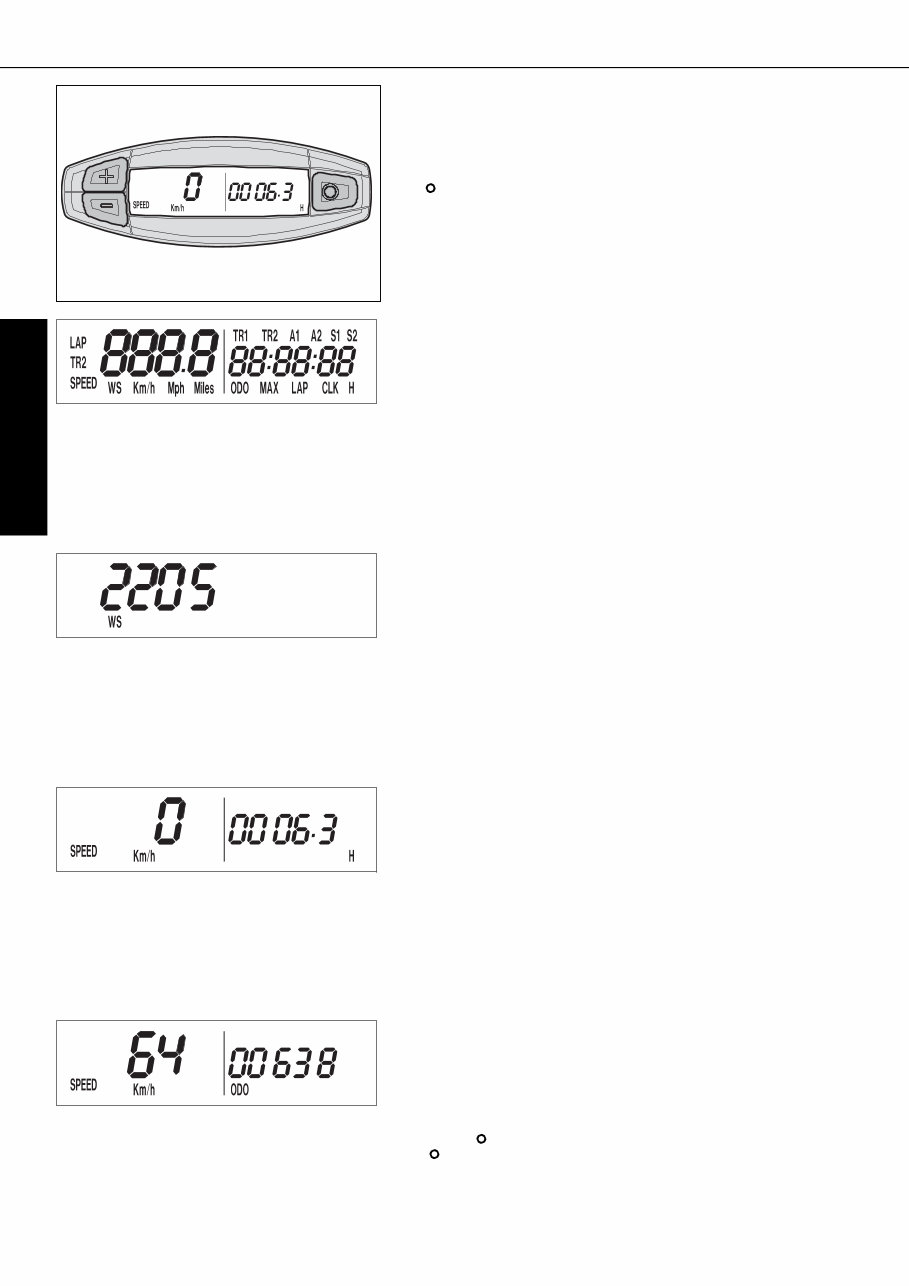
TEST
All of the display segments briefly light up for the display function test.
WS (wheel size)
The display changes and the circumference of the front wheel is briefly dis-
played in millimeters (2205 mm corresponds to a front wheel circumference
of 21" with production tires).
Afterwards the display will return to the previous display mode.
Electronic speedometer
The display in the electronic speedometer is activated as soon as you press
a button on the speedometer or an impulse is received from the wheel sen-
sor. The display lights up when the engine is running.
The display is cleared if no button is pressed for 1 minute or no impulse is
received from the wheel sensor.
The button is used to change between display modes.
The + and – buttons are used to control various functions.
SPEED display mode / H (service hours)
Only the SPEED / H and SPEED / ODO display modes are activated in the
condition at delivery. SPEED/H is displayed whenever the display is activated
and the front wheel is not turning. It automatically changes to the SPEED/ODO
display mode as soon as the front wheel starts turning.
SPEED displays the speed.
H displays the engine's service hours. The service hour counter starts to count
as soon as you start the engine. The displayed figure cannot be changed.
Service intervals are indicated in service hours for some KTM offroad motor-
cycles, making the service hour counter a very practical function.
SPEED / ODO display mode (odometer)
The SPEED/ODO mode displays the speed and the total distance traveled.
The display automatically changes to the SPEED/H display mode when the
front wheel stops turning.
+ button no function
– button no function
briefly press button changes to the next display mode
hold button 3 secs. changes to the next display mode
The electronic speedometer has a number of display modes (functions) that
you can also activate (reveal) (see: Activating and deactivating display modes).
ENGLISH
9
OPERATION INSTRUMENTS »
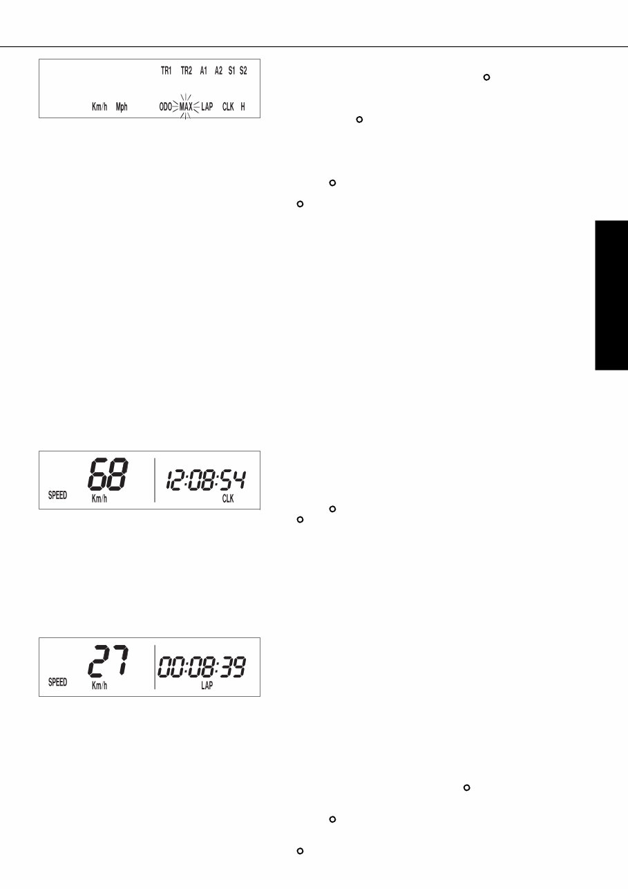
SPEED / LAP (lap time) display mode
You can use the manual stop watch to stop and store up to 10 lap times,
which you can view in the LAP/LAP display mode (see below).
LAP displays the lap times in hours, minutes and seconds.
+ button Starts and stops the stop watch, lap time is not
reset to 0
– button Stops the stop watch, stores the lap time and restarts
the stop watch again. The time is reset to 0. A total
of 10 lap times can be stored. If the lap time con-
tinues to run after you press the - button, all 10 mem-
ory locations are occupied.To clear all of the stored
lap times, hold the button for 3 seconds in the
SPEED/LAP mode.Up to 10 lap times can be stored
in this way.
briefly press button Changes to the next display mode.If no lap time is
stored or the motorcycle is driving, the LAP/LAP
mode will be skipped.
hold button 3 secs. Clears all LAP figures
SPEED / CLK (time) display mode
CLK displays the time in hours, minutes and seconds.
+ button no function
– button no function
briefly press button changes to the next display mode
hold button 3 secs. set the clock menu
To set the clock, see „Setting the clock“.
Activating and deactivating display modes
In the display mode SPEED/H, press and hold the button for 3 seconds to
access the SETUP menu. The active functions will be displayed. The blink-
ing function can be activated by pressing the + button and deactivated by
pressing the – button.
Press and hold the button 3 seconds to store the settings.
If no button is pressed for 20 seconds, the setting will be stored automati-
cally and the display will return to the SPEED/H mode.
+ button activates the blinking display
– button deactivates the blinking display
briefly press button changes to the next display without changing any
settings
hold button 3 secs. starts the SETUP
stores the settings and changes to the SPEED/H
mode
The following display modes can be activated:
TR1 tripmaster 1
TR2 tripmaster 2
A1 average speed 1
A2 average speed 2
S1 stop watch 1
S2 stop watch 2
CLK clock
LAP lap time
MAX maximum speed
KMH/MPH display in kilometers or miles (see: Kilometers or miles)
If you have activated all of the display modes, they will be displayed in the
following order:
SPEED/H, SPEED/CLK, SPEED/LAP, LAP/LAP, SPEED/MAX, SPEED/ODO,
SPEED/TR1, SPEED/TR2, SPEED/A1, SPEED/A2, SPEED/S1, SPEED/S2
You're Reading a Preview
What's Included?
Fast Download Speeds
Online & Offline Access
Access PDF Contents & Bookmarks
Full Search Facility
Print one or all pages of your manual
$31.99
KTM 250-400-450-525 SX-EXC Service Repair Manual 2000-2007
Viewed 65 Times Today

What's Included?
Fast Download Speeds
Online & Offline Access
Access PDF Contents & Bookmarks
Full Search Facility
Print one or all pages of your manual
$31.99

Secure transaction
What's Included?
Fast Download Speeds
Online & Offline Access
Access PDF Contents & Bookmarks
Full Search Facility
Print one or all pages of your manual
Description
The service manual covers repair and service for the following models:
- 250 EXC RACING
- 400 EXC RACING
- 450 SX, MXC, EXC RACING
- 525 SX, MXC, EXC RACING
The manual is applicable for the 2000-2005 models, but it remains the same until 2007.
This is a .OVA file manual, not a print manual, and will be sent on the payment day with 1-day shipping. You will receive the file within 12 hours. It provides fast, affordable service information with free delivery worldwide.


