

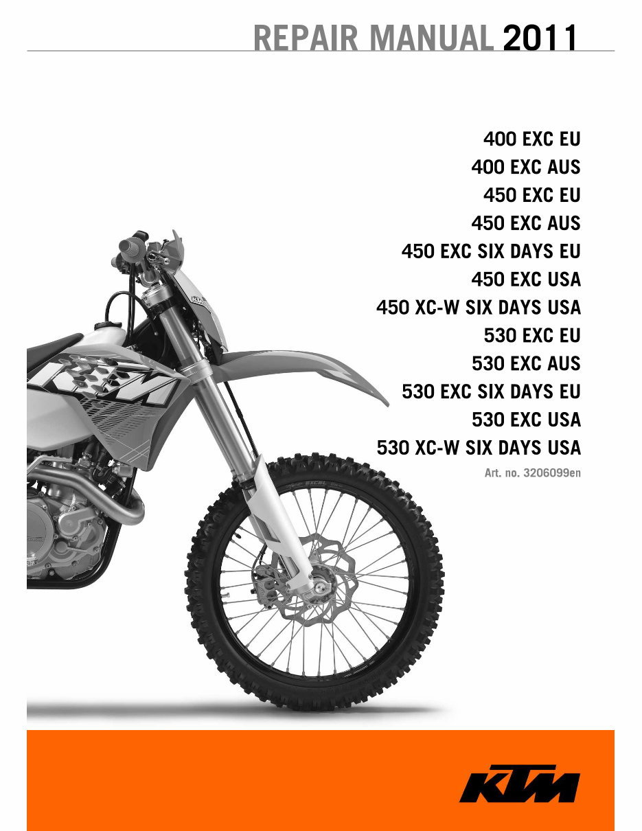
400 EXC EU
400 EXC AUS
450 EXC EU
450 EXC AUS
450 EXC SIX DAYS EU
450 EXC USA
450 XC-W SIX DAYS USA
530 EXC EU
530 EXC AUS
530 EXC SIX DAYS EU
530 EXC USA
530 XC-W SIX DAYS USA
Art. no. 320609gen
400 EXC EU
400 EXC AUS
450 EXC EU
450 EXC AUS
450 EXC SIX DAYS EU
450 EXC USA
450 XC-W SIX DAYS USA
530 EXC EU
530 EXC AUS
530 EXC SIX DAYS EU
530 EXC USA
530 XC-W SIX DAYS USA
Art. no. 320609gen
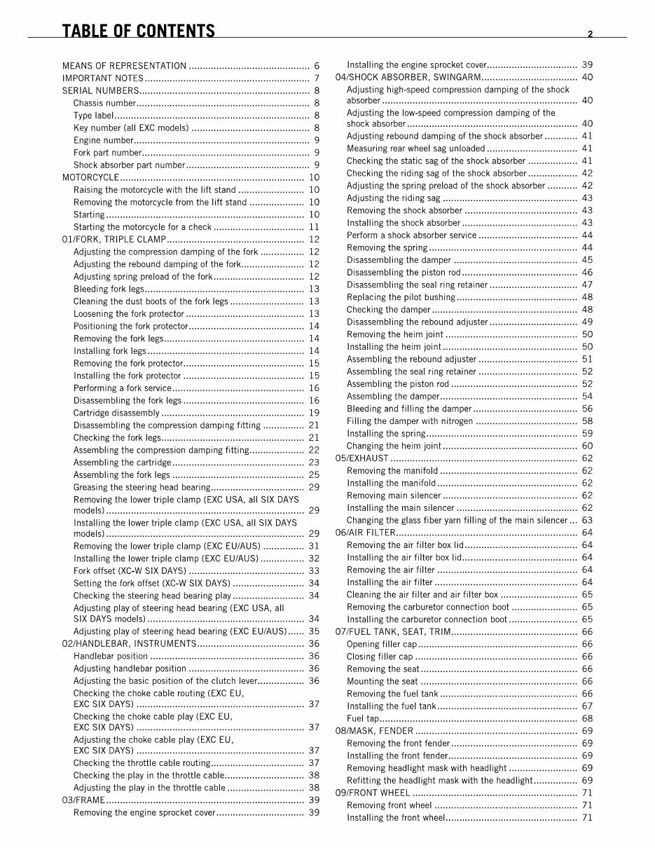
TABLE OF CONTENTS 2
MEANS OF REPRESENTATION ............................................ 6
Installing the engine sprocket cover ................................. 39
IMPORTANT NOTES ............................................................ 7 04/sHOCK ABSORBER, SWINGARM ................................... 40
SERIAL NUMBERS .............................................................. 8
Adjusting high-speed compression damping of the shock
Chassis number ............................................................... 8
absorber.......... ....... .................... .................... .............. 40
Type label ....................................................................... 8
Key number (all EXC models) ........................................... 8
Engine number ................................................................ 9
Fork part number ............................................................. 9
Shock absorber part number ............................................. 9
MOTORCyCLE ................................................................... 10
Adjusting the low-speed compression damping of Ihe
shock absorber .............................................................. 40
Adjusting rebound damping of the shock absorber ............ 41
Measuring rear wheel sag unloaded ................................. 41
Checking the static sag of the shock absorber .................. 41
Checking Ihe riding sag of Ihe shock absorber .................. 42
Raising the motorcycle with the lift stand ........................ 10
Removi ng the motorcycle from the Iift stand .. ....... ....... .... 10
Starting ........................................................................ 10
Starting the motorcycle for a check ................................. 11
OllFORK, TRIPLE CLAMP .................................................. 12
Adjusting the compression damping of the fork ................ 12
Adjusling Ihe rebound damping of Ihe fork ....................... 12
Adjusling spring preload of Ihe fork ................................. 12
Bleeding fork legs .......................................................... 13
Cleaning the dust bools of Ihe fork legs ........................... 13
Loosening the fork protector ........................................... 13
Positioning the fork protector .......................................... 14
Removing the fork legs ................................................... 14
Inslalling fork legs ......................................................... 14
Removing the fork proteclor ............................................ 15
Inslalling Ihe fork protector ............................................ 15
Performing a fork service ................................................ 16
Disassembling the fork legs ............................................ 16
Cartridge disassembly .................................................... 19
Disassembling the compression damping fitting ............... 21
Checking the fork legs .................................................... 21
Assembling Ihe compression damping fitting .................... 22
Assembling Ihe cartridge ................................................ 23
Assembling the fork legs ................................................ 25
Greasing the steering head bearing .................................. 29
Removing the lower triple clamp (EXC USA, all SIX DAYS
models) ........................................................................ 29
Adjusting the spring preload of the shock absorber ........... 42
Adjusting the riding sag ................................................. 43
Removi ng the shock absorber .............. ...... .............. ....... 43
Installing the shock absorber .......................................... 43
Perform a shock absorber service.. ...... ........ ...... .............. 44
Removing the spring ...................................................... 44
Disassembling the damper ............................................. 45
Disassembling the pislon rod .......................................... 46
Disassembling the seal ring retainer ................................ 47
Replacing the pilot bushing ............................................ 48
Checking the damper ..................................................... 48
Disassembling the rebound adjuster ................................ 49
Removing the heim joint ................................................ 50
Installing the heim joint ................................................. 50
Assembling the rebound adjuster .................................... 51
Assembling the seal ring retainer .................................... 52
Assembling the piston rod .............................................. 52
Assembling the damper .................................................. 54
Bleeding and filling the damper ...................................... 56
Filling Ihe damper wilh nitrogen ..................................... 58
Installing the spring ....................................................... 59
Changing the heim joint ................................................. 60
05/EXHAUST .................................................................... 62
Removing the manifold .................................................. 62
Installing the manifold ................................................... 62
Removi ng mai n si lencer .. ...... .............. ...... .............. ....... 62
Installing the main silencer ............................................ 62
Inslalling Ihe lower triple clamp (EXC USA, all SIX DAYS
Changing the glass fiber yarn filling of the main silencer ... 63
models) ........................................................................ 29 06/AIR FILTER .................................................................. 64
Removing the lower triple clamp (EXC EU/AUS) ............... 31 Removing the air filter box lid ......................................... 64
Installing the lower triple clamp (EXC EUiAUS) ................ 32
Installing the air filter box lid .......................................... 64
Fork offset (XC-W SIX DAYS) .......................................... 33
Removing the air filter ................................................... 64
Setting the fork offset (XC-W SIX DAYS) .......................... 34
Installing the air filter .................................................... 64
Checking the steering head bearing play .......................... 34
Cleaning the air filter and air filler box ............................ 65
Adjusling play of steering head bearing (EXC USA, all Removing the carburetor connection boot ........................ 65
SIX DAYS models) ......................................................... 34 Installing the carburetor connection boot ......................... 65
Adjusling play of steering head bearing (EXC EU/AUS) ...... 35 07/FUEL TANK, SEAT, TRIM .............................................. 66
02/HANDLEBAR, INSTRUMENTS ....................................... 36 Opening filler cap .......................................................... 66
Handlebar position ........................................................ 36 Closing filler cap ........................................................... 66
Adjusting handlebar position .......................................... 36 Removi ng the seal... .................... ....... ............. ....... ....... 66
Adjusling the basic position of Ihe clulch lever ................. 36 Mounting the seal ......................................................... 66
Checking the choke cable routing (EXC EU, Removing the fuel tank .................................................. 66
EXC SIX DAYS) ............................................................. 37
Installing the fuel tank ................................................... 67
Checking the choke cable play (EXC EU,
EXC SIX DAYS) ............................................................. 37
Fuel tap ........................................................................ 68
08!MASK, FENDER ........................................................... 69
Adjusting the choke cable play (EXC EU,
EXC SIX DAYS) ............................................................. 37
Checking the throttle cable routing .................................. 37
Checking the play in Ihe throttle cable ............................. 38
Adjusling the play in the throttle cable ............................ 38
03/FRAM E...... .................... .................... .................... ...... 39
Removing the engine sprocket cover ................................ 39
Removi ng the front fender ............ ...... .............. ...... ........ 69
Install i ng the front fender...... ...... ........ ...... ...... ........ ....... 69
Removing headlight mask with headlight ......................... 69
Refitting the headlight mask with the headlight. ............... 69
09/FRONT WHEEL ............................................................ 71
Removi ng front wheel.... .............. ...... .............. ...... ........ 71
Install i ng the front wheeL...... ...... ........ ...... ...... ........ ....... 71
TABLE OF CONTENTS 2
MEANS OF REPRESENTATION ............................................ 6
Installing the engine sprocket cover ................................. 39
IMPORTANT NOTES ............................................................ 7 04/sHOCK ABSORBER, SWINGARM ................................... 40
SERIAL NUMBERS .............................................................. 8
Adjusting high-speed compression damping of the shock
Chassis number ............................................................... 8
absorber.......... ....... .................... .................... .............. 40
Type label ....................................................................... 8
Key number (all EXC models) ........................................... 8
Engine number ................................................................ 9
Fork part number ............................................................. 9
Shock absorber part number ............................................. 9
MOTORCyCLE ................................................................... 10
Adjusting the low-speed compression damping of Ihe
shock absorber .............................................................. 40
Adjusting rebound damping of the shock absorber ............ 41
Measuring rear wheel sag unloaded ................................. 41
Checking the static sag of the shock absorber .................. 41
Checking Ihe riding sag of Ihe shock absorber .................. 42
Raising the motorcycle with the lift stand ........................ 10
Removi ng the motorcycle from the Iift stand .. ....... ....... .... 10
Starting ........................................................................ 10
Starting the motorcycle for a check ................................. 11
OllFORK, TRIPLE CLAMP .................................................. 12
Adjusting the compression damping of the fork ................ 12
Adjusling Ihe rebound damping of Ihe fork ....................... 12
Adjusling spring preload of Ihe fork ................................. 12
Bleeding fork legs .......................................................... 13
Cleaning the dust bools of Ihe fork legs ........................... 13
Loosening the fork protector ........................................... 13
Positioning the fork protector .......................................... 14
Removing the fork legs ................................................... 14
Inslalling fork legs ......................................................... 14
Removing the fork proteclor ............................................ 15
Inslalling Ihe fork protector ............................................ 15
Performing a fork service ................................................ 16
Disassembling the fork legs ............................................ 16
Cartridge disassembly .................................................... 19
Disassembling the compression damping fitting ............... 21
Checking the fork legs .................................................... 21
Assembling Ihe compression damping fitting .................... 22
Assembling Ihe cartridge ................................................ 23
Assembling the fork legs ................................................ 25
Greasing the steering head bearing .................................. 29
Removing the lower triple clamp (EXC USA, all SIX DAYS
models) ........................................................................ 29
Adjusting the spring preload of the shock absorber ........... 42
Adjusting the riding sag ................................................. 43
Removi ng the shock absorber .............. ...... .............. ....... 43
Installing the shock absorber .......................................... 43
Perform a shock absorber service.. ...... ........ ...... .............. 44
Removing the spring ...................................................... 44
Disassembling the damper ............................................. 45
Disassembling the pislon rod .......................................... 46
Disassembling the seal ring retainer ................................ 47
Replacing the pilot bushing ............................................ 48
Checking the damper ..................................................... 48
Disassembling the rebound adjuster ................................ 49
Removing the heim joint ................................................ 50
Installing the heim joint ................................................. 50
Assembling the rebound adjuster .................................... 51
Assembling the seal ring retainer .................................... 52
Assembling the piston rod .............................................. 52
Assembling the damper .................................................. 54
Bleeding and filling the damper ...................................... 56
Filling Ihe damper wilh nitrogen ..................................... 58
Installing the spring ....................................................... 59
Changing the heim joint ................................................. 60
05/EXHAUST .................................................................... 62
Removing the manifold .................................................. 62
Installing the manifold ................................................... 62
Removi ng mai n si lencer .. ...... .............. ...... .............. ....... 62
Installing the main silencer ............................................ 62
Inslalling Ihe lower triple clamp (EXC USA, all SIX DAYS
Changing the glass fiber yarn filling of the main silencer ... 63
models) ........................................................................ 29 06/AIR FILTER .................................................................. 64
Removing the lower triple clamp (EXC EU/AUS) ............... 31 Removing the air filter box lid ......................................... 64
Installing the lower triple clamp (EXC EUiAUS) ................ 32
Installing the air filter box lid .......................................... 64
Fork offset (XC-W SIX DAYS) .......................................... 33
Removing the air filter ................................................... 64
Setting the fork offset (XC-W SIX DAYS) .......................... 34
Installing the air filter .................................................... 64
Checking the steering head bearing play .......................... 34
Cleaning the air filter and air filler box ............................ 65
Adjusling play of steering head bearing (EXC USA, all Removing the carburetor connection boot ........................ 65
SIX DAYS models) ......................................................... 34 Installing the carburetor connection boot ......................... 65
Adjusling play of steering head bearing (EXC EU/AUS) ...... 35 07/FUEL TANK, SEAT, TRIM .............................................. 66
02/HANDLEBAR, INSTRUMENTS ....................................... 36 Opening filler cap .......................................................... 66
Handlebar position ........................................................ 36 Closing filler cap ........................................................... 66
Adjusting handlebar position .......................................... 36 Removi ng the seal... .................... ....... ............. ....... ....... 66
Adjusling the basic position of Ihe clulch lever ................. 36 Mounting the seal ......................................................... 66
Checking the choke cable routing (EXC EU, Removing the fuel tank .................................................. 66
EXC SIX DAYS) ............................................................. 37
Installing the fuel tank ................................................... 67
Checking the choke cable play (EXC EU,
EXC SIX DAYS) ............................................................. 37
Fuel tap ........................................................................ 68
08!MASK, FENDER ........................................................... 69
Adjusting the choke cable play (EXC EU,
EXC SIX DAYS) ............................................................. 37
Checking the throttle cable routing .................................. 37
Checking the play in Ihe throttle cable ............................. 38
Adjusling the play in the throttle cable ............................ 38
03/FRAM E...... .................... .................... .................... ...... 39
Removing the engine sprocket cover ................................ 39
Removi ng the front fender ............ ...... .............. ...... ........ 69
Install i ng the front fender...... ...... ........ ...... ...... ........ ....... 69
Removing headlight mask with headlight ......................... 69
Refitting the headlight mask with the headlight. ............... 69
09/FRONT WHEEL ............................................................ 71
Removi ng front wheel.... .............. ...... .............. ...... ........ 71
Install i ng the front wheeL...... ...... ........ ...... ...... ........ ....... 71
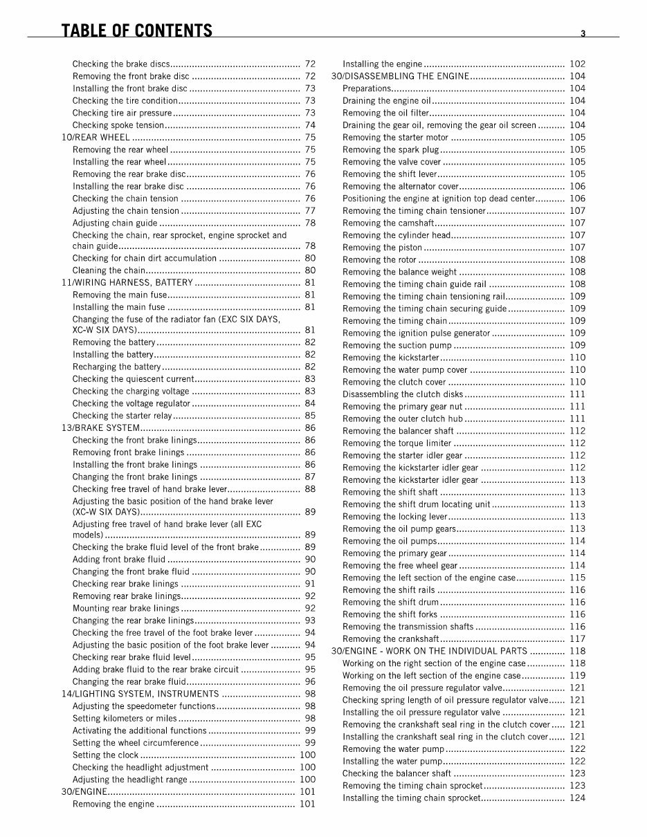
TABLE OF CONTENTS 3
Checking the brake discs ................................................ 72 Installing the engine .................................................... 102
Removing the Iront brake disc ........................................ 72 3D/DISASSEMBLING THE ENGINE ................................... 104
Installing the front brake disc ......................................... 73 Preparations ................................................................ 104
Checking the tire condition ............................................. 73 Draining the engine oil ................................................. 104
Checking tire air pressure ............................................... 73 Removing the oil lilter.................................................. 104
Checking spoke tension .................................................. 74 Draining the gear oil, removing the gear oil screen .......... 104
lO/REAR WHEEL .............................................................. 75 Removi ng the starter motor.......... ...... .............. ....... ..... 105
Removing the rear wheel ................................................ 75 Removi ng the spark pi ug .............. ...... .............. ...... ...... 105
Installing the rear wheel ................................................. 75 Removing the valve cover ............................................. 105
Removing the rear brake disc .......................................... 76 Removing the shift lever ............................................... 105
Installing the rear brake disc .......................................... 76 Removi ng the alternator cover. ....... ...... ....... ....... ...... ..... 106
Checking the chain tension ............................................ 76 Positioning the engine at ignition top dead center ........... 106
Adjusting the chain tension ............................................ 77 Removing the timing chain tensioner ............................. 107
Adjusting chain guide .................................................... 78 Removing the camshaft ................................................ 107
Checking the chain, rear sprocket, engine sprocket and Removing the cylinder head .......................................... 107
chain guide ................................................................... 78
Removing the piston .................................................... 107
Checking for chain dirt accumulation .............................. 80
Removi ng the rotor.. ...... .............. ...... .............. ....... ..... 108
Clean i ng the chai n.... .............. ...... .............. ...... ............. 80
Removing the balance weight ....................................... 108
11IWIRING HARNESS, BATTERy ....................................... 81
Removing the timing chain guide rail ............................ 108
Removing the main fuse ................................................. 81
Removing the timing chain tensioning rail .. .................... 109
Installing the main fuse ................................................. 81
Removing the timing chain securing guide ..................... 109
Changing the fuse of the radiator Ian (EXC SIX DAYS,
Removing the timing chain ........................................... 109
XC-W SIX DAYS) ............................................................ 81
Removing the ignition pulse generator ........................... 109
Removi ng the battery .............. ...... .............. ...... ............. 82
Removing the suction pump ......................................... 109
Installing the battery ...................................................... 82
Removing the kickstarter .............................................. 110
Rechargi ng the battery ............ ...... .............. ...... ............. 82
Removing the water pump cover ................................... 110
Checking the quiescent current ....................................... 83
Removi ng the cl utch cover .... .............. ...... .............. ..... 11 0
Checking the charging voltage ........................................ 83
Disassembling the clutch disks ..................................... 111
Checking the voltage regulator ........................................ 84
Removi ng the pri mary gear nut ............ ...... .............. ..... 111
Checking the starter relay ............................................... 85
Removing the outer clutch hub ..................................... 111
13/BRAKE SYSTEM ........................................................... 86
Removing the balancer shaft ........................................ 112
Checking the front brake linings ...................................... 86
Removing the torque limiter ......................................... 112
Removing front brake linings .......................................... 86
Removing the starter idler gear ..................................... 112
Installing the front brake linings ..................................... 86
Removing the kickstarter idler gear ............................... 112
Changing the front brake linings ..................................... 87
Removing the kickstarter idler gear ............................... 113
Checking free travel of hand brake lever ........................... 88
Removing the shift shaft .............................................. 113
Adjusting the basic position of the hand brake lever
(XC-W SIX DAyS) ........................................................... 89
Adjusting free travel of hand brake lever (all EXC
models) ........................................................................ 89
Checking the brake Iluid level of the Iront brake ............... 89
Adding Iront brake Iluid ................................................. 90
Changing the Iront brake Iluid ........................................ 90
Checking rear brake linings ............................................ 91
Removing rear brake linings............................................ 92
Mounting rear brake linings ............................................ 92
Changing the rear brake linings ....................................... 93
Checking the Iree travel of the loot brake lever ................. 94
Adjusting the basic position 01 the loot brake lever ........... 94
Checking rear brake Iluid level ........................................ 95
Adding brake fluid to the rear brake circuit ...................... 95
Changing the rear brake Iluid .......................................... 96
14/LiGHTING SYSTEM, INSTRUMENTS ............................. 98
Adjusting the speedometer lunctions ............................... 98
Setting kilometers or miles ............................................. 98
Activating the additional lunctions .................................. 99
Setting the wheel circumference ..................................... 99
Setting the clock ......................................................... 100
Checking the headlight adjustment ............................... 100
Adjusting the headlight range ....................................... 100
3D/ENGINE ..................................................................... 101
Removing the engine ................................................... 101
Removing the shift drum locating unit ........................... 113
Removing the locking lever ........................................... 113
Removing the oil pump gears ........................................ 113
Removing the oil pumps ............................................... 114
Removing the primary gear ........................................... 114
Removing the Iree wheel gear ....................................... 114
Removi ng the left section 01 the engi ne case ...... ............ 115
Removing the shift rails ............................................... 116
Removing the shift drum .............................................. 116
Removing the shift lorks .............................................. 116
Removing the transmission shafts ................................. 116
Removing the crankshaft .............................................. 117
3D/ENGINE - WORK ON THE INDIVIDUAL PARTS ............. 118
Working on the right section of the engine case .............. 118
Working on the left section of the engine case ................ 119
Removing the oil pressure regulator valve ....................... 121
Checking spring length of oil pressure regulator valve ...... 121
Installing the oil pressure regulator valve ....................... 121
Removing the crankshaft seal ring in the clutch cover ..... 121
Installing the crankshaft seal ring in the clutch cover ...... 121
Removing the water pump ............................................ 122
Installing the water pump ............................................. 122
Checking the balancer shaft ......................................... 123
Removing the timing chain sprocket .............................. 123
Installing the timing chain sprocket ............................... 124
TABLE OF CONTENTS 3
Checking the brake discs ................................................ 72 Installing the engine .................................................... 102
Removing the Iront brake disc ........................................ 72 3D/DISASSEMBLING THE ENGINE ................................... 104
Installing the front brake disc ......................................... 73 Preparations ................................................................ 104
Checking the tire condition ............................................. 73 Draining the engine oil ................................................. 104
Checking tire air pressure ............................................... 73 Removing the oil lilter.................................................. 104
Checking spoke tension .................................................. 74 Draining the gear oil, removing the gear oil screen .......... 104
lO/REAR WHEEL .............................................................. 75 Removi ng the starter motor.......... ...... .............. ....... ..... 105
Removing the rear wheel ................................................ 75 Removi ng the spark pi ug .............. ...... .............. ...... ...... 105
Installing the rear wheel ................................................. 75 Removing the valve cover ............................................. 105
Removing the rear brake disc .......................................... 76 Removing the shift lever ............................................... 105
Installing the rear brake disc .......................................... 76 Removi ng the alternator cover. ....... ...... ....... ....... ...... ..... 106
Checking the chain tension ............................................ 76 Positioning the engine at ignition top dead center ........... 106
Adjusting the chain tension ............................................ 77 Removing the timing chain tensioner ............................. 107
Adjusting chain guide .................................................... 78 Removing the camshaft ................................................ 107
Checking the chain, rear sprocket, engine sprocket and Removing the cylinder head .......................................... 107
chain guide ................................................................... 78
Removing the piston .................................................... 107
Checking for chain dirt accumulation .............................. 80
Removi ng the rotor.. ...... .............. ...... .............. ....... ..... 108
Clean i ng the chai n.... .............. ...... .............. ...... ............. 80
Removing the balance weight ....................................... 108
11IWIRING HARNESS, BATTERy ....................................... 81
Removing the timing chain guide rail ............................ 108
Removing the main fuse ................................................. 81
Removing the timing chain tensioning rail .. .................... 109
Installing the main fuse ................................................. 81
Removing the timing chain securing guide ..................... 109
Changing the fuse of the radiator Ian (EXC SIX DAYS,
Removing the timing chain ........................................... 109
XC-W SIX DAYS) ............................................................ 81
Removing the ignition pulse generator ........................... 109
Removi ng the battery .............. ...... .............. ...... ............. 82
Removing the suction pump ......................................... 109
Installing the battery ...................................................... 82
Removing the kickstarter .............................................. 110
Rechargi ng the battery ............ ...... .............. ...... ............. 82
Removing the water pump cover ................................... 110
Checking the quiescent current ....................................... 83
Removi ng the cl utch cover .... .............. ...... .............. ..... 11 0
Checking the charging voltage ........................................ 83
Disassembling the clutch disks ..................................... 111
Checking the voltage regulator ........................................ 84
Removi ng the pri mary gear nut ............ ...... .............. ..... 111
Checking the starter relay ............................................... 85
Removing the outer clutch hub ..................................... 111
13/BRAKE SYSTEM ........................................................... 86
Removing the balancer shaft ........................................ 112
Checking the front brake linings ...................................... 86
Removing the torque limiter ......................................... 112
Removing front brake linings .......................................... 86
Removing the starter idler gear ..................................... 112
Installing the front brake linings ..................................... 86
Removing the kickstarter idler gear ............................... 112
Changing the front brake linings ..................................... 87
Removing the kickstarter idler gear ............................... 113
Checking free travel of hand brake lever ........................... 88
Removing the shift shaft .............................................. 113
Adjusting the basic position of the hand brake lever
(XC-W SIX DAyS) ........................................................... 89
Adjusting free travel of hand brake lever (all EXC
models) ........................................................................ 89
Checking the brake Iluid level of the Iront brake ............... 89
Adding Iront brake Iluid ................................................. 90
Changing the Iront brake Iluid ........................................ 90
Checking rear brake linings ............................................ 91
Removing rear brake linings............................................ 92
Mounting rear brake linings ............................................ 92
Changing the rear brake linings ....................................... 93
Checking the Iree travel of the loot brake lever ................. 94
Adjusting the basic position 01 the loot brake lever ........... 94
Checking rear brake Iluid level ........................................ 95
Adding brake fluid to the rear brake circuit ...................... 95
Changing the rear brake Iluid .......................................... 96
14/LiGHTING SYSTEM, INSTRUMENTS ............................. 98
Adjusting the speedometer lunctions ............................... 98
Setting kilometers or miles ............................................. 98
Activating the additional lunctions .................................. 99
Setting the wheel circumference ..................................... 99
Setting the clock ......................................................... 100
Checking the headlight adjustment ............................... 100
Adjusting the headlight range ....................................... 100
3D/ENGINE ..................................................................... 101
Removing the engine ................................................... 101
Removing the shift drum locating unit ........................... 113
Removing the locking lever ........................................... 113
Removing the oil pump gears ........................................ 113
Removing the oil pumps ............................................... 114
Removing the primary gear ........................................... 114
Removing the Iree wheel gear ....................................... 114
Removi ng the left section 01 the engi ne case ...... ............ 115
Removing the shift rails ............................................... 116
Removing the shift drum .............................................. 116
Removing the shift lorks .............................................. 116
Removing the transmission shafts ................................. 116
Removing the crankshaft .............................................. 117
3D/ENGINE - WORK ON THE INDIVIDUAL PARTS ............. 118
Working on the right section of the engine case .............. 118
Working on the left section of the engine case ................ 119
Removing the oil pressure regulator valve ....................... 121
Checking spring length of oil pressure regulator valve ...... 121
Installing the oil pressure regulator valve ....................... 121
Removing the crankshaft seal ring in the clutch cover ..... 121
Installing the crankshaft seal ring in the clutch cover ...... 121
Removing the water pump ............................................ 122
Installing the water pump ............................................. 122
Checking the balancer shaft ......................................... 123
Removing the timing chain sprocket .............................. 123
Installing the timing chain sprocket ............................... 124
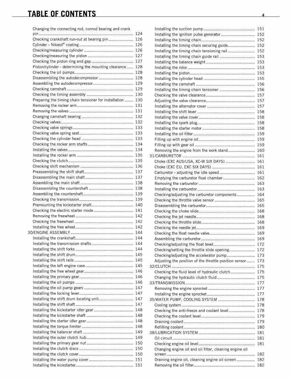
TABLE OF CONTENTS 4
Changing the connecting rod, conrad bearing and crank Installing the suction pump .......................................... 151
pin ............................................................................. 124
Installing the ignition pulse generator ............................ 152
Checking crankshaft run-out at bearing pin .................... 126
Installing the timing chain ............................................ 152
Cylinder - Nikasil" coating ............................................ 126
Installing the timing chain securing guide ...................... 152
Checking/measuring cylinder ........................................ 126
Installing the timing chain tensioning rail ...................... 152
Checking/measuring the piston ..................................... 127
Installing the timing chain guide rail ............................. 153
Checking the piston ring end gap .................................. 127
Installing the balance weight ........................................ 153
Piston/cylinder - determining the mounting clearance ..... 128
Installing the rotor ....................................................... 153
Checking the oil pumps ................................................ 128
Installing the piston ..................................................... 153
Disassembling the autodecompressor ............................ 128
Installing the cylinder head .......................................... 155
Assembling the autodecompressor ................................. 129
Installing the camshaft ................................................ 156
Checking camshaft ...................................................... 129
Installing the timing chain tensioner ............................. 156
Checking the timing assembly ...................................... 130
Checking the valve clearance ........................................ 157
Preparing the timing chain tensioner for installation ....... 130
Adjusting the valve clearance ........................................ 157
Removing the rocker arm .............................................. 131
Installing the alternator cover ....................................... 157
Removing the valves .................................................... 131
Installing the shift lever ............................................... 158
Changing camshaft bearing .......................................... 132
Installing the valve cover .............................................. 158
Checking valves ........................................................... 132
Installing the spark plug ............................................... 158
Checking valve springs ................................................. 133
Installing the starter motor ........................................... 158
Checking valve spring seat ............................................ 133
Installing the oil filter .................................................. 159
Checking the cylinder head .......................................... 133
Filling up with engine oil .............................................. 159
Checking the rocker arm shafts ..................................... 134
Filling up with gear oil ................................................. 159
Installing the valves ..................................................... 134
Removing the engine from the work stand ...................... 160
Installing the rocker arm .............................................. 135
31/CARBURETOR ........................................................... 161
Checking the clutch ..................................................... 135
Choke (EXC AUS/USA, XC.W SIX DAYS) ........................ 161
Checking shift mechanism ........................................... 136
Choke (EXC EU, EXC SIX DAYS) ................................... 161
Preassembling the shift shaft ........................................ 137
Carburetor - adjusting the idle speed ............................. 161
Disassembling the main shaft ....................................... 137
Emptying the carburetor float chamber .......................... 162
Assembling the main shaft ........................................... 138
Removing the carburetor .............................................. 163
Disassembling the countershaft .................................... 138
Installing the carburetor ............................................... 163
Assembling the countershaft ......................................... 139
Checking/adjusting the carburetor components ............... 164
Checking the transmission ............................................ 139
Checking the throttle valve sensor ................................. 165
Premounting the kickstarter shaft .................................. 140
Disassembling the carburetor ........................................ 165
Checking the electric starter mode ................................ 141
Checking the choke slide .............................................. 168
Removing the freewheel ............................................... 142
Checking the jet needle................................................ 168
Checking the freewheel ................................................ 142
Checking the throttle slide ............................................ 168
Installing the free wheel ............................................... 142
Checking the needle jet ................................................ 169
30/ENGINE ASSEMBLy ................................................... 144
Checking the float needle valve ..................................... 169
Installing the crankshaft ............................................... 144
Assembling the carburetor ............................................ 169
Installing the transmission shafts .................................. 144
Checking/adjusting the float level .................................. 172
Installing the shift forks ............................................... 144
Checking/setting the throttle slide opening ..................... 172
Installing the shift drum ............................................... 145
Checking/adjusting the accelerator pump ....................... 173
Installing the shift rails ................................................ 145
Adjusting the position of the throttle position sensor ....... 173
Installing the left engine case ....................................... 145
321CLUTCH .................................................................... 175
Installing the free wheel gear ........................................ 146
Checking the fluid level of hydraulic clutch .................... 175
Installing the primary gear ............................................ 146
Changing the hydraulic clutch fluid ............................... 175
Installing the oil pumps ............................................... 146
33fTRANSMISSION ......................................................... 177
Installing the oil pump gears ........................................ 147
Removing the engine sprocket ...................................... 177
Installing the locking lever............................................ 147
Installing the engine sprocket ....................................... 177
Installing the shift drum locating uni! .. .......................... 147
35IWATER PUMP, COOLING SYSTEM .............................. 178
Installing the shift shaft ............................................... 147
Cooling system ............................................................ 178
Installing the kickstarter idler gear ................................ 148
Checking the anti-freeze and coolant level ..................... 178
Installing the kickstarter shaft ...................................... 148
Checking the coolant level ............................................ 179
Installing the starter idler gear ...................................... 148
Draining coolant .......................................................... 179
Installing the torque limiter .......................................... 148
Refilling coolant .......................................................... 180
Installing the balancer shaft ......................................... 149
381LUBRICATION SYSTEM .............................................. 181
Installing the outer clutch hub ...................................... 149
Oil circuit ................................................................... 181
Installing the primary gear nut ...................................... 150
Checking engine oil level .............................................. 181
Installing the clutch discs ............................................ 150
Changing engine oil and oil filter, cleaning engine oil
Installing the clutch cover ............................................ 150 screen ........................................................................ 182
Installing the water pump cover .................................... 151 Draining engine oil, cleaning engine oil screen ............... 182
Installing the kickstarter ............................................... 151 Removing the oil filter .................................................. 182
TABLE OF CONTENTS 4
Changing the connecting rod, conrad bearing and crank Installing the suction pump .......................................... 151
pin ............................................................................. 124
Installing the ignition pulse generator ............................ 152
Checking crankshaft run-out at bearing pin .................... 126
Installing the timing chain ............................................ 152
Cylinder - Nikasil" coating ............................................ 126
Installing the timing chain securing guide ...................... 152
Checking/measuring cylinder ........................................ 126
Installing the timing chain tensioning rail ...................... 152
Checking/measuring the piston ..................................... 127
Installing the timing chain guide rail ............................. 153
Checking the piston ring end gap .................................. 127
Installing the balance weight ........................................ 153
Piston/cylinder - determining the mounting clearance ..... 128
Installing the rotor ....................................................... 153
Checking the oil pumps ................................................ 128
Installing the piston ..................................................... 153
Disassembling the autodecompressor ............................ 128
Installing the cylinder head .......................................... 155
Assembling the autodecompressor ................................. 129
Installing the camshaft ................................................ 156
Checking camshaft ...................................................... 129
Installing the timing chain tensioner ............................. 156
Checking the timing assembly ...................................... 130
Checking the valve clearance ........................................ 157
Preparing the timing chain tensioner for installation ....... 130
Adjusting the valve clearance ........................................ 157
Removing the rocker arm .............................................. 131
Installing the alternator cover ....................................... 157
Removing the valves .................................................... 131
Installing the shift lever ............................................... 158
Changing camshaft bearing .......................................... 132
Installing the valve cover .............................................. 158
Checking valves ........................................................... 132
Installing the spark plug ............................................... 158
Checking valve springs ................................................. 133
Installing the starter motor ........................................... 158
Checking valve spring seat ............................................ 133
Installing the oil filter .................................................. 159
Checking the cylinder head .......................................... 133
Filling up with engine oil .............................................. 159
Checking the rocker arm shafts ..................................... 134
Filling up with gear oil ................................................. 159
Installing the valves ..................................................... 134
Removing the engine from the work stand ...................... 160
Installing the rocker arm .............................................. 135
31/CARBURETOR ........................................................... 161
Checking the clutch ..................................................... 135
Choke (EXC AUS/USA, XC.W SIX DAYS) ........................ 161
Checking shift mechanism ........................................... 136
Choke (EXC EU, EXC SIX DAYS) ................................... 161
Preassembling the shift shaft ........................................ 137
Carburetor - adjusting the idle speed ............................. 161
Disassembling the main shaft ....................................... 137
Emptying the carburetor float chamber .......................... 162
Assembling the main shaft ........................................... 138
Removing the carburetor .............................................. 163
Disassembling the countershaft .................................... 138
Installing the carburetor ............................................... 163
Assembling the countershaft ......................................... 139
Checking/adjusting the carburetor components ............... 164
Checking the transmission ............................................ 139
Checking the throttle valve sensor ................................. 165
Premounting the kickstarter shaft .................................. 140
Disassembling the carburetor ........................................ 165
Checking the electric starter mode ................................ 141
Checking the choke slide .............................................. 168
Removing the freewheel ............................................... 142
Checking the jet needle................................................ 168
Checking the freewheel ................................................ 142
Checking the throttle slide ............................................ 168
Installing the free wheel ............................................... 142
Checking the needle jet ................................................ 169
30/ENGINE ASSEMBLy ................................................... 144
Checking the float needle valve ..................................... 169
Installing the crankshaft ............................................... 144
Assembling the carburetor ............................................ 169
Installing the transmission shafts .................................. 144
Checking/adjusting the float level .................................. 172
Installing the shift forks ............................................... 144
Checking/setting the throttle slide opening ..................... 172
Installing the shift drum ............................................... 145
Checking/adjusting the accelerator pump ....................... 173
Installing the shift rails ................................................ 145
Adjusting the position of the throttle position sensor ....... 173
Installing the left engine case ....................................... 145
321CLUTCH .................................................................... 175
Installing the free wheel gear ........................................ 146
Checking the fluid level of hydraulic clutch .................... 175
Installing the primary gear ............................................ 146
Changing the hydraulic clutch fluid ............................... 175
Installing the oil pumps ............................................... 146
33fTRANSMISSION ......................................................... 177
Installing the oil pump gears ........................................ 147
Removing the engine sprocket ...................................... 177
Installing the locking lever............................................ 147
Installing the engine sprocket ....................................... 177
Installing the shift drum locating uni! .. .......................... 147
35IWATER PUMP, COOLING SYSTEM .............................. 178
Installing the shift shaft ............................................... 147
Cooling system ............................................................ 178
Installing the kickstarter idler gear ................................ 148
Checking the anti-freeze and coolant level ..................... 178
Installing the kickstarter shaft ...................................... 148
Checking the coolant level ............................................ 179
Installing the starter idler gear ...................................... 148
Draining coolant .......................................................... 179
Installing the torque limiter .......................................... 148
Refilling coolant .......................................................... 180
Installing the balancer shaft ......................................... 149
381LUBRICATION SYSTEM .............................................. 181
Installing the outer clutch hub ...................................... 149
Oil circuit ................................................................... 181
Installing the primary gear nut ...................................... 150
Checking engine oil level .............................................. 181
Installing the clutch discs ............................................ 150
Changing engine oil and oil filter, cleaning engine oil
Installing the clutch cover ............................................ 150 screen ........................................................................ 182
Installing the water pump cover .................................... 151 Draining engine oil, cleaning engine oil screen ............... 182
Installing the kickstarter ............................................... 151 Removing the oil filter .................................................. 182
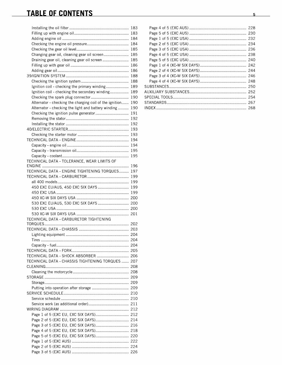
TABLE OF CONTENTS 5
Installing the oil filte, .................................................. 183 Page 4 of 5 (EXC AUS) ................................................ 228
Filling up with engine oil .............................................. 183 Page 5 of 5 (EXC AUS) ................................................ 230
Adding engine oil ........................................................ 184 Page 1 of 5 (EXC USA) ................................................ 232
Checking the engine oil p'essu'e ................................... 184 Page 2 of 5 (EXC USA) ................................................ 234
Checking the gea, oil leveL ........................................... 185 Page 3 of 5 (EXC USA) ................................................ 236
Changing gear oil, cleaning gear oil screen ..................... 185 Page 4 of 5 (EXC USA) ................................................ 238
Draining gear oil, cleaning gear oil screen ...................... 185 Page 5 of 5 (EXC USA) ................................................ 240
Filling up with gea, oil ................................................. 186 Page 1 of 4 (XC-W SIX DAYS) ....................................... 242
Adding gea, oil ............................................................ 186 Page 2 of 4 (XC-W SIX DAYS) ....................................... 244
39/1GNITION SYSTEM ..................................................... 188 Page 3 of 4 (XC-W SIX DAYS) ....................................... 246
Checking the ignition system ........................................ 188 Page 4 of 4 (XC-W SIX DAYS) ....................................... 248
Ignition coil - checking the p,imary winding ................... 189 SUBSTANCES ................................................................. 250
Ignition coil - checking the secondary winding ................ 189 AUXILIARY SUBSTANCES ................................................ 252
Checking the spa,k plug connecto' ................................ 190 SPECIAL TOOLS .............................................................. 254
Alternato, - checking the cha,ging coil of the ignition ...... 190 STANDARDS ................................................................... 267
Alternato, - checking the light and battery winding ......... 190 INDEX ............................................................................ 268
Checking the ignition pulse gene,ato, ............................ 191
Removi ng the stato,... ....... ....... ...... ....... ....... ...... .......... 192
Installing the stato, ..................................................... 192
40/ELECTRIC STARTER ................................................... 193
Checking the starte' mota, ........................................... 193
TECHNICAL DATA - ENGINE ............................................ 194
Gapacity - engine oil .................................................... 194
Gapacity - transmission oiL ........................................... 195
Gapacity - coolant ........................................................ 195
TECHNICAL DATA - TOLERANCE, WEAR LIMITS OF
ENGINE ......................................................................... 196
TECHNICAL DATA - ENGINE TIGHTENING TORQUES ........ 197
TECHNICAL DATA - CARBURETOR ................................... 199
all 400 models ............................................................ 199
450 EXC EU/AUS, 450 EXC SIX DAYS .......................... 199
450 EXC USA ............................................................. 199
450 XC-W SIX DAYS USA ............................................ 200
530 EXC EU/AUS, 530 EXC SIX DAYS .......................... 200
530 EXC USA ............................................................. 200
530 XC-W SIX DAYS USA ............................................ 201
TECHNICAL DATA - CARBURETOR TIGHTENING
TORQU ES ....... .................... .................... ........................ 202
TECHNICAL DATA - CHASSIS .......................................... 203
Lighting equipment ..................................................... 204
Ti,es .......................................................................... 204
Gapacity - fuel.... ...... .............. ...... .............. ...... ........... 204
TECHNICAL DATA - FORK ................................................ 205
TECHNICAL DATA - SHOCK ABSORBER ........................... 206
TECHNICAL DATA - CHASSIS TIGHTENING TORQUES ...... 207
CLEAN I NG...... .................... ....... ............. ....... ................. 208
Clean i ng the motorcycle................. ....... ............. .......... 208
STORAGE ....................................................................... 209
Sto'age ....................................................................... 209
Putting into ope,ation afie, sto,age ............................... 209
SERVICE SCHEDULE ....................................................... 210
Service schedule ......................................................... 210
Service wo,k (as additional o'de') .................................. 211
WIRING DIAGRAM .......................................................... 212
Page 1 of 5 (EXC EU, EXC SIX DAyS) ............................ 212
Page 2 of 5 (EXC EU, EXC SIX DAyS) ............................ 214
Page 3 of 5 (EXC EU, EXC SIX DAyS) ............................ 216
Page 4 of 5 (EXC EU, EXC SIX DAyS) ............................ 218
Page 5 of 5 (EXC EU, EXC SIX DAyS) ............................ 220
Page 1 of 5 (EXC AUS) ................................................ 222
Page 2 of 5 (EXC AUS) ................................................ 224
Page 3 of 5 (EXC AUS) ................................................ 226
TABLE OF CONTENTS 5
Installing the oil filte, .................................................. 183 Page 4 of 5 (EXC AUS) ................................................ 228
Filling up with engine oil .............................................. 183 Page 5 of 5 (EXC AUS) ................................................ 230
Adding engine oil ........................................................ 184 Page 1 of 5 (EXC USA) ................................................ 232
Checking the engine oil p'essu'e ................................... 184 Page 2 of 5 (EXC USA) ................................................ 234
Checking the gea, oil leveL ........................................... 185 Page 3 of 5 (EXC USA) ................................................ 236
Changing gear oil, cleaning gear oil screen ..................... 185 Page 4 of 5 (EXC USA) ................................................ 238
Draining gear oil, cleaning gear oil screen ...................... 185 Page 5 of 5 (EXC USA) ................................................ 240
Filling up with gea, oil ................................................. 186 Page 1 of 4 (XC-W SIX DAYS) ....................................... 242
Adding gea, oil ............................................................ 186 Page 2 of 4 (XC-W SIX DAYS) ....................................... 244
39/1GNITION SYSTEM ..................................................... 188 Page 3 of 4 (XC-W SIX DAYS) ....................................... 246
Checking the ignition system ........................................ 188 Page 4 of 4 (XC-W SIX DAYS) ....................................... 248
Ignition coil - checking the p,imary winding ................... 189 SUBSTANCES ................................................................. 250
Ignition coil - checking the secondary winding ................ 189 AUXILIARY SUBSTANCES ................................................ 252
Checking the spa,k plug connecto' ................................ 190 SPECIAL TOOLS .............................................................. 254
Alternato, - checking the cha,ging coil of the ignition ...... 190 STANDARDS ................................................................... 267
Alternato, - checking the light and battery winding ......... 190 INDEX ............................................................................ 268
Checking the ignition pulse gene,ato, ............................ 191
Removi ng the stato,... ....... ....... ...... ....... ....... ...... .......... 192
Installing the stato, ..................................................... 192
40/ELECTRIC STARTER ................................................... 193
Checking the starte' mota, ........................................... 193
TECHNICAL DATA - ENGINE ............................................ 194
Gapacity - engine oil .................................................... 194
Gapacity - transmission oiL ........................................... 195
Gapacity - coolant ........................................................ 195
TECHNICAL DATA - TOLERANCE, WEAR LIMITS OF
ENGINE ......................................................................... 196
TECHNICAL DATA - ENGINE TIGHTENING TORQUES ........ 197
TECHNICAL DATA - CARBURETOR ................................... 199
all 400 models ............................................................ 199
450 EXC EU/AUS, 450 EXC SIX DAYS .......................... 199
450 EXC USA ............................................................. 199
450 XC-W SIX DAYS USA ............................................ 200
530 EXC EU/AUS, 530 EXC SIX DAYS .......................... 200
530 EXC USA ............................................................. 200
530 XC-W SIX DAYS USA ............................................ 201
TECHNICAL DATA - CARBURETOR TIGHTENING
TORQU ES ....... .................... .................... ........................ 202
TECHNICAL DATA - CHASSIS .......................................... 203
Lighting equipment ..................................................... 204
Ti,es .......................................................................... 204
Gapacity - fuel.... ...... .............. ...... .............. ...... ........... 204
TECHNICAL DATA - FORK ................................................ 205
TECHNICAL DATA - SHOCK ABSORBER ........................... 206
TECHNICAL DATA - CHASSIS TIGHTENING TORQUES ...... 207
CLEAN I NG...... .................... ....... ............. ....... ................. 208
Clean i ng the motorcycle................. ....... ............. .......... 208
STORAGE ....................................................................... 209
Sto'age ....................................................................... 209
Putting into ope,ation afie, sto,age ............................... 209
SERVICE SCHEDULE ....................................................... 210
Service schedule ......................................................... 210
Service wo,k (as additional o'de') .................................. 211
WIRING DIAGRAM .......................................................... 212
Page 1 of 5 (EXC EU, EXC SIX DAyS) ............................ 212
Page 2 of 5 (EXC EU, EXC SIX DAyS) ............................ 214
Page 3 of 5 (EXC EU, EXC SIX DAyS) ............................ 216
Page 4 of 5 (EXC EU, EXC SIX DAyS) ............................ 218
Page 5 of 5 (EXC EU, EXC SIX DAyS) ............................ 220
Page 1 of 5 (EXC AUS) ................................................ 222
Page 2 of 5 (EXC AUS) ................................................ 224
Page 3 of 5 (EXC AUS) ................................................ 226
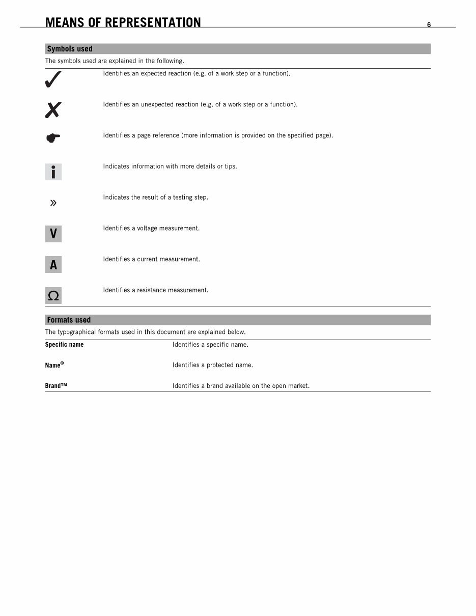
MEANS OF REPRESENTATION 6
~ balsus.d
The symbols used are explained in the following.
Identifies an expected reaction (e.g. of a work step or a function).
x
Identifies an unexpected reaction (e.g. of a work step or a function).
Identifies a page reference (more information is provided on the specified page).
•
I
Indicates information with more details or tips .
»
Indicates the result of a testing step.
v
Identifies a voltage measurement.
A
Identifies a current measurement.
Identifies a resistance measurement.
Fannaa used
The typographical formals used in this document are explained below.
Specific name Identifies a specific name.
Identifies a protected name.
Identifies a brand available on the open market.
MEANS OF REPRESENTATION 6
~ balsus.d
The symbols used are explained in the following.
Identifies an expected reaction (e.g. of a work step or a function).
x
Identifies an unexpected reaction (e.g. of a work step or a function).
Identifies a page reference (more information is provided on the specified page).
•
I
Indicates information with more details or tips .
»
Indicates the result of a testing step.
v
Identifies a voltage measurement.
A
Identifies a current measurement.
Identifies a resistance measurement.
Fannaa used
The typographical formals used in this document are explained below.
Specific name Identifies a specific name.
Identifies a protected name.
Identifies a brand available on the open market.
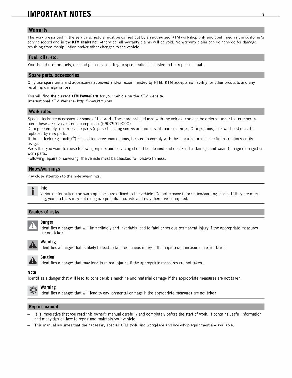
IMPORTANT NOTES 7
WalTl!!IJ
The work prescribed in the service schedule must be carried out by an authorized KTM workshop only and confirmed in the customer's
service record and in the KTM deller.net; otherwise, all warranty claims will be void. No warranty claim can be honored for damage
resulting from manipulation and/or other changes to the vehicle.
FUll, 0111, etc.
You should use the fuels, oils and greases according to specifications as listed in the repair manual.
SJI!!re Jl!!rtI accessories
Only use spare parts and accessories approved and/or recommended by KTM. KTM accepts no liability for other products and any
resulting damage or loss.
You will find the current KIM PDwerPiris for your vehicle on the KTM website.
International KTM Website, httpdlwww.ktm.com
Work rules
Special tools are necessary for some of the work. These are not included with the vehicle and can be ordered under the number in
parentheses. Ex, valve spring compressor (59029019000)
During assembly, non·reusable parts (e.g. self·locking screws and nuts, seals and seal rings, O'rings, pins, lock washers) must be
replaced by new parts.
If thread lock (e.g. Loctite
e
) is used for screw connections, be sure to comply with the manufacturer's specific instructions on its
usage.
Parts that you want to reuse following repairs and servicing should be cleaned and checked for damage and wear. Change damaged or
worn parts.
Following repairs or servicing, the vehicle must be checked for roadworthiness.
NDtIIIwaml!IP
Pay close attention to the noteslwarnings.
• Info
I Various information and warning labels are affixed to the vehicle. Do not remove informationlWarning labels. If they are miss-
ing, you or others may not recognize potential hazards and may therefore be injured.
Grades 01 risks
n Danger
W Identifies a danger that will immediately and invariably lead to fatal or serious permanent injury if the appropriate measures
are not taken.
Warning
Identifies a danger that is likely to lead to fatal or serious injury if the appropriate measures are not taken.
Caution
Identifies a danger that may lead to minor injuries if the appropriate measures are not taken.
Note
Identifies a danger that will lead to considerable machine and material damage if the appropriate measures are not taken.
* Warning
'f1" Identifies a danger that will lead to environmental damage if the appropriate measures are not taken.
RIJI!!lr manual
- It is imperative that you read this owner's manual carefully and completely before the start of work. It contains useful information
and many tips on how to repair and maintain your vehicle.
- This manual assumes that the necessary special KTM tools and workplace and workshop equipment are available.
IMPORTANT NOTES 7
WalTl!!IJ
The work prescribed in the service schedule must be carried out by an authorized KTM workshop only and confirmed in the customer's
service record and in the KTM deller.net; otherwise, all warranty claims will be void. No warranty claim can be honored for damage
resulting from manipulation and/or other changes to the vehicle.
FUll, 0111, etc.
You should use the fuels, oils and greases according to specifications as listed in the repair manual.
SJI!!re Jl!!rtI accessories
Only use spare parts and accessories approved and/or recommended by KTM. KTM accepts no liability for other products and any
resulting damage or loss.
You will find the current KIM PDwerPiris for your vehicle on the KTM website.
International KTM Website, httpdlwww.ktm.com
Work rules
Special tools are necessary for some of the work. These are not included with the vehicle and can be ordered under the number in
parentheses. Ex, valve spring compressor (59029019000)
During assembly, non·reusable parts (e.g. self·locking screws and nuts, seals and seal rings, O'rings, pins, lock washers) must be
replaced by new parts.
If thread lock (e.g. Loctite
e
) is used for screw connections, be sure to comply with the manufacturer's specific instructions on its
usage.
Parts that you want to reuse following repairs and servicing should be cleaned and checked for damage and wear. Change damaged or
worn parts.
Following repairs or servicing, the vehicle must be checked for roadworthiness.
NDtIIIwaml!IP
Pay close attention to the noteslwarnings.
• Info
I Various information and warning labels are affixed to the vehicle. Do not remove informationlWarning labels. If they are miss-
ing, you or others may not recognize potential hazards and may therefore be injured.
Grades 01 risks
n Danger
W Identifies a danger that will immediately and invariably lead to fatal or serious permanent injury if the appropriate measures
are not taken.
Warning
Identifies a danger that is likely to lead to fatal or serious injury if the appropriate measures are not taken.
Caution
Identifies a danger that may lead to minor injuries if the appropriate measures are not taken.
Note
Identifies a danger that will lead to considerable machine and material damage if the appropriate measures are not taken.
* Warning
'f1" Identifies a danger that will lead to environmental damage if the appropriate measures are not taken.
RIJI!!lr manual
- It is imperative that you read this owner's manual carefully and completely before the start of work. It contains useful information
and many tips on how to repair and maintain your vehicle.
- This manual assumes that the necessary special KTM tools and workplace and workshop equipment are available.
SERIAL NUMBERS B
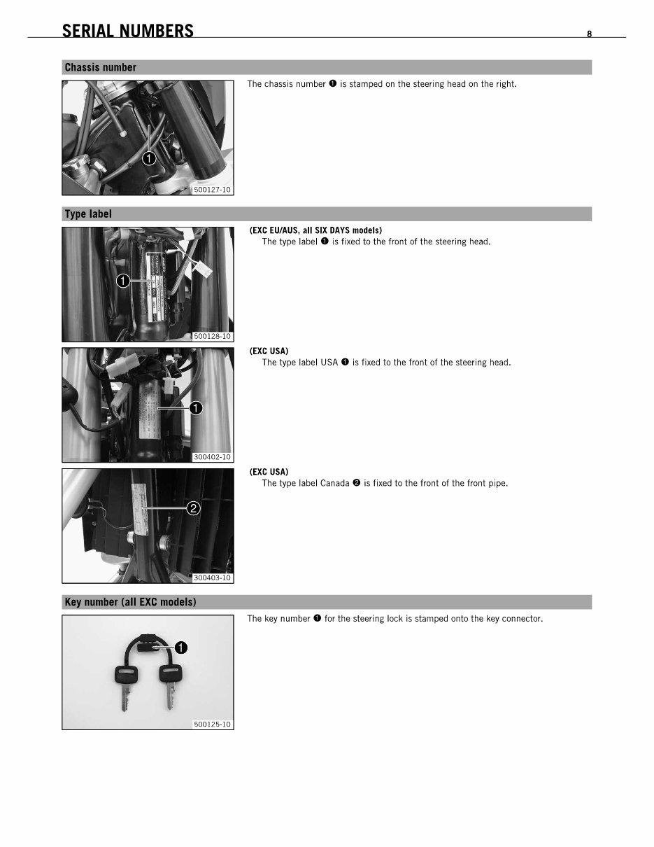
The chassis number. is stamped on the steering head on the right.
(EXC ElIfAUS, all SIX DAYS models)
The type label 0 is fixed to the front of the steering head.
(EXC USA)
The type label USA. is fixed to the front of the steering head.
(EXC USA)
The type label Canada. is fixed to the front of the front pipe.
K~ number (all EXC madllS)
The key number. for the steering lock is stamped onto the key connector.
50012!>-10
SERIAL NUMBERS B
The chassis number. is stamped on the steering head on the right.
(EXC ElIfAUS, all SIX DAYS models)
The type label 0 is fixed to the front of the steering head.
(EXC USA)
The type label USA. is fixed to the front of the steering head.
(EXC USA)
The type label Canada. is fixed to the front of the front pipe.
K~ number (all EXC madllS)
The key number. for the steering lock is stamped onto the key connector.
50012!>-10
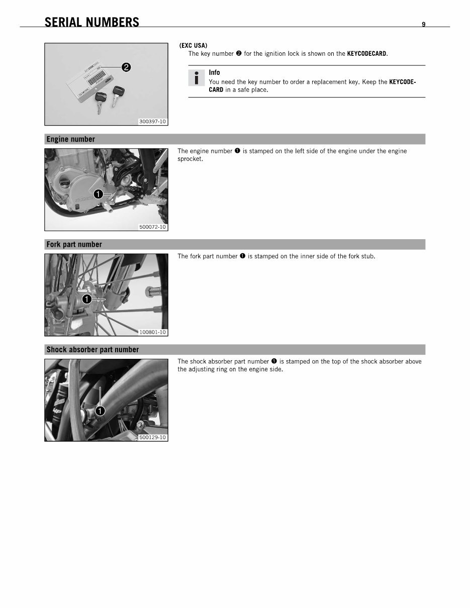
SERIAL NUMBERS
300397-10
(EXC USA)
The key number. for the ignition lock is shown on the KEYCODECARD.
• Info
I You need the key number to order a replacement key. Keep the KEYCODE-
CARD in a safe place.
The engine number. is stamped on the left side of the engine under the engine
sprocket.
The fork part number. is stamped on the inner side of the fork stub.
The shock absorber part number 0 is stamped on the top of the shock absorber above
the adjusting ring on the engine side.
9 SERIAL NUMBERS
300397-10
(EXC USA)
The key number. for the ignition lock is shown on the KEYCODECARD.
• Info
I You need the key number to order a replacement key. Keep the KEYCODE-
CARD in a safe place.
The engine number. is stamped on the left side of the engine under the engine
sprocket.
The fork part number. is stamped on the inner side of the fork stub.
The shock absorber part number 0 is stamped on the top of the shock absorber above
the adjusting ring on the engine side.
9
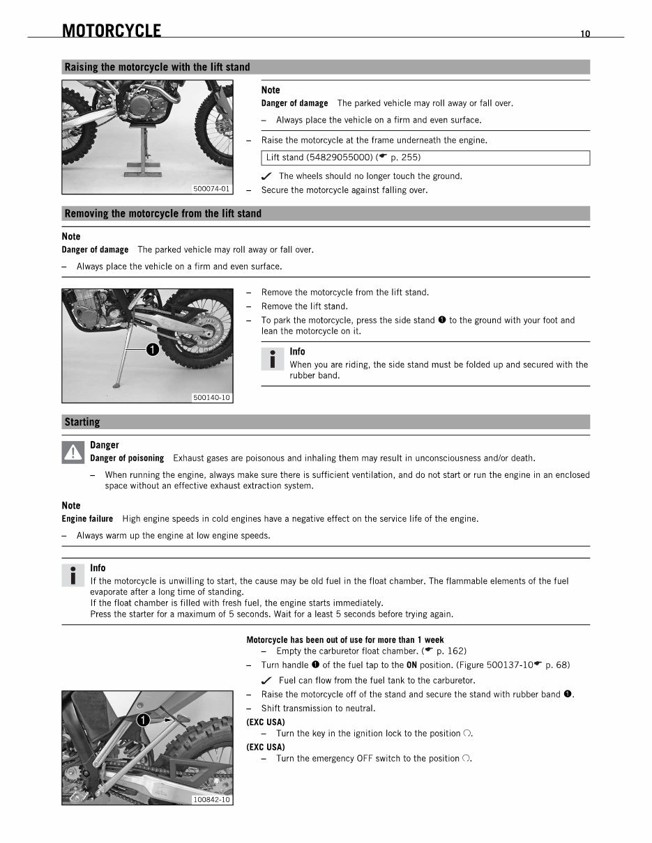
MOTORCYCLE
Note
Danger 01 damage The parked vehicle may roll away or fall over.
- Always place the vehicle on a firm and even surface.
- Raise the motorcycle at the frame underneath the engine.
I Lift stand (54829055000) ( .. p. 255)
,/ The wheels should no longer touch the ground.
- Secure the motorcycle against falling over.
RlmDYinllll1 mDta ~11 from 1111 lift stand
Note
Danger 01 damage The parked vehicle may roll away or fall over.
- Always place the vehicle on a firm and even surface.
- Remove the motorcycle from the lift stand.
- Remove the lift stand.
- To park the motorcycle, press the side stand. to the ground with your foot and
lean the motorcycle on it.
• Info
10
I When you are riding, the side stand must be folded up and secured with the
rubber band.
~ Danpr
W Danger of poisoning Exhaust gases are poisonous and inhaling them may result in unconsciousness andlor death.
Note
- When running the engine, always make sure there is sufficient ventilation, and do not start or run the engine in an enclosed
space without an effective exhaust extraction system.
Engine failure High engine speeds in cold engines have a negative effect on the service life of the engine.
- Always warm up the engine at low engine speeds.
• Info
I If the motorcycle is unwilling to start, the cause may be old fuel in the float chamber. The flammable elements of the fuel
evaporate after a long time of standing.
If the float chamber is filled with fresh fuel, the engine starts immediately.
Press the starter for a maximum of 5 seconds. Wait for a least 5 seconds before trying again.
Motorcycle has been out of use lor more than 1 week
- Empty the carburetor float chamber. ( .. p. 162)
- Turn handle. of the fuel tap to the ON position. (Figure 500137-10" p. 68)
,/ Fuel can flow from the fuel tank to the carburetor.
- Raise the motorcycle off of the stand and secure the stand with rubber band •.
- Shift transmission to neutral.
(EXC USA)
- Turn the key in the ignition lock to the position O.
(EXC USA)
- Turn the emergency OFF switch to the position O.
MOTORCYCLE
Note
Danger 01 damage The parked vehicle may roll away or fall over.
- Always place the vehicle on a firm and even surface.
- Raise the motorcycle at the frame underneath the engine.
I Lift stand (54829055000) ( .. p. 255)
,/ The wheels should no longer touch the ground.
- Secure the motorcycle against falling over.
RlmDYinllll1 mDta ~11 from 1111 lift stand
Note
Danger 01 damage The parked vehicle may roll away or fall over.
- Always place the vehicle on a firm and even surface.
- Remove the motorcycle from the lift stand.
- Remove the lift stand.
- To park the motorcycle, press the side stand. to the ground with your foot and
lean the motorcycle on it.
• Info
10
I When you are riding, the side stand must be folded up and secured with the
rubber band.
~ Danpr
W Danger of poisoning Exhaust gases are poisonous and inhaling them may result in unconsciousness andlor death.
Note
- When running the engine, always make sure there is sufficient ventilation, and do not start or run the engine in an enclosed
space without an effective exhaust extraction system.
Engine failure High engine speeds in cold engines have a negative effect on the service life of the engine.
- Always warm up the engine at low engine speeds.
• Info
I If the motorcycle is unwilling to start, the cause may be old fuel in the float chamber. The flammable elements of the fuel
evaporate after a long time of standing.
If the float chamber is filled with fresh fuel, the engine starts immediately.
Press the starter for a maximum of 5 seconds. Wait for a least 5 seconds before trying again.
Motorcycle has been out of use lor more than 1 week
- Empty the carburetor float chamber. ( .. p. 162)
- Turn handle. of the fuel tap to the ON position. (Figure 500137-10" p. 68)
,/ Fuel can flow from the fuel tank to the carburetor.
- Raise the motorcycle off of the stand and secure the stand with rubber band •.
- Shift transmission to neutral.
(EXC USA)
- Turn the key in the ignition lock to the position O.
(EXC USA)
- Turn the emergency OFF switch to the position O.
You're Reading a Preview
What's Included?
 Lifetime Access
Fast Download Speeds
Online & Offline Access
Access PDF Contents & Bookmarks
Full Search Facility
Print one or all pages of your manual
$28.99
2008 KTM 450 EXC-R, 450 EXC-R SIX DAYS, 450 EX SIX DAYSC-R, 450 XCR-W, 530 EXC-R, 530 XCR-W Motorcycle also Covers Engine Servic
Viewed 49 Times Today

What's Included?
Lifetime Access
Fast Download Speeds
Online & Offline Access
Access PDF Contents & Bookmarks
Full Search Facility
Print one or all pages of your manual
$28.99

Secure transaction
What's Included?
Lifetime Access
Fast Download Speeds
Online & Offline Access
Access PDF Contents & Bookmarks
Full Search Facility
Print one or all pages of your manual
Description
This manual is suitable for both first-time owners and amateur enthusiasts, as well as professional technicians. It provides easy-to-read instructions and all the necessary information to perform procedures correctly. Regular reference to this service manual is recommended to ensure the proper execution of routine and preventive maintenance, ultimately saving time and money by preventing premature failure and unnecessary repairs.
- Models Covered:
- 2008 KTM 450 EXC-R EU
- 2008 KTM 450 EXC-R AUS/UK
- 2008 KTM 450 EXC-R SIX DAYS
- 2008 KTM 450 EXC-R USA
- 2008 KTM 450 XCR-W USA
- 2008 KTM 450 XCR-W ZA
- 2008 KTM 530 EXC-R EU
- 2008 KTM 530 EXC-R AUS/UK
- 2008 KTM 530 EXC-R SIX DAYS
- 2008 KTM 530 EXC-R USA
- 2008 KTM 530 XCR-W USA
- 2008 KTM 530 XCR-W ZA
- Manual Contents:
- Fork, Triple Clamp
- Frame
- Shock Absorber, Swingarm
- Exhaust
- Air Filter
- Fuel Tank, Seat, Trim
- Mask, Fender
- Front Wheel
- Rear Wheel
- Wiring Harness, Battery
- Brake System
- Light System, Instruments
- Engine
- Disassembling The Engine
- Engine - Work On Individual Parts
- Assembling The Engine
- Carburetor
- Clutch
- Transmission
- Water Pump, Cooling System
- Lubrication System
- Ignition System
- Electric Starter
- Troubleshooting
- Technical Data - Engine
- Technical Data - Tolerance, Wear Limits Of Engine
- Technical Data - Engine Tightening Torques
- Technical Data - Carburetor
- Technical Data - Carburetor Tightening Torques
- Technical Data - Chassis
- Technical Data - Fork
- Technical Data - Shock Absorber
- Technical Data - Chassis Tightening Torques
- Cleaning
- Storage
- Greasing And Service Table
- Wiring Diagram
- Substances
- Auxiliary Substances
- Special Tools
- Standards
File Format: PDF
Compatibility: All Versions of Windows & Mac
Language: English
Requirements: Adobe Reader


