

KTM 200 Owners Manual
What's Included?
Fast Download Speeds
Offline Viewing
Access Contents & Bookmarks
Full Search Facility
Print one or all pages of your manual
Art.Nr. 3.210.49 04/2002
125/200/250/300 SX, MXC, EXC
OWNERS HANDBOOK
MANUALE D’USO
MANUEL D’UTILISATION
MANUAL DE INSTRUCCIONES
2003
BEDIENUNGSANLEITUNG
ENGLISH
1
IMPORTANT
PLEASE READ THIS MANUAL CAREFULLY AND COMPLETELY
BEFORE GOING ON YOUR FIRST RIDE. IT CONTAINS A GREAT
DEAL OF INFORMATION AND ADVICE WHICH WILL HELP YOU
USE AND HANDLE YOUR BIKE PROPERLY. IN YOUR OWN INTE-
REST, PLEASE PAY PARTICULAR ATTENTION TO NOTICES THAT
ARE MARKED AS FOLLOWS:
WARNING
IGNORING THESE INSTRUCTIONS, CAN BE DANGEROUS TO
LIFE AND LIMB.
! CAUTION !
IGNORING THESE INSTRUCTIONS MAY DAMAGE PARTS OF THE
MOTORCYCLE OR IMPAIR THE MOTORCYCLE’S TRAFFIC
SAFETY.
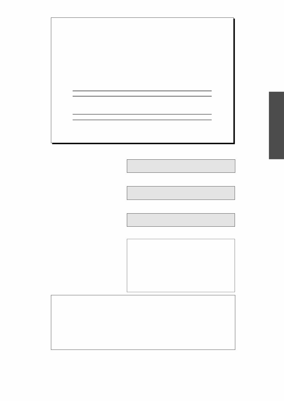
Please insert the serial numbers of your motorcycle in the boxes below
Chassis number
Engine number
Key number
Stamp of dealer
Tampering with noise control system prohibited
Owners are warned that the law may prohibit:
(a) The removal or rendering inoperative by any person other than for purposes of mainte-
nance, repair or replacement, of any device or element of design incorporated into any new
vehicle for the purpose of noise control prior to its sale or delivery to the ultimate purchaser
or while it is in use; and
(b) the use of the vehicle after such device or element of design has been removed or rendered
inoperative by any person.
COMSUMER INFORMATION FOR AUSTRALIA ONLY
KTM SPORTMOTORCYCLE AG RESERVES THE RIGHT TO MODIFY ANY EQUIPMENT, TECHNICAL SPECIFICATIONS, COLORS,
MATERIALS, SERVICES OFFERED AND RENDERED, AND THE LIKE SO AS TO ADAPT THEM TO LOCAL CONDITIONS WITHOUT
PREVIOUS ANNOUNCEMENT AND WITHOUT GIVING REASONS, OR TO CANCEL ANY OF THE ABOVE ITEMS WITHOUT
SUBSTITUTING THEM WITH OTHERS. IT SHALL BE ACCEPTABLE TO STOP MANUFACTURING A CERTAIN MODEL WITHOUT
PRIOR NOTICE . IN THE EVENT OF SUCH MODIFICATIONS, PLEASE ASK YOUR LOCAL KTM DEALER FOR INFORMATION.

ENGLISH
2
Introduction
We would like to congratulate you on your purchase of a KTM motorcycle.
You are now the owner of a state-of-the-art sports motorcycle that guarantees to bring
you lots of fun and enjoyment, provided that you clean and maintain it appropriately.
Before you go for your first ride, be sure to read this manual carefully and thoroughly in
order to familiarize yourself with how to operate your new motorcycle and with its cha-
racteristics, even if this means that you will have to dedicate some of your valuable
time to this task. Only by doing so will you learn how to tune your motorbike to your
specific needs and how to protect yourself against injury. Besides, this manual contains
important information on motorcycle maintenance. At the time this manual was typeset,
it was up-to-date with the latest state of this production series. It cannot be completely
ruled out, however, that minor discrepancies may exist resulting from further design upg-
rades of these motorcycles.This manual is an important part of your motorbike and
should be passed on to any subsequent owner in case you decide to sell it.
We expressly point out that work marked with an asterisk in the chapter "Maintenance
work on the chassis and engine" must be performed by a KTM workshop. If mainten-
ance work should become necessary during a competition, it must be performed by a
trained mechanic.
For your own safety, use KTM-approved parts and accessories only. KTM is not liable
for damage that arises in connection with the use of other products.
Take special care to follow the recommended run in, inspection, and maintenance inter-
vals. Heeding these guidelines will significantly increase the life of your motorcycle. Have
services carried out by a KTM dealer so that your warranty claim remains intact.
Off-road motorcycle driving is a wonderful sport and we hope that you will be able to
enjoy it to the full. It may, however, involve potential problems for the environment or
lead to conflicts with others. These problems or conflicts can be avoided if the motorcycle
is used responsibly. To safeguard the future of motorcycle sports, make sure that you use
the motorcycle in accordance with the law, show that you are environmentally conscious
and respect the rights of others.
We wish you a lot of fun when driving !
KTM SPORTMOTORCYCLE AG
5230 MATTIGHOFEN, AUSTRIA
Attachments: Spare parts manual chassis & engine
ALL RIGHTS RESERVED TO MAKE ALTERATIONS TO DESIGN AND MODEL.
© by KTM SPORTMOTORCYCLE AG, AUSTRIA All rights reserved

ENGLISH
3
IMPORTANT WARRANTY AND
GUARANTEE INFORMATION
KTM sports motorcycles are designed and constructed to resist the usual
wear and tear of normal use in competitions.
The motorcycles comply with the regulations and categories currently in
effect with the leading international motorcycle associations.
Observance of the service, maintenance and tuning instructions for the
engine and chassis specified in the Owner's Manual is a prerequisite for
faultless operation and the avoidance of premature wear. An improperly
tuned chassis can lead to damage and breakage of the chassis components
(see chapter on checking the basic chassis setting).
The service work specified in the "Lubrication and Maintenance Schedule"
must be performed by a KTM workshop and recorded in the service manual
otherwise claims under the warranty shall become void.
The fuels and lubricants specified in the Owner's Manual or automotive
fluids with equivalent specifications must be used in accordance with the
maintenance schedule.
No claims can be filed under the warranty for damage or consequential
damage caused by manipulations or conversions to the motorcycle.
The use of the motorcycle under extreme conditions, e.g. on extremely
muddy and wet terrain, can lead to higher than average wear on
components such as the drive train or the brakes. In this case it may become
necessary to service or replace wear parts before the service limit specified in
the maintenance schedule has been reached.
THE SX/SXS AND MXC MODELS ARE PROHIBITED ON PUBLIC ROADS.
The EXC models are only allowed on public roads in the original
homologated (throttled) version. Without this performance restriction (i.e.
dethrottled), these models are only allowed to be driven off-road but not on
public roads. The EXC models are designed for off-road sports endurance
competitions(enduro) and not suitable for predominant motocross use.
In accordance with the international quality management
ISO 9001 standard, KTM uses quality assurance processes
that lead to the highest possible product quality.

ENGLISH
4
Page
SERIAL NUMBER LOCATIONS .............................................5
Chassis number ................................................................5
Engine number, engine type (125/200)............................5
Engine number, engine type (250/300)............................5
OPERATION INSTRUMENTS ...............................................5
Clutch lever .....................................................................5
Hand brake lever ..............................................................5
Electronic speedometer, indicator lamp (EXC)...................6
Electronic speedometer ....................................................6
Tripmaster switch .............................................................7
Short circuit button (SX) .................................................11
Combination switch (EXC)..............................................11
Headlamp switch (EXC USA) ..........................................11
Flasher switch.................................................................11
Emergency OFF switch (Australia) ..................................11
Filler cap.........................................................................12
Fuel tap ..........................................................................12
Choke knob ...................................................................12
Shift lever .......................................................................12
Kickstarter ......................................................................13
Foot brake pedal ............................................................13
Side stand ......................................................................13
Steering lock ..................................................................13
Compression damping of fork ........................................14
Rebound damping of fork ..............................................14
Compression damping of shock absorber (SX) ................14
Compression damping of shock absorber (MXC, EXC) ...15
Rebound damping of shock absorber (SX, MXC, EXC) ...15
GENERAL TIPS AND WARNINGS FOR STARTING THE
MOTORCYCLE...................................................................16
Instructions for your first ride .........................................16
Running in .....................................................................16
DRIVING INSTRUCTIONS ..................................................17
What you should check before each start .......................17
Starting when the engine is cold.....................................18
Starting when the engine is warm ..................................18
What to do when the engine is “flooded“ .....................18
Starting off .....................................................................18
Shifting, Riding...............................................................18
Braking...........................................................................19
Stopping, Parking ...........................................................19
Refueling, fuel ................................................................19
PERIODIC LUBRICATION - AND MAINTENANCE-SCHEDULE ....20
MAINTENANCE WORK ON CHASSIS AND ENGINE ..........24
Checking and adjusting the steering head bearing..........24
How to change the handlebar position ...........................25
Breather plug front fork..................................................25
Cleaning the dust sleeves of the telescopic fork ..............25
Basic suspension setup for the weight of the driver ........26
Checking the shock absorber and spring ........................26
Determining the static sag of the shock absorber ...........26
Determining the riding sag of the shock absorber...........26
Checking the basic setup of the telescopic fork ..............27
Changing the spring preload on the telescopic fork (SX models) 27
Page
Changing the spring preload on the telescopic fork (MXC/EXC models).27
Replacing fork springs ....................................................27
Adjusting the spring preload on the fork (SX) .................28
Changing the spring preloading of the shock absorber ...28
Pivot bearing ..................................................................28
Checking the chain tension ............................................29
Correct the chain tension ...............................................29
Chain maintenance ........................................................30
Chain wear.....................................................................30
General information about KTM disc brakes ...................31
Adjusting the free travel at the hand brake lever ............32
Checking the brake fluid level - front brake ....................32
Refilling the front brake fluid reservoir............................32
Checking the front brake pads .......................................32
Replacing the front brake pads .......................................33
Changing the basic position of the foot brake pedal .......33
Checking the rear brake fluid level .................................33
Refilling the rear brake fluid reservoir .............................33
Checking the rear brake pads .........................................34
Replacing the rear brake pads ........................................34
Dismounting and mounting the front wheel ...................34
Dismounting and mounting the rear wheel ....................35
Tires, air pressure ...........................................................36
Checking the spoke tension............................................36
Replacing the battery of the electronic speedometer ......36
Setting the clock of the electronic speedometer..............37
Checking/setting the distance of the magnetic sensor ....38
Replacing the headlight lamp .........................................38
Cooling system...............................................................39
Radiator cover for the cold season..................................39
Checking the coolant level .............................................39
Refilling / Bleeding the cooling system ...........................40
Cleaning the air filter ......................................................40
Changing the original position of the clutch lever ..............41
Checking the oil level of the hydraulic clutch ..................41
Bleeding of the hydraulic clutch......................................41
Exhaust system...............................................................41
Cleaning the spark arrestor (EXC USA) ...........................42
Carburetor adjustment ...................................................42
Draining the float chamber of the carburetor .................43
Checking the float level ..................................................43
Checking the transmission oil level (125/200) ................44
Changing the transmission oil (125/200)........................44
Checking the transmission oil level (250/300) ................44
Changing the transmission oil (250/300)........................44
CLEANING..........................................................................45
CONSERVATION FOR WINTER OPERATION ....................45
STORAGE ...........................................................................45
Using RE Iniation ............................................................45
TECHNICAL SPECIFICATIONS - CHASSIS (125/200)..........46
TECHNICAL SPECIFICATIONS - ENGINE (125/200) ...........48
TECHNICAL SPECIFICATIONS - CHASSIS (250/300) ............50
TECHNICAL SPECIFICATIONS - ENGINE (250/300) ...........52
INDEX.................................................................................54
WIRING DIAGRAM, CARBURETOR SETTING............Appendix
TABLE OF CONTENTS
ENGLISH
5
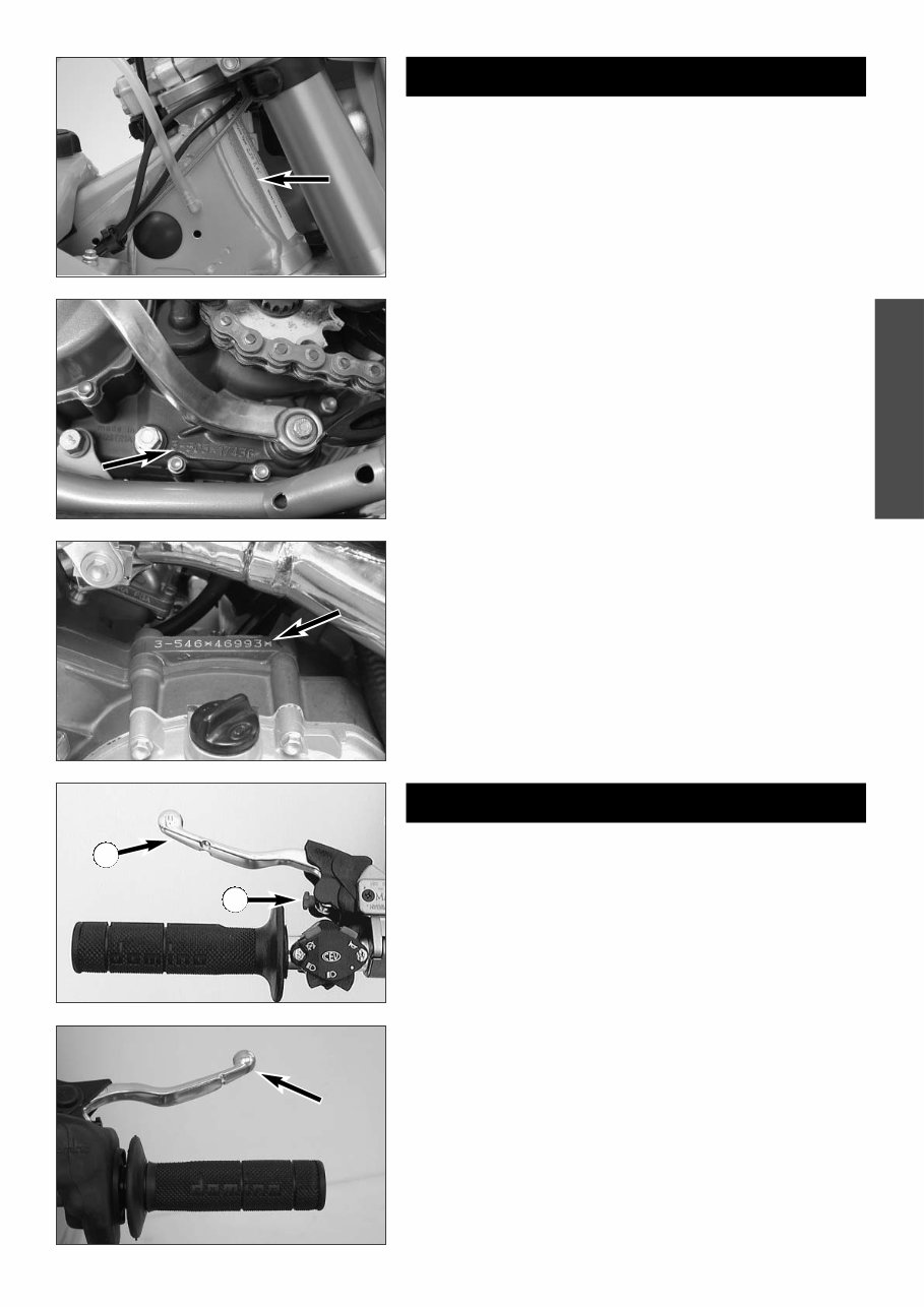
Chassis number
The chassis number is stamped on the right side of the steering head tube.
Enter this number in the field on page no 1.
Engine number, engine type (125/200)
The engine number and the engine type are stamped into the left side of
the engine below the engine sprocket. Enter this number on page 1.
Engine number, engine type (250/300)
Engine number and engine type are stamped on the right hand side of the
engine in front of the kickstarter. Enter this number in the relevant field on
page 1.
SERIAL NUMBER LOCATIONS
OPERATION INSTRUMENTS
Clutch lever
The clutch lever 1 is located on the left side of the handlebars. The adjust-
ing screw A is used to change the original position of the clutch lever (see
maintenance work on chassis and engine).
Hand brake lever
The hand brake lever is mounted on the handlebars on the right and actu-
ates the front wheel brake.
1
A
ENGLISH
6
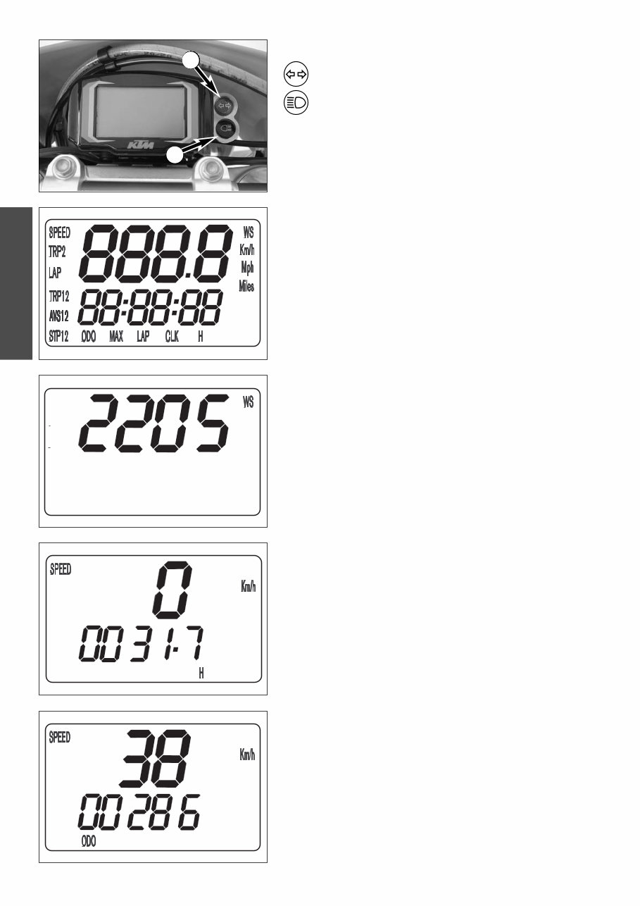
Electronic speedometer, indicator lamp (EXC)
The green control lamp 1 flashes in the same rhythm as the
flashing indicator when the indicator is working.
The blue control lamp 2 lights up when the high beam is on.
Electronic speedometer
The electronic speedometer display is activated as soon as the engine is
switched on and the motorcycle starts to move.
The engine must be started in order for the speedometer to be supplied
with electricity from the generator. An impulse must be received from the
wheel sensor to activate the display; the front wheel must turn at least one
time.
TEST
All of the display elements will light up for 1 second for the function test.
WS (wheel size)
The display will change and briefly show the diameter of the front wheel in
millimeters.
If the front wheel does not turn, the display will automatically change to the
SPEED/H mode.
If the front wheel turns, the display will automatically change to the
SPEED /ODO mode.
SPEED/H (hours) display mode
When you stop driving and no impulses are sent from the wheel sensor, the
display mode will automatically change from SPEED/ODO to SPEED/H. H
shows the operating hours. The operating hour counter starts to count as
soon as you start the engine. The displayed figure cannot be cleared.
Service intervals are indicated in operating hours for some KTM offroad
motorcycles, making the operating hour counter a very practical function.
Anzeigemodus SPEED/ODO
The SPEED/ODO mode shows the speed and the total kilometers traveled.
When the front wheel stops turning, the display will automatically change
to the SPEED/H mode.
The information will disappear in the display when the front wheel stops
turning for 1 minute.
NOTE:
A Tripmaster switch is available as an accessory and enhances the electronic
speedometer by providing the following functions:
2x Tripmaster
2x chronometer for the lap time
Average speed
Maximum speed
Clock
Display in miles
1
2
ENGLISH
7
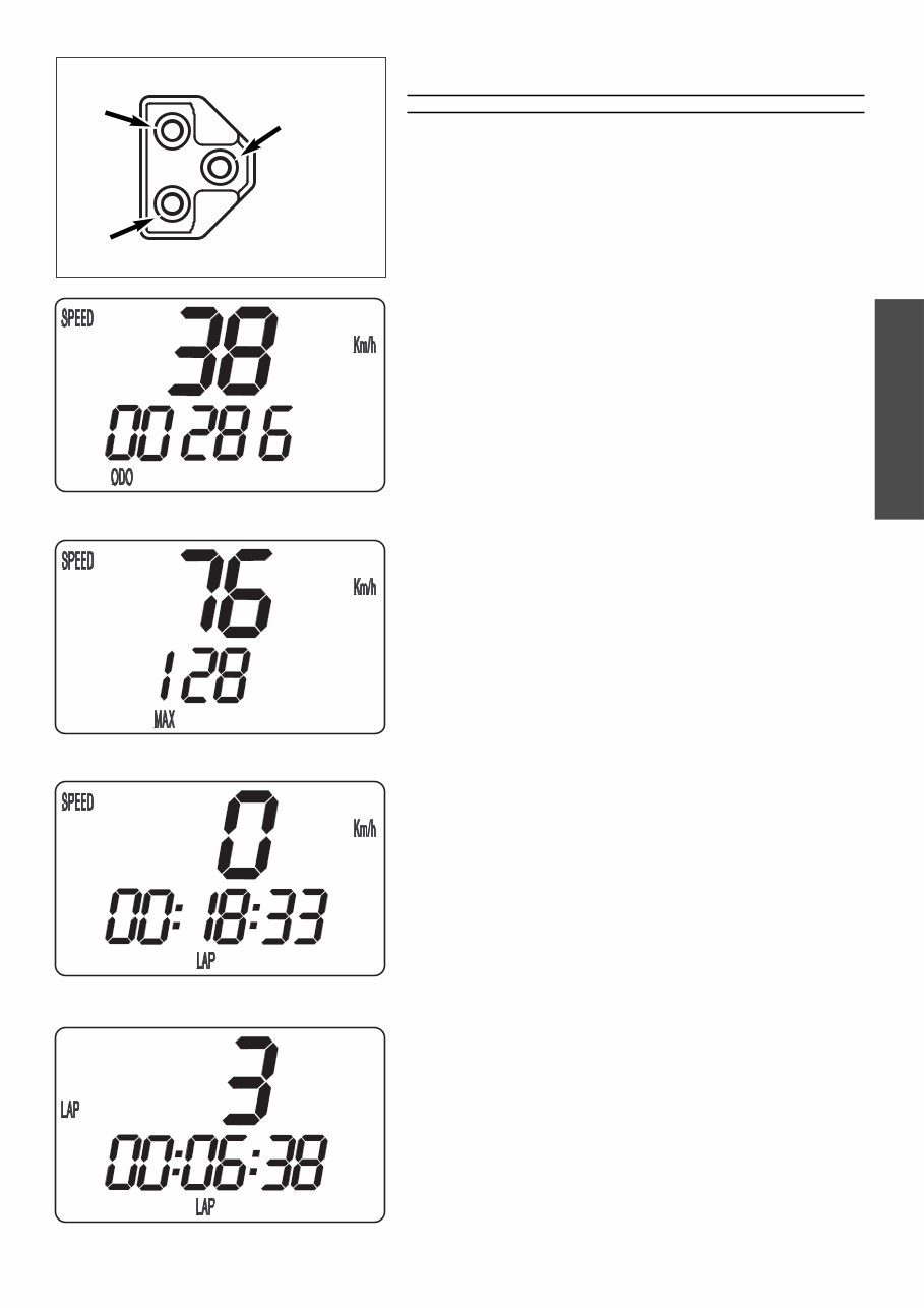
+
–
MODE
Tripmaster switch
The switch has three buttons: MODE, + (plus) and – (minus).
WARNING
DO NOT TRY TO CHANGE THE MODE OR READ THE SETTINGS WHILE DRIVING. YOUR
ATTENTION WILL BE DISTRACTED FROM THE TRAFFIC WHICH CAN EASILY LEAD TO AN
ACCIDENT.
Electronic speedometer functions provided by the Tripmaster
switch
The display modes on the electronic speedometer will change in the follo-
wing order. If not, please read the chapter "ACTIVATING AND DEACTIVA-
TING THE DISPLAY MODE."
SPEED/ODO display mode
SPEED displays the speed in KPH or MPH. The displayed figure cannot be
cleared.
ODO displays the kilometers or miles traveled. The displayed figure cannot
be cleared.
+ BUTTON no function
– BUTTON no function
press the MODE BUTTON to change to the next mode
press and hold the MODE BUTTON 3 SECONDS to change to the next mode
SPEED/MAX display mode
MAX displays the maximum speed. It is always active.
+ BUTTON no function
– BUTTON no function
press the MODE BUTTON to change to the next mode
press and hold the MODE BUTTON 3 SECONDS to reset the MAX figure to 0
SPEED/LAP display mode
LAP displays the stopped lap time in hours, minutes and seconds.
+ BUTTON Starts and stops the stop watch. The lap time is not reset to 0.
– BUTTON Stops the running stop watch, stores the lap time and restarts
the stop watch. The time is reset to 0. A total of 10 lap times
can be stored and read in the SPEED/LAP display mode. To
clear all of the stored lap times, hold the MODE button for 3
seconds in the SPEED/LAP mode.
press the MODE BUTTON to change to the next mode
If no lap time is stored or the motorcycle is driving, the LAP/LAP
mode will be skipped.
press and hold the MODE BUTTON 3 SECONDS to reset the LAP figure and all
stored lap times to 0
LAP/LAP display mode
The lap number is shown at the top and the lap time in hours, minutes and
seconds at the bottom of the display.
If no lap time is stored or the motorcycle is driving, the LAP/LAP mode will
be skipped.
Hold the MODE button for 3 seconds in the SPEED/LAP mode to clear the
stored lap times.
+ BUTTON changes to the next lap time.
– BUTTON no function
press the MODE BUTTON to change to the next mode
press and hold the MODE BUTTON 3 SECONDS to change to the next mode
ENGLISH
8
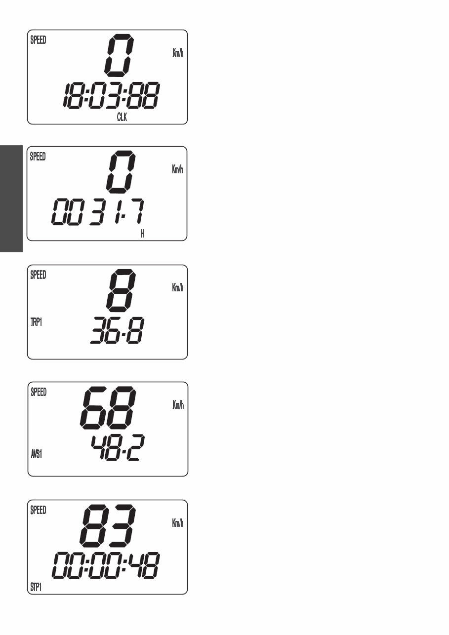
SPEED/CLK (clock) display mode
CLK will display time in hours, minutes and seconds.
+ BUTTON no function
– BUTTON no function
press the MODE BUTTON to change to the next mode.
press and hold the MODE BUTTON 3 SECONDS to set the time in the menu
(see SETTING THE CLOCK)
SPEED/H (hours) display mode
When you stop driving and no impulses are sent from the wheel sensor, the
display mode will automatically change from SPEED/ODO to SPEED/H. H
shows the operating hours. The operating hour counter starts to count as
soon as you start the engine. The displayed figure cannot be cleared.
Service intervals are indicated in operating hours for some KTM offroad
motorcycles, making the operating hour counter a very practical function.
+ BUTTON no function
– BUTTON no function
press the MODE BUTTON to change to the next mode
press and hold the MODE BUTTON 3 SECONDS to change to the SETUP mode
(see REVEALING/CONCEALING functions).
SPEED/TRP1 (trip 1) display mode
The TRP1 trip meter is always active and counts to 999.9. It is used to mea-
sure the length of a trip or the distance between 2 refueling stops.
TRP1 is linked to AVS1 and STP1. The calculation of these figures is activa-
ted by the first impulse received from the wheel sensor (when the front
wheel starts to turn) and stops 3 seconds after the last impulse is received
(when the front wheel has stopped).
The TRP1, AVS1 and STP1 figures are automatically reset to 0 after passing
999.9.
+ BUTTON no function
– BUTTON no function
press the MODE BUTTON to change to the next mode.
press and hold the MODE BUTTON 3 SECONDS to automatically reset the
TRP1, AVS1 and STP1 figures to 0.
SPEED/AVS1 (average speed 1) display mode
AVS1 is always active and shows the average speed based on the TRP1 and
STP1 figures. The calculation of this figure is activated by the first impulse
received from the wheel sensor and stops 3 seconds after the last impulse is
received.
+ BUTTON no function
– BUTTON no function
press the MODE BUTTON to change to the next mode
press and hold the MODE BUTTON 3 SECONDS to reset the TRP1, AVS1 and
STP1 figures to 0.
SPEED/STP1 (stop 1) display mode
STP1 shows the traveling time based on TRP1 and continues to count whe-
never it receives impulses from the wheel sensor. The calculation of this
figure is activated by the first impulse received from the wheel sensor and
stops 3 seconds after the last impulse is received.
+ BUTTON no function
– BUTTON no function
press the MODE BUTTON to change to the next mode
press and hold the MODE BUTTON 3 SECONDS to reset the TRP1, AVS1 and
STP1 figures to 0.
ENGLISH
9
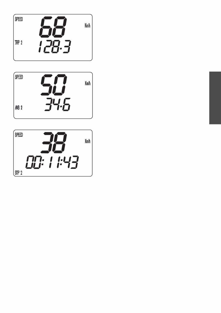
SPEED/TRP2 (trip 2) display mode
The TRP2 trip meter is always active and counts to 999.9. Contrary to
TRP1, the displayed figure can be changed using the + and – buttons. This
is a very useful function for trips taken according to a roadbook.
TRP2 is activated by the first impulse received from the wheel sensor and
stops automatically 3 seconds after the last impulse is received.
+ BUTTON increases the TRP2 figure
– BUTTON decreases the TRP2 figure
press the MODE BUTTON to change to the next mode
press and hold the MODE BUTTON 3 SECONDS to reset TRP2 to 0
SPEED/AVS2 (average speed 2) display mode
AVS2 shows the average speed based on the TRP2 and STP2 figures. The
calculation of this figure is activated by the first impulse received from the
wheel sensor and stops 3 seconds after the last impulse is received.
The displayed figure will deviate from the actual average speed if TRP2 was
changed manually or if STP2 was not stopped after the trip.
+ BUTTON no function
– BUTTON no function
press the MODE BUTTON to change to the next mode
press and hold the MODE BUTTON 3 SECONDS to change to the next mode
SPEED/STP2 (stop 2) display mode
STP2 is a manual stop watch. Start the stop watch by pressing the + but-
ton, press again to hold. Press again to continue timing.
Press the MODE button to change to the next mode. The STP2 display will
blink in the other modes if STP2 continues to run in the background. To
stop STP2, return to the SPEED/STP2 mode and press the + button.
+ BUTTON starts and stops the stop watch
– BUTTON no function
press the MODE BUTTON to change to the next mode
press and hold the MODE BUTTON 3 SECONDS to reset STP2 figures to 0
You're Reading a Preview
What's Included?
Fast Download Speeds
Offline Viewing
Access Contents & Bookmarks
Full Search Facility
Print one or all pages of your manual
$24.99
Viewed 62 Times Today


Secure transaction
What's Included?
Fast Download Speeds
Offline Viewing
Access Contents & Bookmarks
Full Search Facility
Print one or all pages of your manual
$24.99
This Benelli TNT Owners Manual contains important information for a safe use of the vehicle and to keep it in perfect working order.
As the Benelli TNT is a high performance vehicle that needs to be ridden with attention and skill.


