Table of Contents Uncrating ...................................................................................... 3 Opening Crate ............................................................................. 3 Parts Check ................................................................................. 4 Assembly ...................................................................................... 4 Steering Stem Head Nut ............................................................. 4 Clutch Cable ................................................................................ 5 Windshield ................................................................................... 5 Rider’s Seat Bolt .......................................................................... 5 Brake Disc Cleaning .................................................................... 5 Preparation ................................................................................... 6 Battery Service ............................................................................ 6 Front Brake Fluid ......................................................................... 13 Rear Brake Fluid ......................................................................... 15 Clutch Lever and Cable ............................................................... 17 Drive Chain.................................................................................. 17 Front Fork .................................................................................... 19 Rear Shock Absorber .................................................................. 20 Tire Air Pressures ........................................................................ 21 Fuel ............................................................................................. 21 Coolant ........................................................................................ 21 Engine Oil (4-stroke) ................................................................... 23 Throttle Grip and Cable ............................................................... 24 Rear Brake Light Switch .............................................................. 24 Idle Speed Adjustment ................................................................ 25 Headlight Aim .............................................................................. 25 Digital Meter ................................................................................ 25 Fastener Check ........................................................................... 28 Standard Torque Table ................................................................ 30 Test Ride the Motorcycle ............................................................. 30 A & P Check List ......................................................................... 30
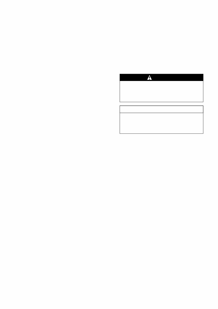
UNCRATING 3 Uncrating Opening Crate • Clear a space about 6 m (20 ft) square to give yourself plenty of space to work. • Place the crate upright on its base. • Remove the cardboard cover. • Remove the parts box. CAUTION When you remove the crate bracket from the motorcycle, be careful not to drop any parts and bracket onto the fuel tank and other components, and not to scratch the fuel tank by the crate bracket. This could damage the fuel tank or components. • First, remove the lower crate bolt (D = 22) at the steering stem and discard it. • Remove the upper crate bolts (D = 8) to take off the crate bracket and foam pad and dis- card them. A. Lower Crate Bolt (D = 22) B. Upper Crate Bolts (D = 8) C. Crate Bracket D. Foam Pad • Take out all the bolts and screws and remove the top and sides of the crate. • Lift the vehicle upward about 10 cm (4 in.) and remove the two lower support brackets. Roll the vehicle off the crate base. A. Lower Support Bracket
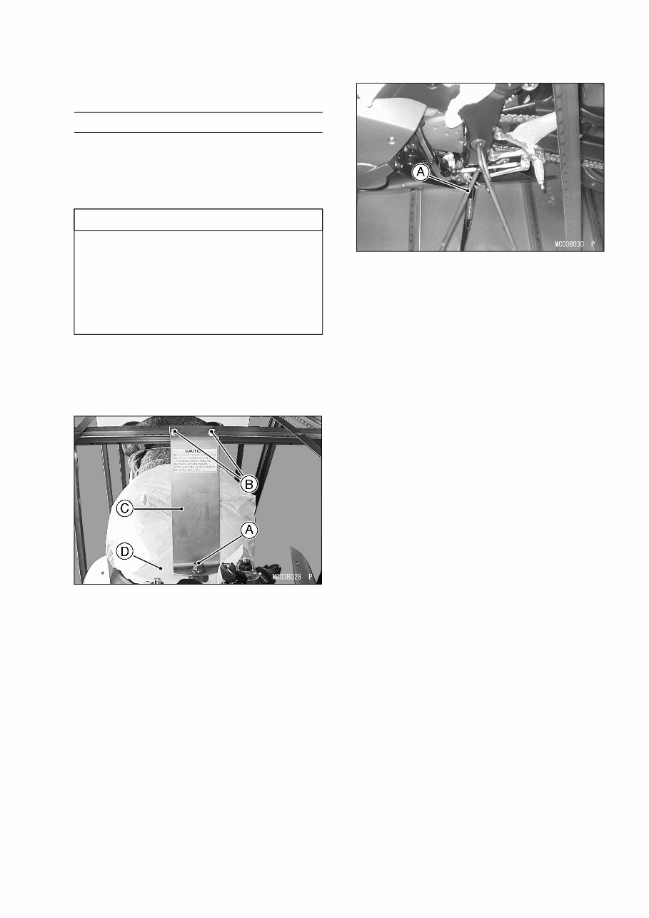
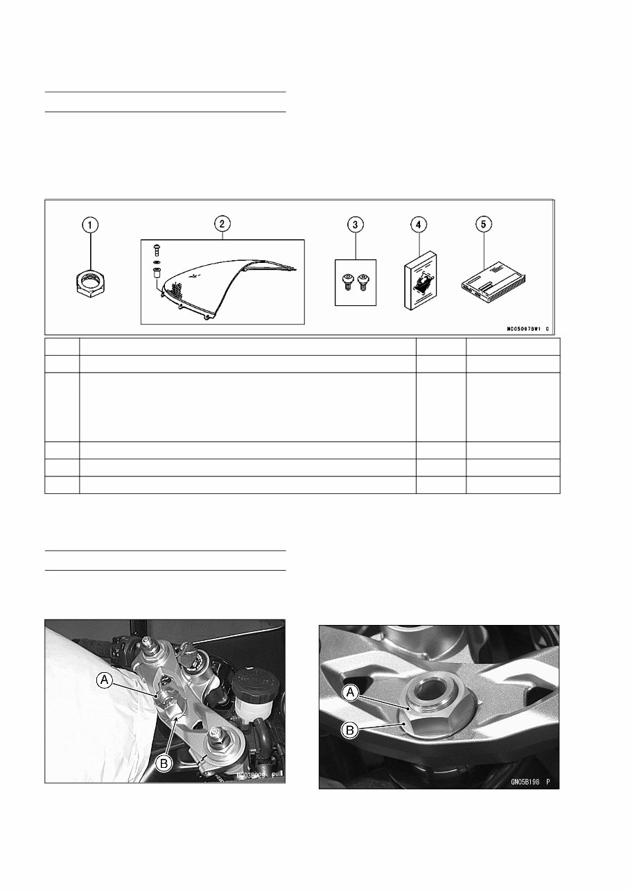
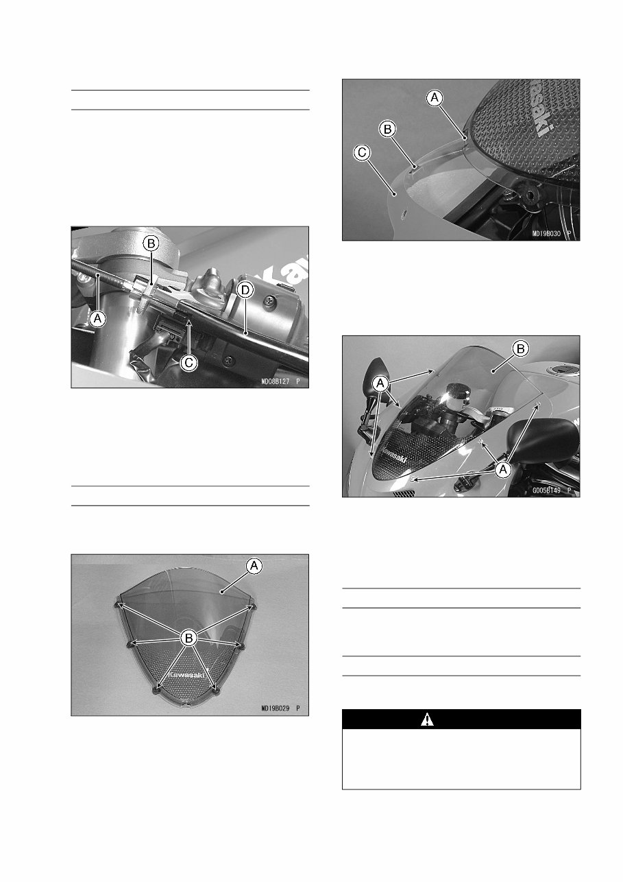
4 ASSEMBLY Parts Check • Open the parts box, and check the parts against the illustrations. There may be mi- nor differences between these illustrations and the actual vehicle parts. In the following charts under Remarks, D = diameter in mil- limeters, and L = length in millimeters. No. Part Name Qty Remarks 1 Steering Stem Head Nut 1 D = 28 2 Plastic Washer 6 D = 5.3 × 11.5 Socket Bolt 6 D = 5, L = 16 Wellnut 6 D=5 Windshield 1 3 Socket Bolt, Rider’s Seat 2 D = 6, L = 16.3 4 Battery Electrolyte, YTX9-BS 1 12 V 8 Ah 5 Owner’s Manual 1 Assembly Steering Stem Head Nut • Remove the steering stem head dummy nut and discard it. Do not remove the steering stem flat washer under the dummy nut. A. Dummy Nut B. Flat Washer • Remove the non-permanent locking agent and clean the steering stem shaft threads. • Install the steering stem head nut (D = 28) on the flat washer with the chamfered side facing upwards and tighten it to the specified torque. Torque: 78 N·m (8.0 kgf·m, 58 ft·lb) A. Chamfered Side of Stem Head Nut B. Flat Washer
ASSEMBLY 5 Clutch Cable • Apply a light coat of grease on the clutch inner cable. • Line up the slots on the clutch lever and ad- juster. • Fit the tip of the clutch inner cable into the lever socket, slide the inner cable through the slots, and release the outer cable into the ad- juster. A. Clutch Cable B. Adjuster C. Cable Tip D. Clutch Lever Windshield • Fit the six wellnuts (D = 5) into the holes in the edge of the windshield from the outside with their flanges out. A. Windshield B. Wellnuts • Put the front tab into the slot of the upper fairing. A. Front Tab B. Slot C. Upper Fairing • Install the six plastic washers and the socket bolts (D = 5, L = 16) on the upper fairing. A. Plastic Washers and Socket Bolts B. Windshield • Tighten the windshield bolts. Do not over tighten the windshield bolts. Rider’s Seat Bolt • Install the rider’s seat bolts. See “Battery Ser- vice” section. Brake Disc Cleaning • Clean the front and rear brake discs using oilless solvent. WARNING If not removed, the anticorrosive treat- ment applied to the brake disc surface will interfere with brake action, and an unsafe riding condition could result.
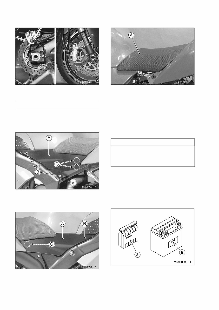
6 PREPARATION Preparation Battery Service Rider’s Seat Removal • Unscrew the left and right side cover bolts (D = 6) (3) and remove the covers by pulling them outward to clear the projections. A. Left Side Cover B. Bolts (D = 6) C. Projections A. Right Side Cover B. Bolt (D = 6) C. Projection • Remove the rider’s seat by pulling the front of it up and forward. A. Rider’s Seat The battery used in this motorcycle is a sealed type and never needs to be refilled. Follow the procedure for activating a new battery to ensure the best possible battery performance. Activating the battery requires two steps, fill- ing the battery with electrolyte, and charging. Read the electrolyte safety label and the follow- ing procedures carefully before battery activa- tion. CAUTION Incorrect Battery Activation will reduce battery performance and service life. Be sure to strictly follow the Battery Service instructions in this Manual. • Make sure to use the electrolyte packed in the crate with the unit. • Make sure that the model name of the elec- trolyte container matches the model name of the battery. These names must be the same. Battery Model Name for ZX636-C1: YTX9-BS A. Model Name of the Electrolyte B. Model Name of the Battery
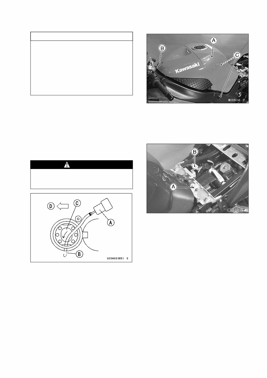
PREPARATION 7 CAUTION Sealed battery electrolyte has a higher concentration of sulfuric acid. Each container contains the proper amount of electrolyte for its specific battery. Insufficient or incorrect electrolyte will reduce battery performance and service life. Electrolyte over capacity can lead to battery cracking or leaking and result in corrosion damage to the vehicle. Battery Removal • Check for fuel in the fuel tank. • If fuel remains in the fuel tank, do the following procedures. • Draw the fuel out from the fuel tank with a commercially available pump. • Use a soft plastic hose as a pump inlet hose in order to insert the hose smoothly. • Put the hose through the filler opening into the tank and draw the fuel out. WARNING The fuel could not be removed com- pletely from the fuel tank. Be careful for remained fuel spillage. A. Commercially Available Pump B. Soft Plastic Hose C. Filler Opening D. Front • Remove the fuel tank bolts (D = 6, D = 8) (3). A. Fuel Tank B. Fuel Tank Bolt (D = 6) C. Fuel Tank Bolts (D = 8) • Remove the fuel tank pivot bolt (D = 6). • Disconnect the fuel pump connector (4P). A. Fuel Tank Pivot Bolt (D = 6) B. Fuel Pump Connector (4P) • Open the fuel tank cap to lower the pressure in the tank. NOTE ○During tank removal, keep the tank cap open to release pressure in the tank. This reduces fuel spillage. • Be sure to place a piece of cloth around the fuel hose joint. • Push the joint lock claws.
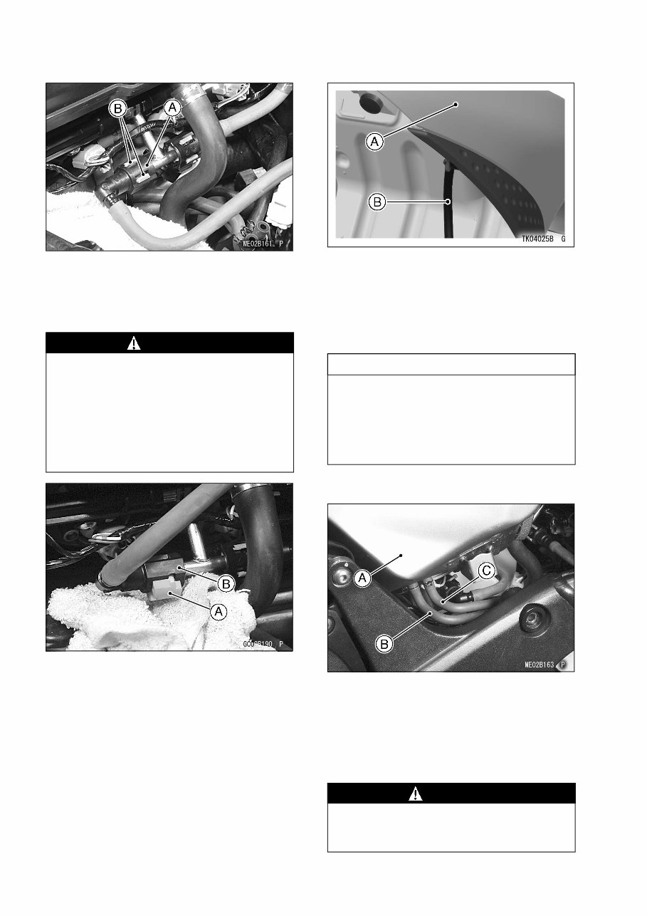
8 PREPARATION A. Fuel Hose Joint B. Joint Lock Claws • Pull the joint lock. • Pull the fuel hose joint out of the delivery pipe. WARNING Be prepared for fuel spillage; any spilled fuel must be completely wiped up imme- diately. When the fuel hose is disconnected, fuel spills out from the hose and the pipe be- cause of residual pressure. Cover the hose connection with a piece of clean cloth to prevent fuel spillage. A. Joint Lock B. Fuel Hose Joint • Remove the drain hose from the fuel tank. A. Fuel Tank B. Drain Hose • Close the fuel tank cap. • Remove the fuel tank, and place it on a flat surface. • For California Model, note the following. CAUTION For California model, if gasoline, sol- vent, water or any other liquid enters the canister, the canister’s vapor absorbing capacity is greatly reduced. If the canis- ter does become contaminated, replace it with a new one. • Remove the fuel return hose (red) and breather hose (blue) from the fuel tank. A. Fuel Tank B. Fuel Return Hose (Red) C. Breather Hose (Blue) • Be sure to plug the evaporative fuel return hose to prevent fuel spilling before fuel tank removal. WARNING For California model, be careful not to spill the gasoline through the return hose. Spilled fuel is hazardous.
Our repair workshop manual covers all models and all repairs from A to Z. It provides vehicle/model-specific information and is the same type of manual used by technicians at local dealerships to maintain, service, diagnose, and repair vehicles. The manual includes complete step-by-step instructions, diagrams, illustrations, wiring schematics, and specifications to facilitate easy vehicle repair. All pages are printable, allowing you to take the necessary information with you to your vehicle or workshop. You can also enlarge and print images as needed.
This factory repair manual is highly detailed and includes complete instructions, illustrations, wiring schematics, and diagrams to fully service and repair your vehicle. It is compatible with Windows 7, Vista 32 and 64, XP, ME, 98, NT, 2000, and Mac computers. The file format is PDF, and the language is English. Instant delivery is available, and the manual is compatible with all versions of Windows PC, tablets, and Mac. Adobe Reader is required for viewing.
With our service repair workshop manual, there are no shipping costs or waiting for a paper or CD manual to arrive in the mail. You will receive the manual today via instant download upon completion of payment through our secure payment processor. We accept all major credit/debit cards and PayPal. By using this manual, you can perform the repairs yourself and save money.
Don't delay – get the repair done today! Click on the green instant download button located at the upper left-hand corner of this page to purchase the service repair workshop manual.
Recently Viewed
5,521,897Happy Clients
2,594,462eManuals
1,120,453Trusted Sellers
15Years in Business
Price:
Actual Price:
2005-2006 Kawasaki Ninja ZX-6R Service & Repair Manual