LIST OF ABBREVIATIONS A ampere(s) lb pound(s) ABDC after bottom dead center m meter(s) AC alternating current min minute(s) ATDC after top dead center N newton(s) BBDC before bottom dead center Pa pascal (s) BDC bottom dead center PS horsepower BTDC before top dead center psi pound(s) per square inch °C degree(s) Celsius r revolution DC direct current rpm revolution(s) per minute F farad (s) TDC top dead center °F degree(s) Fahrenheit TIR total indicator reading ft foot, feet V volt(s) g gram(s) W watt(s) h hour(s) Q ohm(s) L liter(s) This warning may apply to any of the following components or any assembly containing one or more of these components:- Brake Shoes or Pads Clutch Friction Material Gaskets Insulators SAFETY INSTRUCTIONS • Operate if possible out of doors or in a well ventilated place. • Preferably use hand tools or low speed tools equipped, if necessary, with an appropriate dust extraction facility. If high speed tools are used, they should always be so equipped. • If possible, dampen before cutting or drilling. • Dampen dust and place it in properly closed receptacle and dispose of it safely. Read OWNER'S MANUAL before operating.
Foreword This manual is designed primarily for use by trained mechanics in a properly equipped shop. However, it contains enough detail and basic information to make it useful to the owner who desires to perform his own basic maintenance and repair work. A basic knowledge of mechanics, the proper use of tools, and workshop procedures must be understood in order to carry out maintenance and repair satisfactorily. Whenever the owner has insufficient experience or doubts his ability to do the work, all adjustments, maintenance, and repair should be carried out only by qualified mechanics. In order to perform the work efficiently and to avoid costly mistakes, read the text, thoroughly familiarize yourself with the procedures before starting work, and then do the work carefully in a clean area. Whenever special tools or equipment are specified, do not use makeshift tools or equipment. Precision measurements can only be made if the proper instruments are used, and the use of substi- tute tools may adversely affect safe operation. For the duration of the warranty period, we recommend that all repairs and scheduled maintenance be performed in accordance with this service manual. Any owner maintenance or repair procedure not performed in accordance with this manual may void the warranty. To get the longest life out of your "JET SKI" watercraft: • Follow the Periodic Maintenance Chart in the Service Manual. • Be alert for problems and non-scheduled mainte- nance. • Use proper tools and genuine Kawasaki "JET SKI" watercraft parts. Special tools, gauges, and testers that are necessary when servicing Kawasaki "JET SKI" watercraft are introduced by the Special Tool Manual. Genuine part provided as spare parts are listed in the Parts Catalog. • Follow the procedures in this manual carefully. Don't take shortcuts. • Remember to keep complete records of mainte- nance and repair with dates and any new parts installed. How to Use this Manual In preparing this manual, we divided the product into its major systems. These systems became the manual's chapters. All information for a particular system from adjustment through disassembly and inspection is located in a single chapter. The Quick Reference Guide shows you all of the product's system and assists in locating their chapters. Each chapter in turn has its own compre- hensive Table of Contents. The Periodic Maintenance Chart is located in the General Information chapter. The chart gives a time schedule for required maintenance operations. If you want spark plug information, for example, go to the Periodic Maintenance Chart first. The chart tells you how frequently to clean and gap the plug. Next, use the Quick Reference Guide to locate the Electrical System chapter. Then, use the Table of Contents on the first page of the chapter to find the Spark Plug section. Whenever you see these WARNING and CAUTION symbols, heed their instructions! Always follow safe operating and maintenance practices. This warning symbol identifies special instructions or procedures which, if not correctly followed, could result in personal injury, or loss of life. This caution symbol identifies special instructions or procedures which, if not strictly observed, could result in damage to or destruction of equipment.
This manual contains four more symbols (in addition to WARNING and CAUTION) which will help you distinguish different types of information. NOTE o This note symbol indicates points of partic- ular interest for more efficient and convenient operation. • Indicates a procedural step or work to be done. o Indicates a procedural sub-step or how to do the work of the procedural step it follows. It also precedes the text of a NOTE. * Indicates a conditional step or what action to take based on the results of the test or inspection in the procedural step or sub-step it follows. In most chapters an exploded view illustration of the system components follows the Table of Contents. In these illustrations you will find the instructions indicating which parts require specified tightening torque, oil, grease or a locking agent during assembly.
EMISSION CONTROL ll\lFORMATION To protect the environment in which we all live, Kawasaki has incorporated crankcase emission (1) and exhaust emission (2) control systems in compliance with applicable regulations of the United States Environmental Protection Agency and California Air Resources Board. Additionally, Kawasaki has incorporated an evaporative emission control system (3) in compliance with applicable regulations of the California Air Resources Board on vehicles sold in California only. 1. Crankcase Emission Control System This system eliminates the release of crankcase vapors into the atmosphere. Instead, the vapors are routed through an oil separator to the intake side of the engine. While the engine is operating, the vapors are drawn into combustion chamber, where they are burned along with the fuel and air supplied by the carburetion system. 2. Exhaust Emission Control System This system reduces the amount of pollutants discharged into the atmosphere by the exhaust of this motorcycle. The fuel and ignition systems of this motorcycle have been carefully designed and constructed to ensure an efficient engine with low exhaust pollutant levels. 3. Evaporative Emission Control System Vapors caused by fuel evaporation in the fuel system are not vented into the atmosphere. Instead, fuel vapors are routed into the running engine to be burned, or stored in a canister when the engine is stopped. Liquid fuel is caught by a vapor separator and returned to the fuel tank. The Clean Air Act, which is the Federal law covering motor vehicle pollution, contains what is commonly referred to as the Act's "tampering provisions." "Sec. 203(a) The following acts and the causing thereof are prohibited... (3) (A) for any person to remove or render inoperative any device or element of design installed on or in a motor vehicle or motor vehicle engine in compliance with regulations under this title prior to its sale and delivery to the ultimate purchaser, or for any manufacturer or dealer knowingly to remove or render inoperative any such device or element of design after such sale and delivery to the ultimate purchaser. (3)(B) for any person engaged in the business of repairing, servicing, selling, leasing, or trading motor vehicles or motor vehicle engines, or who operates a fleet of motor vehicles knowingly to remove or render inoperative any device or element of design installed on or in a motor vehicle or motor vehicle engine in compliance with regulations under this title following its sale and delivery to the ultimate purchaser..." (Continued on next page.)
NOTE o The phrase "remove or render inoperative any device or element of design" has been generally interpreted as follows: 1. Tampering does not include the temporary removal or rendering inoperative of devices or elements of design in order to perform maintenance. 2. Tampering could include: a. Maladjustment of vehicle components such that the emission standards are exceeded. b. Use of replacement parts or accessories which adversely affect the performance or durability of the motorcycle. c. Addition of components or accessories that result in the vehicle exceeding the standards. d. Permanently removing, disconnecting, or rendering inoperative any component or element of design of the emission control systems. WE RECOMMEND THAT ALL DEALERS OBSERVE THESE PROVISIONS OF FEDERAL LAW, THE VIOLATION OF WHICH IS PUNISHABLE BY CIVIL PENALTIES NOT EXCEEDING $10,000 PER VIOLATION. TAMPERING WITH NOISE CONTROL SYSTEM PROHIBITED Federal law prohibits the following acts or the causing thereof: (1) The removal or rendering inoperative by any person other than for purposes of maintenance, repair, or replacement, of any device or element of design incorporated into any new vehicle for the purpose of noise control prior to its sale or delivery to the ultimate purchaser or while it is in use, or (2) the use of the vehicle after such device or element of design has been removed or rendered inoperative by any person. Among those acts presumed to constitute tampering are the acts listed below: • Replacement of the original exhaust system or muffler with a component not in compliance with Federal regulations. • Removal of the muffler(s) or any internal portion of the muffler(s). • Removal of the air box or air box cover. • Modifications to the muffler(s) or air intake system by cutting, drilling, or other means if such modifications result in increased noise levels.
Quick Reference Guide This quick reference guide will assist you in locating a desired topic or procedure. • Bend the pages back to match the black tab of the desired chapter number with the black tab on the edge at each table of contents page. • Refer to the sectional table of contents for the exact pages to locate the specific topic required. General Information Fuel System Cooling System Engine Top End Engine Right Side/Left Side Engine Lubrication System Engine Removal/Installation Crankshaft/Transmission Wheels/Tires Final Drive Brakes Suspension Steering Frame Electrical System Appendix Supplement -1994 Models
GENERAL INFORMATION 1-1 General Information Table of Contents Before Servicing 1-1 Model Identification 1 -4 General Specifications 1 -6 Periodic Maintenance Chart - KLX250D 1-10 Periodic Maintenance Chart - KLX250E 1 -12 Torque and Locking Agent 1 -14 Special Tools and Sealant 1-17 Cable, Wire and Hose Routing 1 -23
1-2 GENERAL INFORMATION Before Servicing Before starting to service a motorcycle, careful reading of the applicable section is recommended to eliminate unnecessary work. Photographs, diagrams, notes, cautions, warnings, and detailed descriptions have been included wherever necessary. Nevertheless, even a detailed account has limitations, a certain amount of basic knowledge is also required for successful work. Especially note the following: (1) Dirt Before removal and disassembly, clean the motorcycle. Any dirt entering the engine or other parts will work as an abrasive and shorten the life of the motorcycle. For the same reason, before installing a new part, clean off any dust or metal filings. (2) Battery Ground Remove the ground (-) lead from the battery before performing any disassembly operations on the motorcycle. This prevents: (a) the possibility of accidentally turning the engine over while partially disassembled. (b) sparks at electrical connections which will occur when they are disconnected. (c) damage to electrical parts. (3) Tightening Sequence Generally, when installing a part with several bolts, nuts, or screws, start them all in their holes and tighten them to a snug fit. Then tighten them evenly in a cross pattern. This is to avoid distortion of the part and/or causing gas or oil leakage. Conversely when loosening the bolts, nuts, or screws, first loosen all of them by about a quarter turn and then remove them. Where there is a tightening sequence indication in this Service Manual, the bolts, nuts, or screws must be tightened in the order and method indicated. (4) Torque When torque values are given in this Service Manual, use them. Either too little or too much torque may lead to serious damage. Use a good quality, reliable torque wrench. (5) Force Common sense should dictate how much force is necessary in assembly and disassembly. If a part seems especially difficult to remove or install, stop and examine what may be causing the problem. Whenever tapping is necessary, tap lightly using a wooden or plastic-faced mallet. Use an impact driver for screws (particularly for the removal of screws held by a locking agent) in order to avoid damaging the screw heads. (6) Edges Watch for sharp edges, especially during major engine disassembly and assembly. Protect your hands with gloves or a piece of thick cloth when lifting the engine or turning it over. (7) High-Flash Point Solvent A high-flash point solvent is recommended to reduce fire danger. A commercial solvent commonly available in North America is Stoddard solvent (generic name). Always follow manufacturer and container directions regarding the use of any solvent. (8) Gasket, 0-Ring Do not reuse a gasket or O-ring once it has been in service. The mating surfaces around the gasket should be free of foreign matter and perfectly smooth to avoid oil or compression leaks. (9) Liquid Gasket, Non-Permanent Locking Agent Follow manufacturer's directions for cleaning and preparing surfaces where these compounds will be used Apply sparingly. Excessive amounts may block engine oil passages and cause serious damage. An example of a non-permanent locking agent commonly available in North America is Loctite Lock'n Seal (Blue). (10) Press . A part installed using a press or driver, such as a wheel bearing, should first be coated with oil on its outer or inner circumference so that it will go into place smoothly. (11) Ball Bearing and Needle Bearing Do not remove any ball or needle bearings that are pressed in unless it is necessary. If they are removed, replace them with new ones. When installing a bearing, press it in with the marked side facing out using a suitable driver until it is bottomed. Bearings should be pressed into place by pushing evenly the bearing race which is affected by friction.
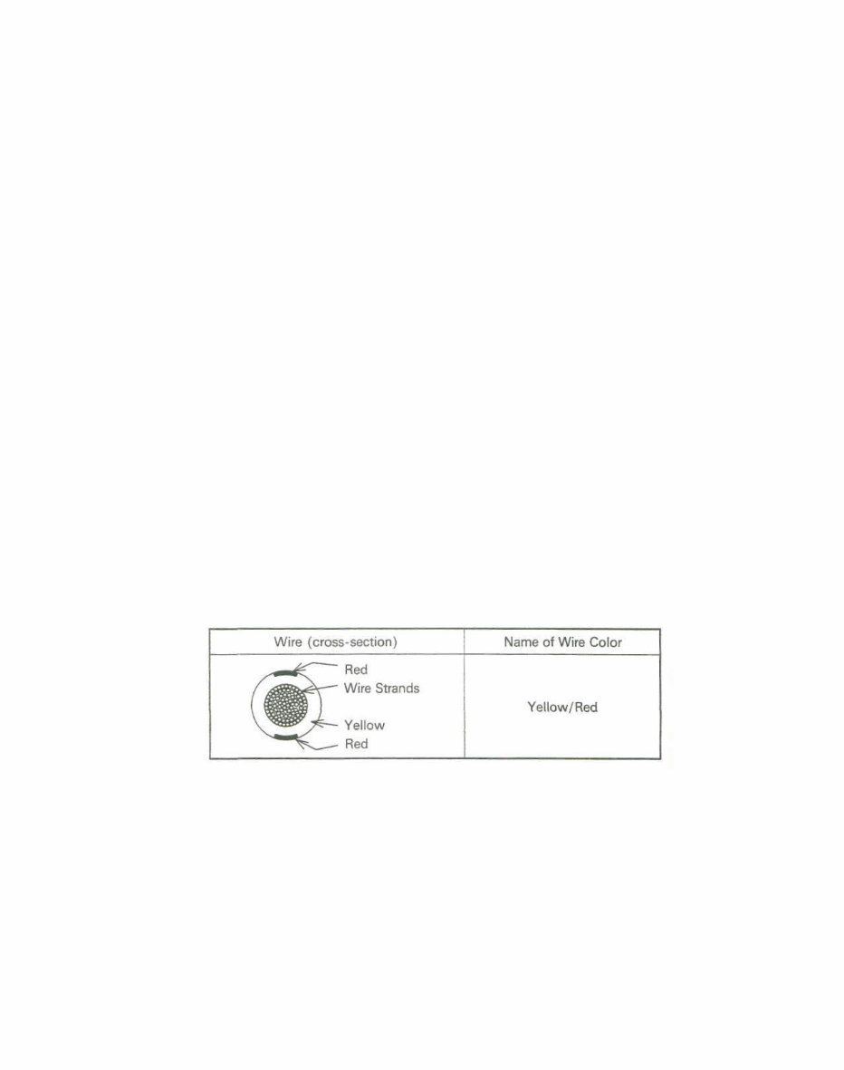
GENERAL INFORMATION 1-3 (12) Oil Seal and Grease Seal Replace any oil or grease seals that were removed with new ones, as removal generally damages seals. When pressing in a seal which has manufacturer's marks, press it in with the marks facing out. Seals should be pressed into place using a suitable driver, which contacts evenly with the side of seal, until the face of the seal is even with the end of the hole. (13) Seal Guide A seal guide is required for certain oil or grease seals during installation to avoid damage to the seal lips. Before a shaft passes through a seal, apply a little high temperature grease on the lips to reduce rubber to metal friction. (14) Circlip, Retaining Ring Replace any circlips and retaining rings that were removed with new ones, as removal weakens and deforms them. When installing circlips and retaining rings, take care to compress or expand them only enough to install them and no more. (15) Cotter Pin Replace any cotter pins that were removed with new ones, as removal deforms and breaks them. (16) Lubrication Engine wear is generally at its maximum while the engine is warming up and before all the rubbing surfaces have an adequate lubricative film. During assembly, oil or grease (whichever is more suitable) should be applied to any rubbing surface which has lost its lubricative film. Old grease and dirty oil should be cleaned off. Deteriorated grease has lost its lubricative quality and may contain abrasive foreign particles. Don't use just any oil or grease. Some oils and greases in particular should be used only in certain applications and may be harmful if used in an application for which they are not intended. This manual makes reference to molybdenum disulfide grease (M0S2 ) in the assembly of certain engine and chassis parts. Always check manufacturer recommendations before using such special lubricants. (17) Electrical Wires All the electrical wires are either single-color or two-color and, with only a few exceptions, must be connected to wires of the same color. On any of the two-color wires there is a greater amount of one color and a lesser amount of a second color, so a two-color wire is identified by first the primary color and then the secondary color. For example, a yellow wire with thin red stripes is referred to as a "yellow/red" wire; it would be a "red/yellow" wire if the colors were reversed to make red the main color. (18) Replacement Parts When there is a replacement instruction, replace these parts with new ones every time they are removed. These replacement parts will be damaged or lose their original function once removed. (19) Inspection When parts have been disassembled, visually inspect these parts for the following conditions or other damage. If there is any doubt as to the condition of them, replace them with new ones. Abrasion Crack Hardening Warp Bent Dent Scratch Wear Color change Deterioration Seizure (20) Specifications Specification terms are defined as follows: "Standards" show dimensions or performances which brand-new parts or systems have. "Service Limits" indicate the usable limits. If the measurement shows excessive wear or deteriorated performance, replace the damaged parts.
Looking for a comprehensive service workshop manual for your KAWASAKI KLX 250? Look no further. This manual is designed for easy readability and contains highly detailed exploded pictures, diagrams, and step-by-step instructions. It provides in-depth insights into your motorcycle, and all pages are printable, making it a valuable resource for professional mechanics and DIY enthusiasts alike.
The Service Repair Manual covers a wide range of topics including General Information, Fuel System, Cooling System, Engine Top End, Engine Lubrication System, Engine Removal/Installation, Crankshaft/Transmission, Wheels/Tires, Final Drive, Brakes, Suspension, Steering, Frame, and Electrical System.
Obtaining this manual is quick and convenient. Upon completing the purchase, you can instantly access it, saving both time and money. Additionally, there's no need to worry about extra costs or waiting for delivery.