This quick reference guide will assist you in locating a desired topic or pro- cedure. •Bend the pages back to match the black tab of the desired chapter num- ber with the black tab on the edge at each table of contents page. •Refer to the sectional table of contents for the exact pages to locate the spe- cific topic required. Quick Reference Guide General Information 1 Periodic Maintenance 2 Fuel System 3 Engine Top End 4 Clutch 5 Engine Lubrication System 6 Engine Removal/Installation 7 Crankshaft/Transmission 8 Wheels/Tires 9 Final Drive 10 Brakes 11 Suspension 12 Steering 13 Frame 14 Electrical System 15 Appendix 16
KLX140 KLX140L Motorcycle Service Manual
LIST OF ABBREVIATIONS A ampere(s) lb pound(s) ABDC after bottom dead center m meter(s) AC alternating current min minute(s) ATDC after top dead center N newton(s) BBDC before bottom dead center Pa pascal(s) BDC bottom dead center PS horsepower BTDC before top dead center psi pound(s) per square inch °C degree(s) Celsius r revolution DC direct current rpm revolution(s) per minute F farad(s) TDC top dead center °F degree(s) Fahrenheit TIR total indicator reading ft foot, feet V volt(s) g gram(s) W watt(s) h hour(s) Ω ohm(s) L liter(s) COUNTRY AND AREA CODES AU Australia US United States CA Canada KLX140A model is designed for a rider weighting less than 154 pounds (70 kg). Exceeding this limit could damage the motorcycle.
EMISSION CONTROL INFORMATION To protect the environment in which we all live, Kawasaki has incorporated crankcase emis- sion (1) and exhaust emission (2) control systems in compliance with applicable regulations of the United States Environmental Protection Agency and California Air Resources Board. Addi- tionally, Kawasaki has incorporated an evaporative emission control system (3) in compliance with applicable regulations of the United States Environmental Protection Agency. 1. Crankcase Emission Control System This system eliminates the release of crankcase vapors into the atmosphere. Instead, the vapors are routed through an oil separator to the intake side of the engine. While the engine is operating, the vapors are drawn into the combustion chamber, where they are burned along with the fuel and air supplied by the fuel injection system. 2. Exhaust Emission Control System This system reduces the amount of pollutants discharged into the atmosphere by the exhaust of this vehicle. The fuel, ignition and exhaust systems of this vehicle have been carefully de- signed and constructed to ensure an efficient engine with low exhaust pollutant levels. 3. Evaporative Emission Control System The evaporative emission control system for this vehicle consists of low permeation fuel hoses and a fuel tank. The Clean Air Act, which is the Federal law covering motor vehicle pollution, contains what is commonly referred to as the Act’s “tampering provisions”. “Sec. 203(a) The following acts and the causing thereof are prohibited. (3)(A) for any person to remove or render inoperative any device or element of design installed on or in a motor vehicle or motor vehicle engine in compliance with regulations under this title prior to its sale and delivery to the ultimate purchaser, or for any manufacturer or dealer knowingly to remove or render inoperative any such device or element of design after such sale and delivery to the ultimate purchaser. (3)(B) for any person engaged in the business of repairing, servicing, selling, leasing, or trading motor vehicles or motor vehicle engines, or who operates a fleet of motor vehicles know- ingly to remove or render inoperative any device or element of design installed on or in a motor vehicle or motor vehicle engine in compliance with regulations under this title follow- ing its sale and delivery to the ultimate purchaser...” NOTE ○ The phrase “remove or render inoperative any device or element of design” has been generally interpreted as follows. 1. Tampering does not include the temporary removal or rendering inoperative of de- vices or elements of design in order to perform maintenance. 2. Tampering could include. a.Maladjustment of vehicle components such that the emission standards are ex- ceeded. b.Use of replacement parts or accessories which adversely affect the performance or durability of the motorcycle. c.Addition of components or accessories that result in the vehicle exceeding the stan- dards. d.Permanently removing, disconnecting, or rendering inoperative any component or element of design of the emission control systems. WE RECOMMEND THAT ALL DEALERS OBSERVE THESE PROVISIONS OF FEDERAL LAW, THE VIOLATION OF WHICH IS PUNISHABLE BY CIVIL PENALTIES NOT EXCEEDING $10 000 PER VIOLATION.
TAMPERING WITH NOISE CONTROL SYSTEM PROHIBITED Federal law prohibits the following acts or the causing thereof. (1) The removal or rendering inoperative by any person other than for purposes of maintenance, repair, or replacement, of any device or element of design incorporated into any new vehicle for the purpose of noise control prior to its sale or delivery to the ultimate purchaser or while it is in use, or (2) the use of the vehicle after such device or element of design has been removed or rendered inoperative by any person. Among those acts presumed to constitute tampering are the acts listed below. • Replacement of the original exhaust system or muffler with a component not in compliance with Federal regulations. • Removal of the muffler or any internal portion of the muffler. • Removal of the air box or air box cover. • Modifications to the muffler or air intake system by cutting, drilling, or other means if such modifications result in increased noise levels.
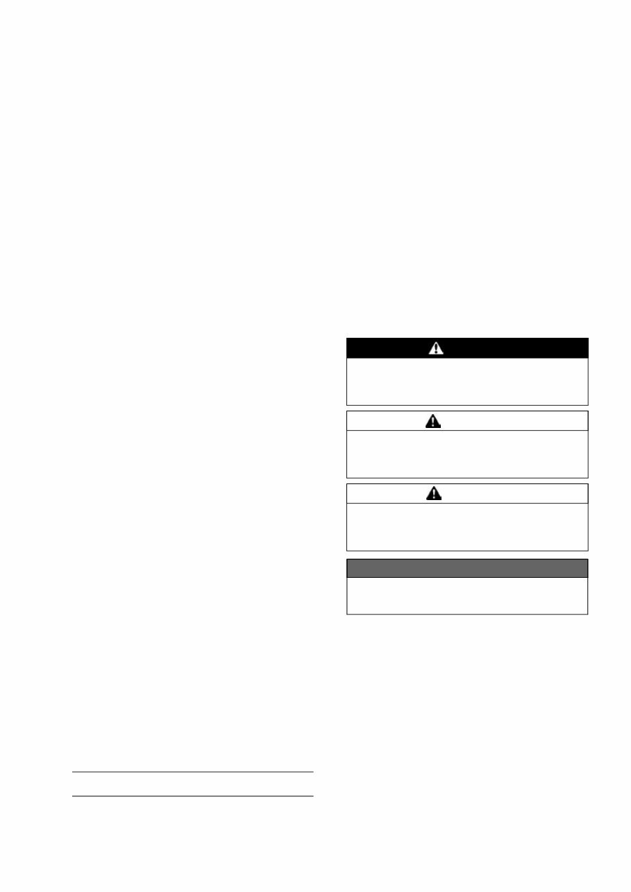
Foreword This manual is designed primarily for use by trained mechanics in a properly equipped shop. However, it contains enough detail and basic in- formation to make it useful to the owner who de- sires to perform his own basic maintenance and repair work. A basic knowledge of mechanics, the proper use of tools, and workshop proce- dures must be understood in order to carry out maintenance and repair satisfactorily. When- ever the owner has insufficient experience or doubts his ability to do the work, all adjust- ments, maintenance, and repair should be car- ried out only by qualified mechanics. In order to perform the work efficiently and to avoid costly mistakes, read the text, thor- oughly familiarize yourself with the procedures before starting work, and then do the work care- fully in a clean area. Whenever special tools or equipment are specified, do not use makeshift tools or equipment. Precision measurements can only be made if the proper instruments are used, and the use of substitute tools may ad- versely affect safe operation. For the duration of the warranty period, we recommend that all repairs and scheduled maintenance be performed in accordance with this service manual. Any owner maintenance or repair procedure not performed in accordance with this manual may void the warranty. To get the longest life out of your vehicle: • Follow the Periodic Maintenance Chart in the Service Manual. • Be alert for problems and non-scheduled maintenance. • Use proper tools and genuine Kawasaki Mo- torcycle parts. Special tools, gauges, and testers that are necessary when servicing Kawasaki motorcycles are introduced by the Service Manual. Genuine parts provided as spare parts are listed in the Parts Catalog. • Follow the procedures in this manual care- fully. Don’t take shortcuts. • Remember to keep complete records of main- tenance and repair with dates and any new parts installed. How to Use This Manual In this manual, the product is divided into its major systems and these systems make up the manual’s chapters. The Quick Reference Guide shows you all of the product’s system and assists in locating their chapters. Each chapter in turn has its own comprehensive Ta- ble of Contents. For example, if you want ignition coil informa- tion, use the Quick Reference Guide to locate the Electrical System chapter. Then, use the Table of Contents on the first page of the chap- ter to find the Ignition Coil section. Whenever you see symbols, heed their in- structions! Always follow safe operating and maintenance practices. DANGER DANGER indicates a hazardous situa- tion which, if not avoided, will result in death or serious injury. WARNING WARNING indicates a hazardous situa- tion which, if not avoided, could result in death or serious injury. CAUTION CAUTION indicates a hazardous situa- tion which, if not avoided, could result in minor or moderate injury. NOTICE NOTICE is used to address practices not related to personal injury. This manual contains four more symbols which will help you distinguish different types of information. NOTE ○ This note symbol indicates points of par- ticular interest for more efficient and con- venient operation. • Indicates a procedural step or work to be done. ○ Indicates a procedural sub-step or how to do the work of the procedural step it follows. It also precedes the text of a NOTE.
Indicates a conditional step or what action to take based on the results of the test or inspec- tion in the procedural step or sub-step it fol- lows. In most chapters an exploded view illustration of the system components follows the Table of Contents. In these illustrations you will find the instructions indicating which parts require spec- ified tightening torque, oil, grease or a locking agent during assembly.
GENERAL INFORMATION 1-1 1 General Information Table of Contents Before Servicing ..................................................................................................................... 1-2 Model Identification................................................................................................................. 1-7 General Specifications............................................................................................................ 1-9 Unit Conversion Table ............................................................................................................ 1-12
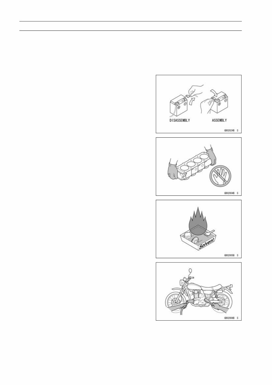
1-2 GENERAL INFORMATION Before Servicing Before starting to perform an inspection service or carry out a disassembly and reassembly opera- tion on a motorcycle, read the precautions given below. To facilitate actual operations, notes, illustra- tions, photographs, cautions, and detailed descriptions have been included in each chapter wherever necessary. This section explains the items that require particular attention during the removal and reinstallation or disassembly and reassembly of general parts. Especially note the following: Battery Ground Before completing any service on the motorcycle, discon- nect the battery cables from the battery to prevent the en- gine from accidentally turning over. Disconnect the ground cable (–) first and then the positive (+). When completed with the service, first connect the positive (+) cable to the positive (+) terminal of the battery then the negative (–) ca- ble to the negative terminal. Edges of Parts Lift large or heavy parts wearing gloves to prevent injury from possible sharp edges on the parts. Solvent Use a high-flash point solvent when cleaning parts. High -flash point solvent should be used according to directions of the solvent manufacturer. Cleaning vehicle before disassembly Clean the vehicle thoroughly before disassembly. Dirt or other foreign materials entering into sealed areas during ve- hicle disassembly can cause excessive wear and decrease performance of the vehicle.
You're Reading a Preview
What's Included?
Lifetime Access
Fast Download Speeds
Online & Offline Access
Access PDF Contents & Bookmarks
Full Search Facility
Print one or all pages of your manual
$28.99
2008-2011 Kawasaki KLX140, KLX140L Service Repair Workshop Manual
This is a highly detailed factory service repair manual for the 2008-2011 Kawasaki KLX140, KLX140L. The service manual has detailed illustrations as well as step-by-step instructions, making it 100% complete and intact. It is specifically written for the do-it-yourself-er as well as the experienced mechanic. The 2008-2011 Kawasaki KLX140, KLX140L Service Repair Workshop Manual provides step-by-step instructions based on the complete disassembly of the machine. This level of detail, along with hundreds of photos and illustrations, guides the reader through each service and repair procedure. The manual comes in PDF format, which can work under all PC-based Windows operating systems and Mac as well. All pages are printable. Using this repair manual is an inexpensive way to keep your vehicle working properly.
Models Covers:
2008 Kawasaki KLX140A8F
2008 Kawasaki KLX140B8F
2009 Kawasaki KLX140A9F
2009 Kawasaki KLX140B9F
2010 Kawasaki KLX140AAF
2010 Kawasaki KLX140BAF
2011 Kawasaki KLX140ABF
2011 Kawasaki KLX140BBF
Service Repair Manual Covers:
General Information
Periodic Maintenance
Fuel System
Engine Top End
Clutch
Engine Lubrication System
Engine Removal/Installation
Crankshaft/Transmission
Wheels/Tires
Final Drive
Brakes
Suspension
Steering
Frame
Electrical System
Appendix
And More......
File Format: PDF
Compatible: All Versions of Windows & Mac
Language: English
Requirements: Adobe Reader & WinZip
No waiting, buy from a responsible seller and get instant access, without wasting your hard-owned money on uncertainty or surprise! All pages are printable. It is great to have the 2008-2011 Kawasaki KLX140, KLX140L Service Repair Workshop Manual.
Reviews
Q&A
Recently Viewed
5,521,897Happy Clients
2,594,462eManuals
1,120,453Trusted Sellers
15Years in Business
Price:
Actual Price:
2008-2011 Kawasaki KLX140, KLX140L Service Repair Workshop Manual