

1983-1985 Kawasaki GPZ 400-500-550 Service & Repair Manual
What's Included?
Fast Download Speeds
Online & Offline Access
Access PDF Contents & Bookmarks
Full Search Facility
Print one or all pages of your manual
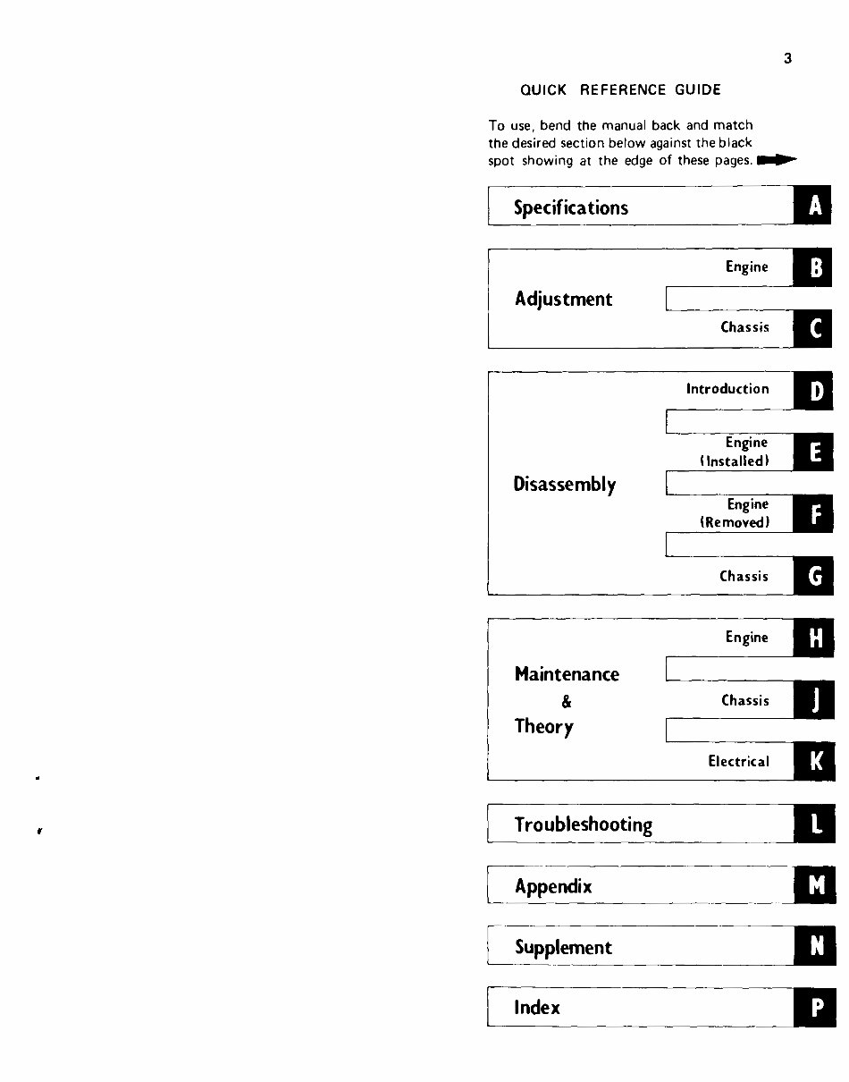
QUICK REFERENCE GUIDE
To use, bend the manual back and match
the desired section below against the black
spot showing at the edge of these pages.
Specifications
1 Adiustment 1
Introduction
Disassembly
I
Chassis
Engine
r
Maintenance
& Chassis
Theory
Electrical
Troubleshooting
Appendix
-
Supplement
Index
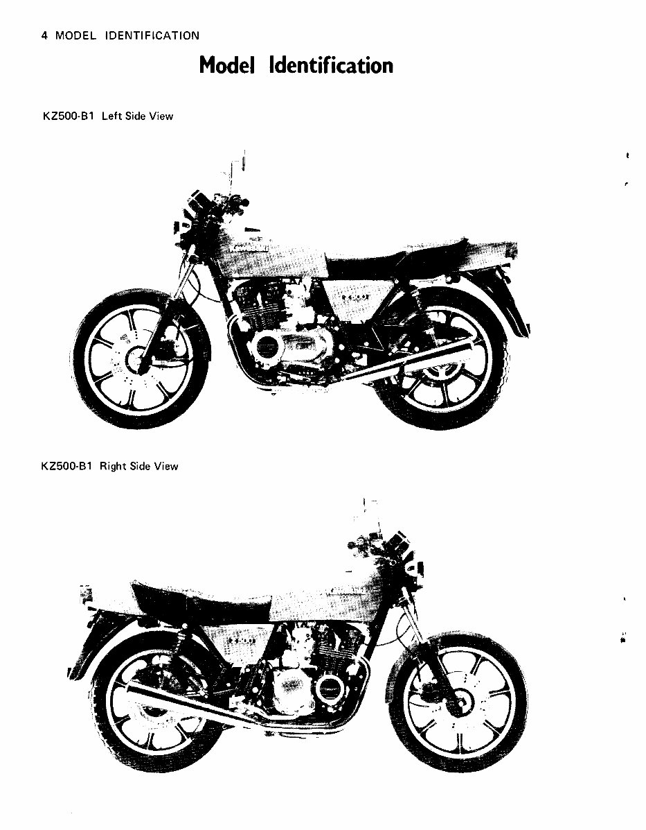
4 MODEL IDENTIFICATION
Model ldentification
KZ500-B1 Left Side View
KZ500-B1 Right Side View
SPECIFICATIONS 5
Specifications
Table of Contents
SPECIFICATIONS .......................................... 6
ENGINE PERFORMANCE CURVES ........................... 8
RUNNING PERFORMANCE CURVES ......................... 9
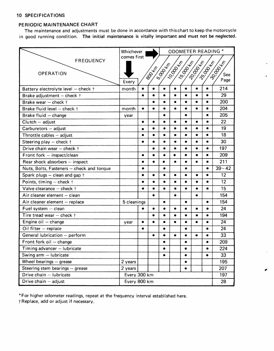
........................... PERIODIC MAINTENANCE CHART 10
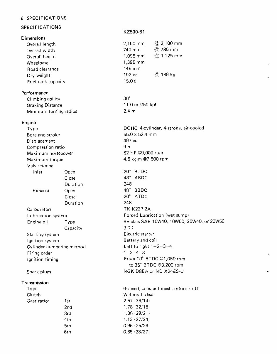
6 SPECIFICATIONS
SPEC1 FICATIONS
Dimensions
Overall length
Overall width
Overall height
Wheel base
Road clearance
Dry weight
Fuel tank capacity
Performance
Climbing ability
Braking Distance
Minimum turning radius
Engine
TY pe
Bore and stroke
Displacement
Compression ratio
Maximum horsepower
Maximum torque
Valve timing
Inlet Open
Close
Duration
Exhaust Open
Close
Duration
Carburetors
Lubrication system
Engine oil TY pe
Capacity
Starting system
Ignition system
Cylinder numbering method
Firing order
Ignition timing
Spark plugs
Transmission
TY pe
Clutch
Gear ratio: 1 st
2nd
3rd
4th
5th
6th
DOHC, 4-cylinder, 4-stroke, air-cooled
55.0 x 52.4 mm
497 cc
9.5
52 HP (99,000 rpm
4.5 kg-m @7,500 rpm
20" BTDC
48" ABDC
248"
48" BBDC
20" ATDC
248"
TK K22P-2A
Forced Lubrication (wet sump)
SE class SAE 10W40, 10W50, 20W40, or 20W50
3.0 a
Electric starter
Battery and coil
Left to right 1-2-3-4
1-2-4-3
From 10" BTDC (91,050 rpm
to 35" BTDC (93,200 rpm
NGK D8EA or ND X24ES-U
6-speed, constant mesh, return shift
Wet rnulti disc
2.57 (36114)
1.78 ( W l 8 )
1.38 (29121 )
1.13 (27124)
0.96 (25126)
0.85 (23127)
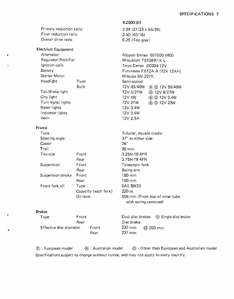
Primary reduction ratio
Final reduction ratio
Overall drive ratio
Electrical Equipment
Alternator
Regulator/Rectifier
Ignition coils
Battery
Starter Motor
Headlight
TailIBrake light
City light
Turn signal lights
Meter lights
Indicator lights
Horn
Frame
TY pe
Steering angle
Castor
Trail
Tire size
Suspension
Suspension stroke
Front fork oil
Brakes
TY pe
TY pe
Bulb
Front
Rear
Front
Rear
Front
Rear
TY pe
Capacity (each fork)
Oil level
Front
Rear
Effective disc diameter Front
Rear
KZ500-61
2.94 (27123 x 65/26)
2.50 (40116)
6.25 (Top gear)
Nippon Denso 037000-1400
Mitsubishi TSIOBRI K-L
Toyo Denso ZC004-12V
Furukawa FB12A-A (12V 12AH)
Mitsuba SM-227K
Semi-sealed
12v 45/40w @ @l 1 2 v 50140W
12V 5/21 W 0 12V 8/27W
12v 4W @ 0 12v 3.4W
12V21W @@12V23W
12v 3.4W
12v 3.4W
12V 2.5A
Tubular, double cradle
37" to either side
26"
98 mm
3.25H-19 4PR
3.75H-18 4PR
Telescopic fork
Swing arm
180 mm
100 mm
SAE 5W20
220 cc
505 mm (From top of inner tube
with spring removed)
Dual disc brakes 0 Single disc brake
Disc brake
232 mm @I 250 mm
237 mm
@ : European model @ : Australian model 0 : Other than European and Australian model
Specifications subject to change without notice, and may not apply to every country.
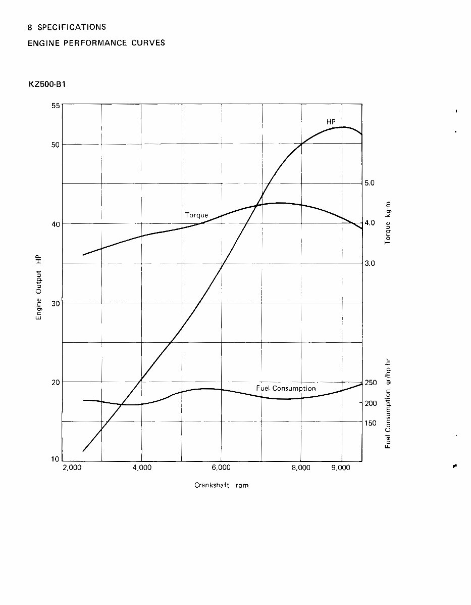
8 SPECIFICATIONS
ENGINE PERFORMANCE CURVES
Crankshaft rprn
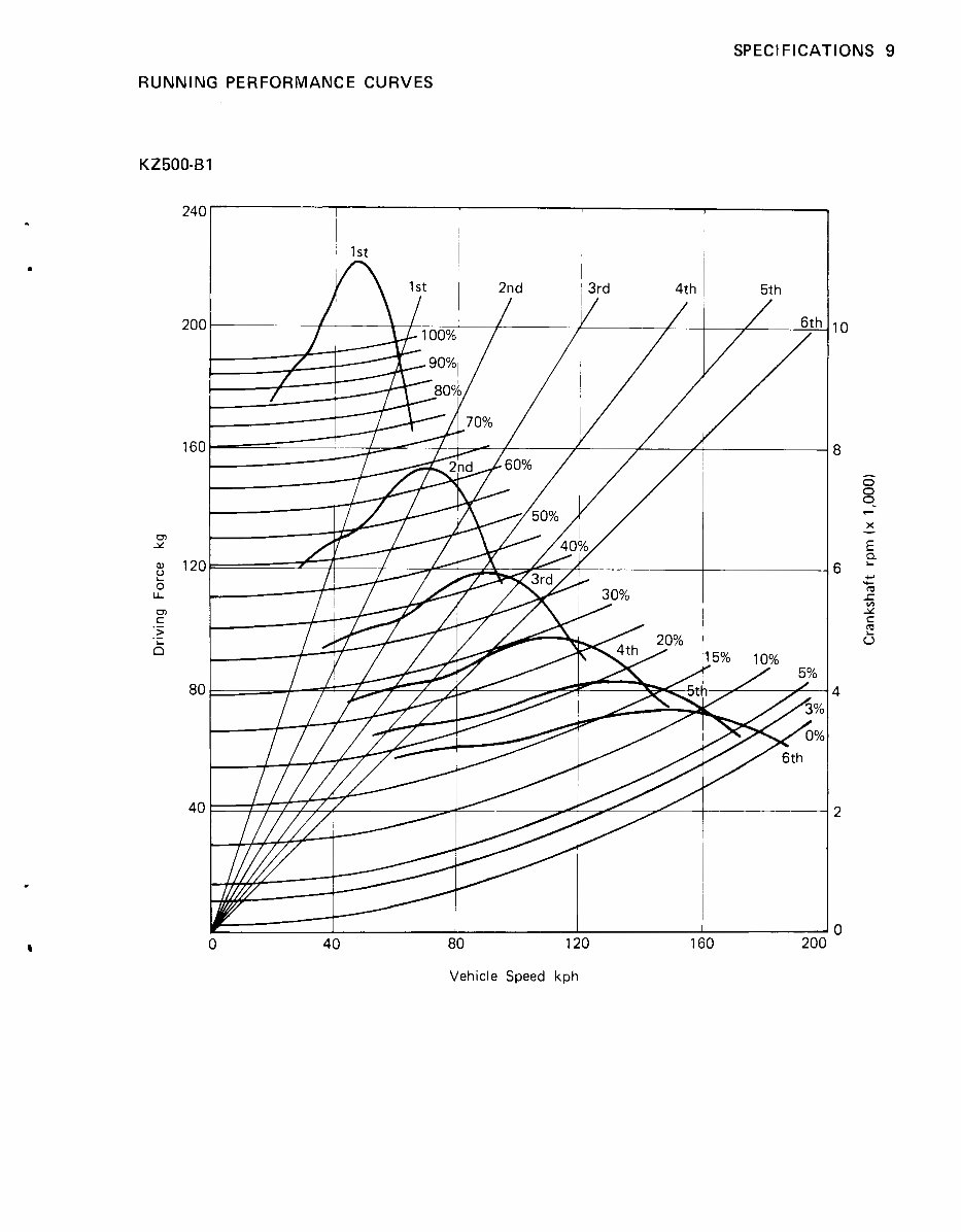
SPECIFICATIONS 9
RUNNING PERFORMANCE CURVES
I:'
1 I I I
4 0 80 120 160 201
Vehicle Speed kph
ADJUSTMENT.. ENGINE 11
Adjustment-Engine
Table of Contents
SPARK PLUGS ............................................ 12
IGNITION TIMING ......................................... 12
Point Gap Adjustment (using a thickness gauge) ................. 13
Point Gap Adjustment (using a dwell angle tester) ................ 13
....................................... Timing Test (Static) 13
.................................... Timing Test (Dynamic) 14
...................................... VALVE CLEARANCE 15
THROTTLE CABLES ....................................... 18
........................................... CARBURETORS 19
........................... Initial Synchronization-Mechanical 19
........................................ Idling Adjustment 21
...................................... Fine Synchronization 21
CLUTCH ................................................ 22
ENGINE OIL .............................................. 24
....................................... Oil Level Inspection 24
................................... Oil and Oil Filter Change 24
............................................ FUEL SYSTEM 24
12 ADJUSTMENT-ENGINE
SPARK PLUGS Correct ignition timing is achieved by first obtaining
Neglecting the spark plug eventually leads to difficult
starting and poor performance. If the spark plug is used
for a long period, the electrodes gradually burn away
and carbon builds up along the insulator. In accordance
with the Periodic Maintenance Chart (Pg. lo), the plug
should be removed for inspection, cleaning and to reset
the gap.
@Remove the spark plugs using a spark plug wrench.
@Clean the spark plug preferably in a sand-blasting
device, and then clean off any abrasive particles. The
plug may also be cleaned using a high flash-point
solvent and a wire brush or other suitable tool. If the
spark plug electrodes are corroded or damaged, or if
the insulator is cracked, replace the plug. Use the
standard plug or its equivalent.
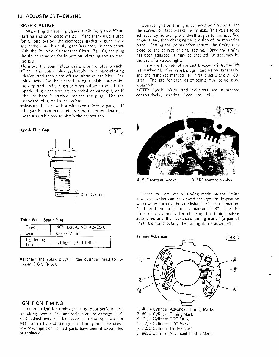
@Measure the gap with a wire-type thickness gauge. If
the gap is incorrect, carefully bend the outer electrode,
with a suitable tool to obtain the correct gap.
Spark Plug Gap
m
Table B1 Spark Plug
I Type I NGK D ~ E A . ND ~ 2 m
@Tighten the spark plugs in the cylinder head to 1.4
kg-m (1 0.0 ft-lbs).
Tightening
Toraue
IGNITION TIMING
Incorrect ignition timing can cause poor performance,
knocking, overheating, and serious engine damage. Peri-
odic adjustment will be necessary to compensate for
wear of parts, and the ignition timing must be check
whenever ignition related parts have been disassembled
or replaced.
1.4 kg-m (1 0.0 ft-lbs)
the correct contact breaker point gaps (this can also be
achieved by adjusting the dwell angles to the specified
amount) and then changing the position of the mounting
plate. Setting the points often returns the timing very
close to the correct original setting. Once the timing
has been adjusted, it may be checked for accuracy by
the use of a strobe light.
There are two sets of contact breaker points, the left
set marked "L" fires spark plugs 1 and 4 simultaneously,
and the right set marked "R" fires plugs 2 and 3 180'
later. The gap for each set of points must be adjusted
separately.
NOTE: Spark plugs and cylinders are numbered
consecutively, starting from the left.
A. "L" contact breaker B. "R" contact breaker
There are two sets of timing marks on the timing
advancer, which can be viewed through the inspection
window by turning the crankshaft. One set is marked
"1 4" and the other one is marked "2 3". The "F"
mark of each set is for checking the timing before
advancing, and the "advanced timing marks" (a pair of
lines) are for checking the timing it has advanced.
Timing Advancer
R
m
1. #1, 4 Cylinder Advanced Timing Marks
2. #1, 4 Cylinder Timing Mark
3. #I, 4 Cylinder TDC Mark
4. #2, 3 Cylinder TDC Mark
5. #2, 3 Cylinder Timing Mark
6. #2, 3 Cylinder Advanced Timing Marks
You're Reading a Preview
What's Included?
Fast Download Speeds
Online & Offline Access
Access PDF Contents & Bookmarks
Full Search Facility
Print one or all pages of your manual
$28.99
$37.99
Viewed 14 Times Today


Secure transaction
What's Included?
Fast Download Speeds
Online & Offline Access
Access PDF Contents & Bookmarks
Full Search Facility
Print one or all pages of your manual
$28.99
$37.99
Looking for a complete service workshop manual for KAWASAKI GPZ 400 - 500 - 550? This manual is designed for easy readability and contains highly detailed exploded pictures, diagrams, and step-by-step instructions. It covers Scheduled Maintenance, Engine, Chassis, Electrical, Supplement 1984 Model, and Supplement 1985 Model. Whether you're a professional mechanic or a DIY enthusiast, this manual will help you understand your motorcycle better. All pages are printable, making it a cost-effective solution to keep your motorcycle running smoothly for the long term.
How to obtain it? Simply click the purchase button to instantly download the manual. This saves you money and eliminates the need to pay extra costs and wait for delivery.


